

Page 1

FORM NO. 92-3889
Model No. 41185-90001 & UP
& PARTS MANUAL
ROPS
OPERATOR'S, SET-UP,
for the MULTI-PRO® 1100 Vehicle
To assure maximum safety, optimum
performance, and to gain knowledge of the
product, it is essential that you or any other
operator of this Vehicle read and understand
the contents of this manual before the engine
is ever started. Pay particular attention to the
SAFETY INSTRUCTIONS highlighted by the
triangular safety alert symbol.
The safety alert symbol means CAUTION,
WARNING or DANGER - personal safety
instruction. Failure to comply with the
instruction may result in personal injury.
SAFETY INSTRUCTIONS
Keep this Operator’s Manual in the plastic tube behind the operator seat.
It is very important that all persons operating this equipment have easy access to these instructions at
all times!
Carefully read and follow the “Set-Up” Instructions that are provided with this equipment and the Safety
Instructions in the Multi-Pro
RECOGNIZE SAFETY INFORMATION
TM
1100 Operator’s Manual.
This safety-alert symbol is used to call
attention to a dangerous situation, which
could result in serious injury or death to
the operator or a bystander.
Safety, mechanical and some general
information in this manual are emphasized.
DANGER, WARNING and CAUTION identify
safety messages. Whenever the triangular safety
symbol appears, it is followed by a safety
message that must be read and understood. For
more details concerning safety, read the Safety
Instructions on this page and page 2.
IMPORTANT identifies special mechanical
information and NOTE identifies general
information worthy of special attention.
These instructions are provided as a guide for the
safe operation and maintenance of this
equipment. However, the operator’s personal
safety, as well as those persons in the work area,
will depend on the careful actions and good
judgement of the operator. To reduce the
potential for injury or death, comply with the
following safety instructions.
BEFORE OPERATING:
1. Operate this machine equipped with this
ROPS only after reading and understanding the
contents of this manual and the Multi-Pro™
Operators Manual. A replacement manual is
available by sending complete model and serial
number to: Hahn Inc., 1625 N. Garvin,
Evansville, IN 47711.
1100
2. Keep all safety devices and decals in place. If
a safety device or decal is malfunctioning, illegible
or damaged, replace it before operating the
machine.
3. It is mandatory to wear the seat belt at all times
when operating the machine equipped with the
ROPS system. (Always adjust and secure Seat
Belt before operating the machine.)
WHILE OPERATING:
1. Since this attachment adds extra weight to the
vehicle, drive safely and cautiously to prevent loss
of control and possible upset.
2. Gross vehicle weight has a major impact on
your ability to stop and/or turn. Heavier loads and
heavier attachments make a vehicle harder to stop
or turn. The heavier the load, the longer it takes to
stop.
3. The ROPS is equipped with a roll bar, shoulder
restraints and seat belt. The ROPS system used
on the vehicle will reduce the risk of serious or fatal
injury in the unlikely event of a tip over, although
the system cannot protect the operator from all
possible injuries.
4. Replace a damaged ROPS, do not repair or
revise. Any alteration of ROPS must be approved
by the manufacturer.
©The TORO Company - 1999
All Rights Reserved
1
Page 2

SAFETY INSTRUCTIONS
SEAT BELT OPERATION:
1. Pull the seat belt across lap and latch. Extend
belt completely from retractor and adjust out
slack.
WARNING
Non-locking retractor effective only
when belt is fully extended.
• An improperly latched seat belt
could result in the operator being
thrown from the vehicle.
• Being thrown from vehicle can
result in serious injury or death.
• Read and understand these
instructions and charts, and all seat
belt safety information presented here.
TORQUE SPECIFICATION CHART
BOLT SIZE
3/8"
7/16"
1/2"
3. To be sure of optimum performance and
safety, always purchase genuine TORO
replacement parts and accessories. Replacement
parts and accessories made by other
manufacturers could be dangerous. Altering this
equipment in any manner may affect the
machine’s operation, performance, durability or
its use may result in injury or death. Such use
could void the product warranty of The TORO
Company.
TORQUE VALUE
30 FT. LB.
50 FT. LB.
75 FT LB.
MAINTENANCE:
1. Before servicing or making any adjustments
to the Sprayer:
A. Stop the Vehicle and set the parking brake.
B. Shut off the vehicle’s engine and remove
key from ignition.
C. Disengage all power and wait until all
moving parts have stopped.
2. Keep all nuts, bolts and other fasteners
tightened to torque. Replace any shields
removed during servicing or adjustments.
2
Page 3
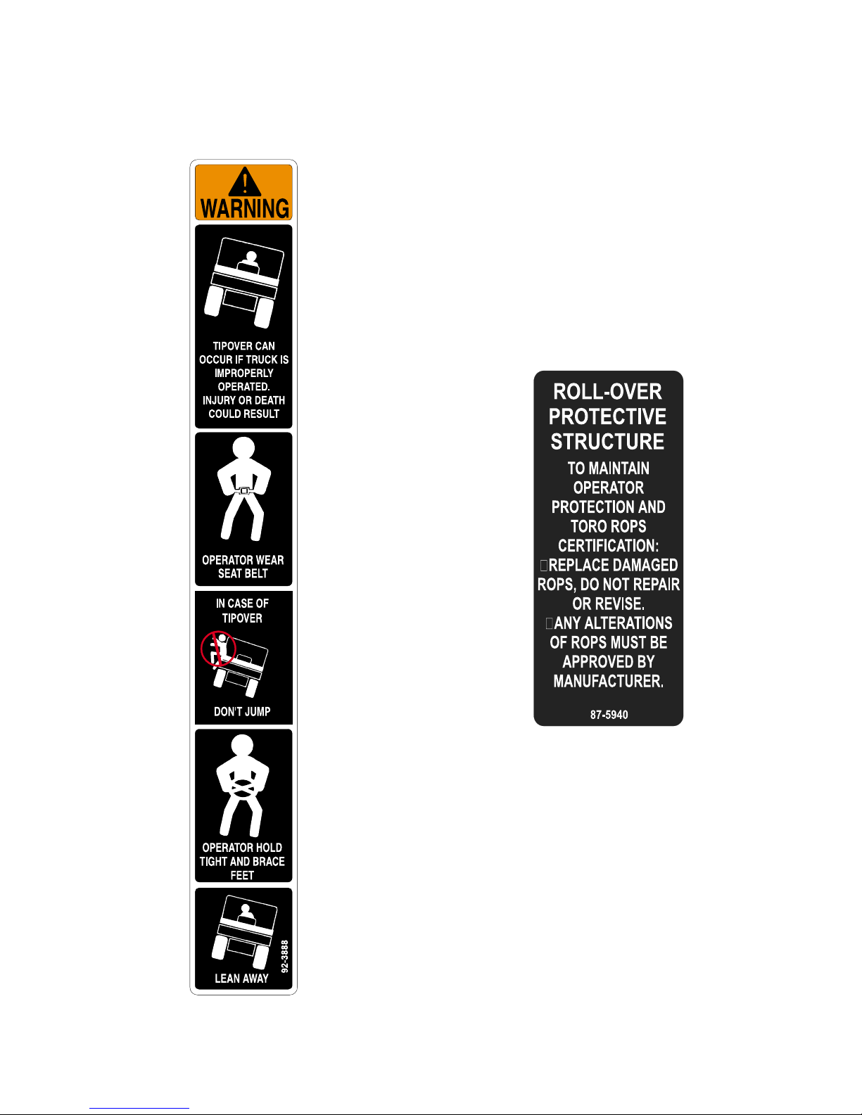
SAFETY AND INSTRUCTION DECALS
The following safety and instruction decals are installed on the Rops. If any become damaged or
illegible, replace them. Decals and part numbers are listed below and in the parts catalog. Order
replacements from your Authorized Toro Distributor.
Part No. 92-3888: Located on the
front of Rear ROPS Bar - R.H.S.
Part No. 87-5940: Located
below Decal No. 92-3888.
3
Page 4

SET-UP INSTRUCTIONS
IF INSTALLING OPERATOR ENCLOSURE AT
THIS TIME, DELETE STEPS 6-8, AND REFER
TO THE SET-UP INSTRUCTIONS PROVIDED
WITH THAT KIT FOR THESE ASSEMBLY
PROCEDURES.
IF MACHINE IS ALREADY EQUIPPED WITH A
HOSE REEL KIT, REMOVE AND DISCARD
EXISTING HOSE REEL MOUNT ANGLE
ASSEMBLIES.
AN ASSISTANT MAY BE NEEDED WHILE
INSTALLING THE ROPS PACKAGE ON THE
TORO MULTI-PRO™ 1100 AS OUTLINED IN THE
FOLLOWING STEPS.
Refer to illustrated parts list for the details of parts
used in assembling the ROPS.
NOTE: "RIGHT", "LEFT", "FRONT" AND "REAR"
ARE REFERENCED WHILE SEATED IN THE
OPERATORS POSITION.
1544
FIG. 1
1. Rear ROPS Bar 2. Vehicle Frame
2. Loosely mount the left hand ROPS bar to the
rear ROPS bar by screwing (2) 3/8" x 1" hex hd.
cap screws with lockwashers, into the insert
anchors located in the top of rear ROPS bar.
1543
1. Open shipping carton, remove the shipping
clamps and rear ROPS bar. Mount the ROPS
bar to the vehicle frame by inserting (8) 1/2" x 11/4" hex. hd. cap screws through the ROPS bar
and the vehicle frame. Start nuts on bolts by
hand. Use a torque wrench and torque nuts to
75 ft. lb. See FIG. 1.
4
1545
FIG. 2
1. R.H.-ROPS Bar 3. ROPS Cross Bar
2. L.H.-ROPS Bar 4. Rear ROPS Bar
3. Loosely mount the lower end of the hand
ROPS bar to the front vehicle frame using (2)
1/2" x 1-1/4" hex hd. cap screws, flatwashers, and
lock nuts. Start nuts on bolts by hand. See
FIG. 3.
Page 5

SET-UP INSTRUCTIONS
1546
FIG. 3
1. L.H.-ROPS Bar 2. Left Front Vehicle Frame
4. Loosely mount the right hand ROPS bar to
the rear ROPS bar by screwing (2) 3/8" x 1" hex
hd. cap screws with lockwashers, into the insert
anchors located in the top of the rear ROPS bar.
5. Loosely mount the lower end of the right
ROPS bar to the right front vehicle frame using
(2) 1/2" x 1-1/4" hex hd. cap screws, flatwashers,
and lock nuts. Start nuts on bolts by hand. See
FIG. 3.
6. Loosely mount the ROPS cross bar to the
right and left hand ROPS bars by screwing (4)
3/8" x 1" hex. hd. cap screw with flatwashers and
lockwashers, into the insert anchors located in
the ROPS bars. See FIG. 2.
7. Align the ROPS bars and using a torque
wrench, tighten the mounting bolts to their proper
torque specifications as outlined in the TORQUE
SPECIFICATION CHART.
1547
FIG. 4
1. Seat Belt Assembly 2. Rear ROPS Bar
1548
FIG. 5
1. Hose Reel Mounting Plate 2. Rear ROPS Bar
TORQUE SPECIFICATION CHART
BOLT SIZE
3/8"
TORQUE VALUE
30 FT. LB.
8. Mount the seat belt assembly to the rear ROPS
bar at a 45° angle using (2) 7/16" x 1-1/4" hex. hd.
cap screws, lockwashers, and hex nuts as shown
in FIG. 4. Using a torque wrench, torque nuts to
50 ft. lb.
NOTE: THE FOLLOWING STEP APPLIES ONLY
IF A HOSE REEL KIT IS TO BE INSTALLED ON
THE MULTI-PRO™ VEHICLE.
9. Mount the hose reel mounting plates to the
rear ROPS bar by screwing (4) 3/8" x 1" hex. hd.
cap screws with lockwashers attached, into the
insert anchors in the ROPS bar and tighten to 30
ft. lb. See FIG. 5.
7/16"
1/2"
50 FT. LB.
75 FT LB.
NOTE: TO ENSURE THE STRUCTURAL
RIGIDITY OF ROPS SYSTEM, MAINTAIN THE
TORQUE VALUES ON THE ATTACHING
HARDWARE AS OUTLINED ABOVE.
5
Page 6

1549
Ref.
10
11
12
13
14
15
16
1
2
3
4
5
6
7
8
9
Part No.
92-3793
92-3983
92-3964
323-6
3253-11
21-4191
324-5
325-5
3256-6
3256-4
32153-5
3217-8
3253-6
92-3801
92-3795
92-3799
ROPS
Description
Rear ROPS Bar
Insert Anchor 1/4" (with setting tool) f/w 92-3793
Hose Reel Mounting Plate
HHCS 3/8-16 UNC x 1"
Lockwasher 3/8
Seat Belt Assembly
HHCS 7/16-14 x 1-1/4"
HHCS 1/2-13 UNC x 1-14"
Flatwasher 1/2
Flatwasher 3/8
Lock Nut 1/2 UNC
Hex Nut 7/16 UNC
Lockwasher 7/16
ROPS Cross Bar
Right Hand ROPS Bar
Left Hand ROPS Bar
Qty.
1
23
2
12
8
1
2
12
4
4
12
2
2
1
1
1
6
Page 7

®
7
Page 8

®
8
 Loading...