

Page 1

FormNo.3429-703RevA
MMX-650E-SandMMX-850E-S
MortarMixers
ModelNo.60212—SerialNo.404320000andUp
ModelNo.60218—SerialNo.404320000andUp
ModelNo.60219—SerialNo.404320000andUp
Registeratwww.T oro.com.
OriginalInstructions(EN)
*3429-703*A
Page 2

WARNING
CALIFORNIA
Proposition65Warning
Thepowercordonthisproductcontains
lead,achemicalknowntotheState
ofCaliforniatocausebirthdefects
orotherreproductiveharm.Wash
handsafterhandling.
Useofthisproductmaycauseexposure
tochemicalsknowntotheStateof
Californiatocausecancer,birthdefects,
orotherreproductiveharm.
Introduction
Thismachineisdesignedtomixmortar,plaster,
reproongmaterial,grout,andothersmall-grained
cementproducts.Avehicleequippedwithan
appropriatepintlehitchorballhitchcantowthe
machine..
Readthisinformationcarefullytolearnhowtooperate
andmaintainyourproductproperlyandtoavoid
injuryandproductdamage.Youareresponsiblefor
operatingtheproductproperlyandsafely .
YoumaycontactTorodirectlyatwww.Toro.com
forproductsafetyandoperationtrainingmaterials,
accessoryinformation,helpndingadealer,orto
registeryourproduct.
Wheneveryouneedservice,genuineToroparts,or
additionalinformation,contactanAuthorizedService
DealerorToroCustomerServiceandhavethemodel
andserialnumbersofyourproductready .Writethe
numbersinthespaceprovided.
g028582
Figure1
1.Modelandserialnumberlocation
ModelNo.
SerialNo.
Thismanualidentiespotentialhazardsandhas
safetymessagesidentiedbythesafetyalertsymbol
(Figure2),whichsignalsahazardthatmaycause
seriousinjuryordeathifyoudonotfollowthe
recommendedprecautions.
g000502
Figure2
1.Safetyalertsymbol
©2018—TheToro®Company
8111LyndaleAvenueSouth
Bloomington,MN55420
Thismanualuses2wordstohighlightinformation.
Importantcallsattentiontospecialmechanical
informationandNoteemphasizesgeneralinformation
worthyofspecialattention.
TheDOTtireinformationislocatedonthesideof
eachtire.Thisinformationgivesloadandspeed
ratings.Replacementtiresshouldhavethesameor
betterratings.
Note:Thevariousmachinesinthismanualhave
differentweights;refertoSpecications(page12)to
ensurethatthetiresonyourmachinemeetorexceed
theweightrequirementsofyourmachine.
Contactusatwww.Toro.com.
2
PrintedintheUSA
AllRightsReserved
Page 3

Contents
Safety
Safety.......................................................................3
SafeOperatingPractices....................................3
SafetyandInstructionalDecals..........................7
Setup........................................................................8
1InstallingtheDumpHandle..............................8
2InstallingtheT owPole.....................................8
3InstallingtheSafetyChain...............................9
4AdjustingtheMixingPaddles.........................10
ProductOverview...................................................10
Controls............................................................11
Specications..................................................12
Operation................................................................14
PreparingtoT owtheMachine...........................14
ExtendingtheAxle............................................17
TowingtheMachine..........................................18
PreparingtoUsetheMachine...........................18
OpeningandClosingtheCowl..........................19
PoweringtheMachine......................................20
StartingandStoppingtheMotor........................21
ControllingthePaddles.....................................21
MixingtheMaterial...........................................22
UsingtheDrum.................................................24
Maintenance...........................................................25
RecommendedMaintenanceSchedule(s)...........25
Pre-MaintenanceProcedures..............................25
PreparingtheMachineforMaintenance............25
RemovingandInstallingtheDivider
Plate..............................................................25
Lubrication..........................................................26
LubricatingtheBearingsandSeals...................26
LubricatingtheMotorBearings.........................27
LubricatingtheDriveChain...............................28
BeltMaintenance................................................28
ServicingtheBelts............................................28
ReplacingtheBelts...........................................29
AligningthePulleys..........................................31
DriveChainMaintenance.....................................32
CheckingandAdjustingtheDrive
Chain............................................................32
PaddleMaintenance............................................33
AdjustingthePaddles.......................................33
Cleaning..............................................................35
CleaningtheMachine.......................................35
Storage...................................................................35
StoringtheMachine..........................................35
Troubleshooting......................................................36
Schematics.............................................................37
Improperlyusingormaintainingthemachinecan
resultininjury.Toreducethepotentialforinjury ,
complywiththesesafetyinstructionsandalways
payattentiontothesafetyalertsymbol
means:Caution,Warning,orDanger—personal
safetyinstruction.Failuretocomplywiththe
instructionmayresultinpersonalinjuryordeath.
,which
SafeOperatingPractices
Thisproductiscapableofamputatinghands.Always
followallsafetyinstructionstoavoidseriousinjuryor
death.
WARNING
Machiningorhandlingstone,masonry,
concrete,metal,andothermaterialscan
generatedust,mists,andfumescontaining
chemicals,suchassilica,knowntocause
seriousorfatalinjuryorillness,suchas
respiratorydisease,silicosis,cancer,birth
defects,orotherreproductiveharm.
•Controldust,mist,andfumesatthesource
wherepossible.Watershouldbeusedfor
dustsuppressionwhenfeasible.
•Usegoodworkpracticesandfollowthe
recommendationsofthemanufactureror
suppliers,OSHA,andotheroccupational
andtradeassociations.
•Alwaysfollowrespiratoryprecautions.
•Whenthehazardsfrominhalationcannot
beeliminated,theoperatorandany
bystandersshouldweararespirator
approvedbyOSHAforthematerialbeing
handled.
Training
•ReadtheOperator'sManualandothertraining
material.Iftheoperator(s)ormechanic(s)cannot
readorunderstandtheinformation,itisthe
owner'sresponsibilitytoexplainthismaterialto
them.
•Becomefamiliarwiththesafeoperationofthe
equipment,operatorcontrols,andsafetysigns.
•Alloperatorsandmechanicsshouldbetrained.
Theownerisresponsiblefortrainingtheusers.
3
Page 4

•Neverletchildrenoruntrainedpeopleoperateor
servicetheequipment.Localregulationsmay
restricttheageoftheoperator.
•Theowner/usercanpreventandisresponsible
foraccidentsorinjuriestopeopleordamageto
property.
Towing
Checkwithyourlocalcountyorstatetowingsafety
regulationsbeforetowingthemachine.
•Inordertoreducethepossibilityofanaccident
whiletransportingthemachineonpublicroads,
makesurethetowingvehicleismechanically
soundandingoodoperatingcondition.
•Turnoffthemotorbeforetransportingthemachine.
•Whentowingwithaballhitch,ensurethattheball
hitchyouareusingisthepropersizeforthehitch
coupleronthemachine.
•Whentowingwithapintlehitch,ensurethatthe
eyeofthetowpoleisthecorrectdimensionfor
thepintlehook.
•Inspectthehitchandcouplingforwear.Nevertow
themachinewithdamagedordefectivehitches,
couplings,chains,orothercomponents.
•Checkthetireairpressureonthetowingvehicle
andthemachine.
•Checkthetiretreadandsidewallfordamageand
wear.
•Properlyattachthesafetychainstothetowing
vehicle.
•Ensurethatthedirectionalandbrakelightsare
workingproperly(ifthemachineisequippedwith
thelightkit).
•Ensurethatthedirectional,backup,andbrake
lightsofthetowvehicleareworkingproperly.
•Beforetowing,checktomakecertainyour
machineiscorrectlyandsecurelyattachedtothe
towingvehicle.
•Ensurethatthesafetychainsareproperlysecured
tothevehicle,andleaveenoughslackforturning.
•Donotcarryanymaterialinthemachinewhen
towing.
•Avoidsuddenstopsandstarts.Thiscancause
skidding,orjackkning.Smooth,gradualstarts
andstopswillimprovetowing.
•Avoidsharpturnstopreventrolling.T owonlywith
avehiclethathasahitchdesignedfortowing.Do
notattachtowedequipmentexceptatthehitch
point.
•Donottowthemachinefasterthan88km/h(55
mph).
•Usecautionwhenbackingup;useaspotter
outsidethevehicletoguideyou.
•Donotallowanyonetositorrideonthemachine.
Preparation
Becomefamiliarwiththesafeoperationofthe
equipment,operatorcontrols,andsafetysigns.
4
Page 5

•Useonlyaccessoriesandattachmentsapproved
bythemanufacturer.
•Wearpersonalprotectiveequipmentand
appropriateclothingincluding:
–Hardhat
–Respiratorordustmask
–Faceshield
–Safetyglasses
–Hearingprotection
–Safetyshoes
–Longpants
–Shirtwithlongsleevesthataretightatthe
wrists
–Tight-ttinggloveswithoutdrawstringsorloose
cuffs
•Securelonghair,looseclothing,orjewelrythat
maygettangledinmovingparts.
•Operatingtheequipmentsafelyrequiresthefull
attentionoftheoperator.Donotwearradioor
musicheadphoneswhileoperatingthemachine.
•Ensurethatthemachineisonalevelsurface
beforeoperatingthemachine.
•Chockthetiresofthemachinetoprevent
unintendedmovement.
•Beforeeveryuse:
–Inspectthecoupler,ball,andhitch.
–Ensurethatalllightsarefunctioningproperly(if
themachineisequippedwithalightkit).
–Ensurethatthetiresareproperlyinatedas
recommended.
–Ensurethatthelugnutsaretightandtorqued
properly.
•Chockthetireswhenusingthemachine.
•Whennotusingthemachine,chockthetiresor
keepitattachedtothetowvehicle.
•Keephandsawayfromanymovingparts.Keep
feetawayfromthetiresandthefrontpost.
•Donotoperatethemachineoutdoorsintherain.
•Donotoperatethemachineundertheinuence
ofalcoholordrugs.
•Ensurethattheareaisclearofotherpeopleor
petsbeforeoperatingthemachine.Stopthe
machineifanyoneentersthearea.
•Neverplaceyourhandsoranysolidobjectintothe
drumwhenthemachineisinoperation.
•Donottouchpartswhichmaybehotfrom
operation.Allowthemtocoolbeforeattemptingto
maintain,adjust,orservicethemachine.
•Nevermovethemachinewhilethemotoris
running.
•Keepthecowlclosedandlatchedduringoperation.
•Ensurethatalltheguardsandshieldsaresecurely
inplacebeforeoperatingthemachine.
•EnsurethattheON/OFFswitchisintheOFF
positionbeforeconnectingthemachinetothe
electricalsource.
•Ifthemixingpaddlesstrikeaforeignobjectorif
themachineshouldstartmakinganunusualnoise
orvibration,stopthemotorandemptythedrum.
Waitforallmovingpartstocometoacomplete
stopandcool.Vibrationisgenerallyawarningof
trouble.Inspectforcloggingordamage.Clean
andrepairand/orreplacedamagedparts.
•Lightningcancausesevereinjuryordeath.Ifyou
seelightningorhearthunderinthearea,donot
operatethemachine;seekshelter.
–Ensurethatthemachineisproperlysecured.
Operation
•Neverrunthemachineinapoorlyventilated
orenclosedareawithoutproperrespiratory
protection.Dustfrommaterialsbeingmixedcan
beveryharmfultooperatorsandbystanders.
•Onlyoperatethemachineingoodlighting
conditions.
•Beforestartingthemachine,makesurethatthere
arenopersonsorobstaclesnearorunderthe
machine.
•Neverleavearunningmachineunattended.
Alwaysstopthemotorandverifythatallmoving
partshavestopped.
5
Page 6

MaintenanceandStorage
•Beforeperformingmaintenance,dothefollowing:
–Parkthemachineonlevelground.
–Stopthemotor.Waitforallmovementtostop
beforeadjusting,cleaning,orrepairing.
–Letthemotorcoolbeforeperforming
maintenanceorstoringthemachine.
–Unplugthemachinebeforemakinganyrepairs.
•Neverlubricate,service,repair,oradjustthe
machinewhileitisrunning.
•Keepequipmentmaterialsclearfromthemotor.
•Neverallowuntrainedpersonneltoservicethe
machine.
•Keephands,feet,andclothingawayfrommoving
parts.Ifpossible,donotmakeadjustmentswith
themotorrunning.
•Keepallpartsingoodworkingconditionandall
hardwaretightened.Replaceallwornordamaged
decals.
•Removeanybuildupofgrease,oil,ordebrisfrom
themachine.
•Donotmodifytheelectricalconnectorsorwiring.
•Donotconnectthegroundcircuitofthemachine
totheenergizedcircuitoftheelectricalsource.
•Donottamperwithsafetydevices.
•Chockthetireswhenstoringthemachine.
•Keepallnuts,bolts,screws,andhoseclamps
securelytightened.Keepequipmentingood
condition.
•Toensureoptimumperformanceandcontinued
safetycerticationofthemachine,useonly
genuineT ororeplacementpartsandaccessories.
Replacementpartsandaccessoriesmadeby
othermanufacturerscouldbedangerous,and
suchusecouldvoidtheproductwarranty..
6
Page 7
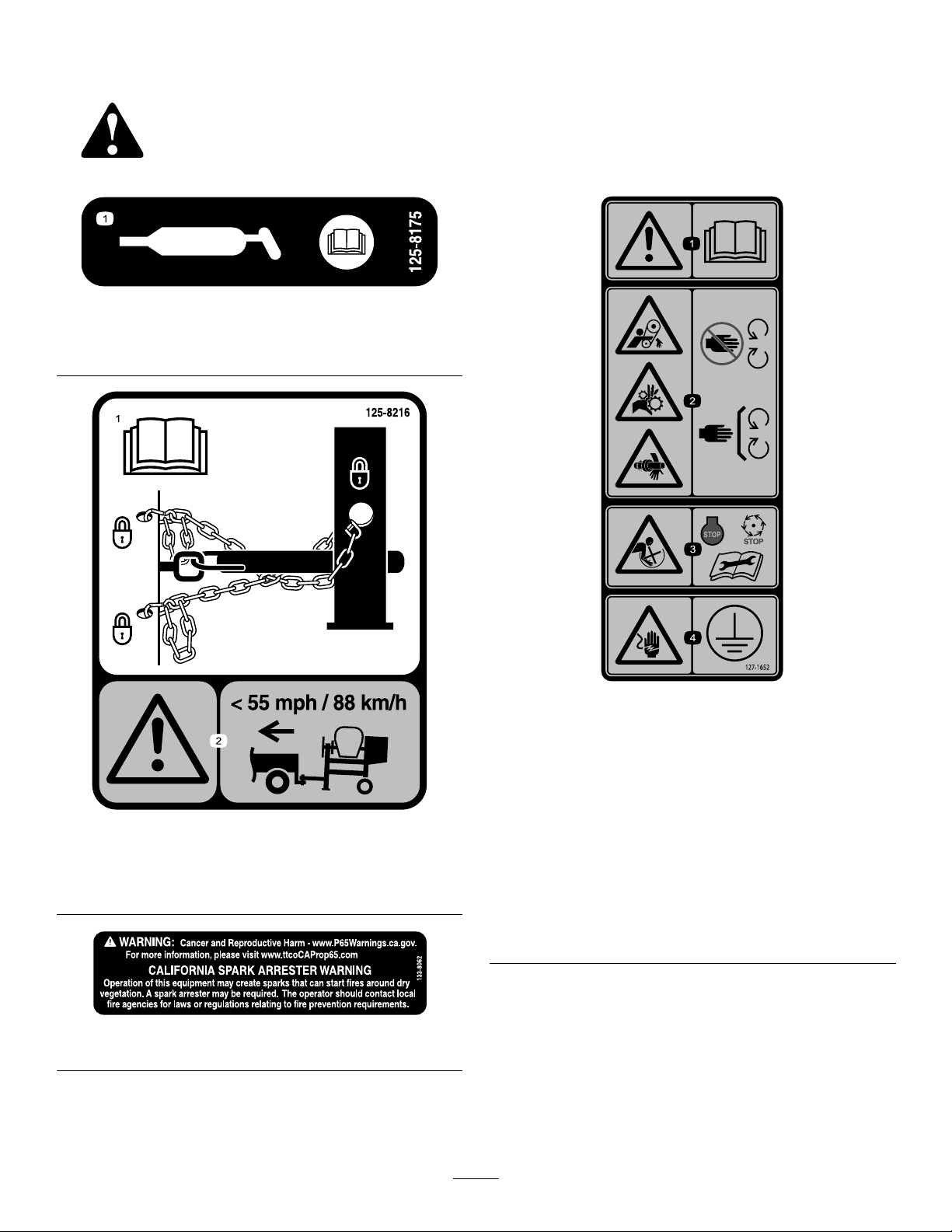
SafetyandInstructionalDecals
Safetydecalsandinstructionsareeasilyvisibletotheoperatorandarelocatednearanyarea
ofpotentialdanger.Replaceanydecalthatisdamagedorlost.
125–8175
1.ReadtheOperator’sManualforinformationongreasing
themachine.
decal125-8175
1.ReadtheOperator’s
Manualforinformationon
howtotowthemachine.
125–8216
133-8062
2.Warning—limittowing
speedtolessthan55mph
/88km/h.
decal127-1652
127–1652
1.Warning—readthe
Operator’sManual.
decal125-8216
decal133-8062
2.Handandarm
entanglementatthe
beltdrive;crushinghazard
ofhand;entanglement
hazardofhandatthe
shaft—keephandsaway
frommovingparts;keep
allguardsandsafetiesin
place.
3.Entanglementhazardat
paddles—stopthemotor
andwaitforallmoving
partstostopbefore
servicingthemachine.
4.Shockhazard—makesure
themachineisgrounded
beforeoperation.
7
Page 8
Setup
LooseParts
Usethechartbelowtoverifythatallpartshavebeenshipped.
ProcedureDescription
Dumphandle1
1
2
3
4
Bolt2
Nut2
Towpolekit(soldseparately)
Safetychain(soldwithoptionaltowpole
kit)
Connectinglink(soldwithoptionaltow
polekit)
Nopartsrequired
1
InstallingtheDumpHandle
Partsneededforthisprocedure:
1Dumphandle
2Bolt
2Nut
Qty.
Installthedumphandle.
1Installthetowpole.
1
Installthesafetychain.
2
–
Adjustingthemixingpaddles.
Use
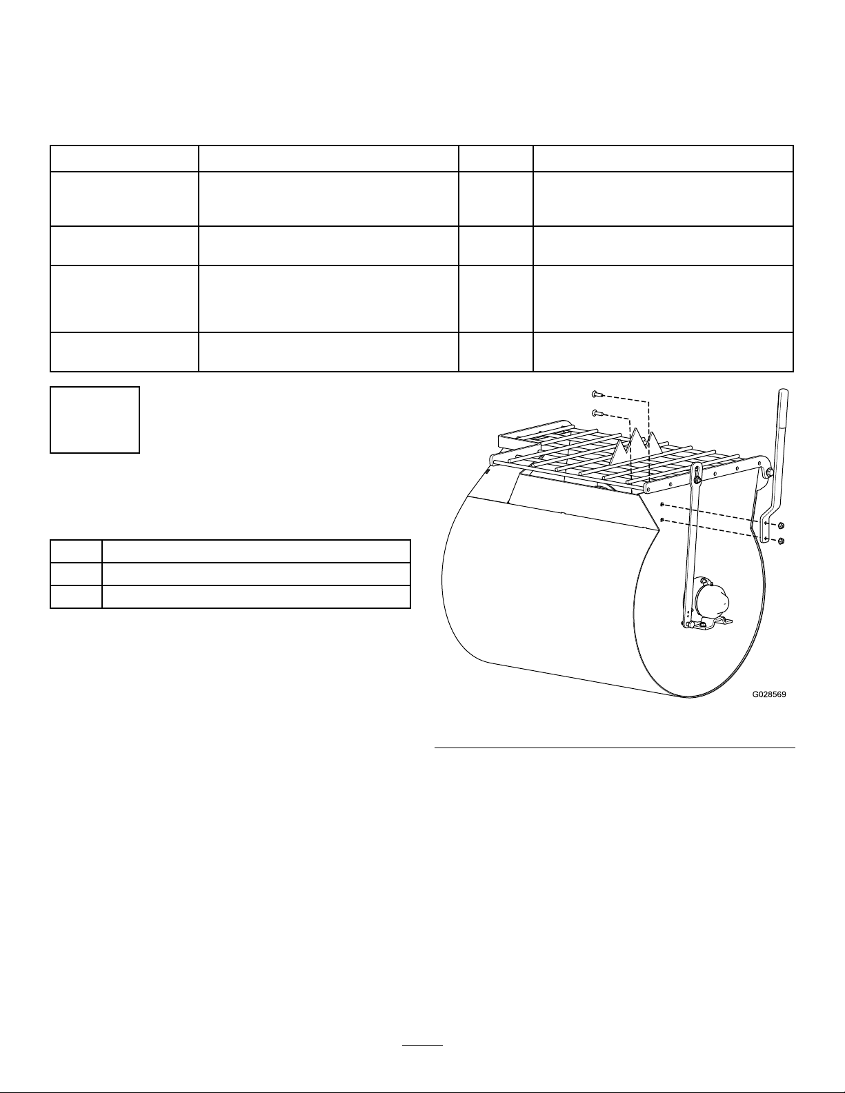
InstallingtheDumpHandletothe
Drum
1.Cutthecabletiestoremovethedumphandle
fromtheundersideofthegrate.
2.Positionthedumphandlesothattheboltholes
alignwiththeboltholesinthedrum(Figure3).
g028569
Figure3
3.Insert1carriageboltintothesquarebolthole
andslidethecorrespondingholeofthedrum
handleoverit(Figure3).
4.Installanutontothebolt,andtightenit.
5.Repeatthepreviousstepsfortheremaining
carriagebolt.
8
Page 9
2
3
InstallingtheTowPole
Partsneededforthisprocedure:
1
Towpolekit(soldseparately)
InstallingtheTowPoletothe
Machine
Note:Thetowpoleispurchasedseparatelyand
includesthenutandboltneededforinstallation.
Themachinehasthefollowingtowpoleoptions:
HitchTypeLength
50mm(2inch)ball—stamped78.7cm(31inches)
50mm(2inch)ball—forged78.7cm(31inches)
Pintle
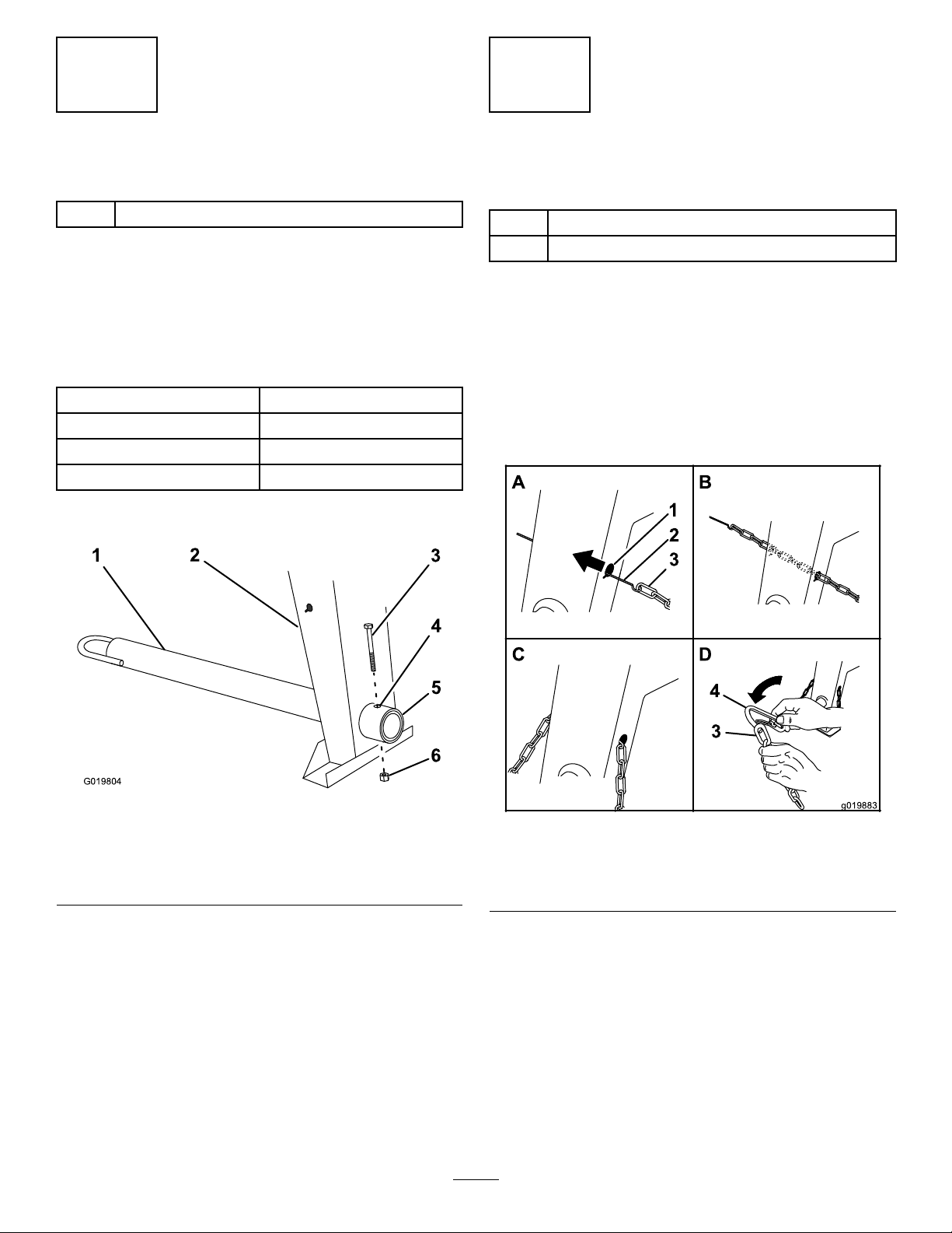
1.Removetheboltandnutfromthetowpole
(Figure4).
78.7cm(31inches)
InstallingtheSafetyChain
Partsneededforthisprocedure:
1
Safetychain(soldwithoptionaltowpolekit)
2
Connectinglink(soldwithoptionaltowpolekit)
InstallingtheSafetyChain
Note:Thesafetychainispartoftheoptionaltow
polekit.
1.Formahookontheendofabendablepiece
ofrodorstiffwire(notincluded),andinsertit
throughbothkeyholesinthefrontpostofthe
machine(Figure5A).
Figure4
1.Towpole4.Bolthole
2.Frontpost
3.Bolt6.Nut
2.Slidethetowpoleforwardandaligntheholein
thepolewiththeholeintheframetting(Figure
4).
3.Inserttheboltthroughtheholesinthettingand
thepole(Figure4).
4.Threadthenutontotheboltandtightenthem
untiltheyaretightagainsttheframetting
(Figure4).
5.Frametting
Note:Iftheself-lockingnyloninsertinthe
locknutwearswithuse,replacethenutwitha
newGrade5orGrade8locknut.
g019804
g019883
Figure5
1.Keyhole
2.Rodorwire(notincluded)4.Connectinglink
2.Attachthesafetychaintothelengthofrodor
wire(Figure5A).
3.Pulltherod,orwire,andthesafetychain
throughbothkeyholes(Figure5B).
3.Safetychain
Note:Ensurethatapproximatelyequallengths
ofsafetychainextendfromeithersideofthe
frontpost.
9
Page 10

InstallingtheConnectingLinks
Note:Theconnectinglinksarepartoftheoptional
towpolekit.
1.Aligntheconnectinglinktothelastlinkinone
endofthesafetychain(Figure5D).
2.Inserttheconnectinglinkthroughthechainlink
untiltheconnectinglinksnapsclosed.
3.Repeatsteps1and2toinstalltheother
connectinglinkintheotherendofthesafety
chain.
4
AdjustingtheMixing
Paddles
NoPartsRequired
Procedure
Ifthemixingpaddlesandwipersneedadjustment,
adjustthepaddlesandwipers;refertoAdjustingthe
Paddles(page33).
ProductOverview
Figure6
1.Rearcowl
2.Frontcowl8.Dumplatch14.Axle
3.Grate
4.Bagsplitter10.Towpole
5.Dumphandle
6.Grateliftarm
7.Clutchlever13.Chute
9.Frontpost15.Wheel
11.Safety-chain
keyhole
12.Drum
g028571
assembly
16.Cowllatch
10
Page 11

Controls
Becomefamiliarwithallthecontrolsbeforeyoustart
themotorandoperatethemachine.
ClutchLever
Theclutchleverisusedtoengageanddisengage
motorpowertothepaddles.
DumpHandle
Usethedumphandletorotatethedrumtothedump
positionandtorotatethedrumtothemixposition
(upright).
Figure7
1.Clutchlever
DrumLatch
Thedrumlatchsecuresthedrumtothemixposition
(upright)formixingoperationsandwhentransporting
themachine.
g019875
g028572
Figure9
1.Dumphandle
VoltageBlock
Usethevoltageblocktosettheoperatingvoltagefor
themachine(Figure10).
1.Drumlatch
g019877
Figure8
11
Page 12

1.Voltageblock
MotorON/OFFSwitch
TheON/OFFswitch(Figure12)allowstheoperatorof
themachinetostartandstopthemotor.Thisswitchis
locatedonthefrontofthemotor.Itismarked(ON)and
(OFF).RotatetheON/OFFswitchtotheONpositionto
startandrunthemotor.RotatetheON/OFFswitchto
theOFFpositiontostopthemotor.
g029823
Figure10
MotorControls
Thefollowingmotorcontrolsarefoundonallmodels:
Figure11
1.Thermal-overload
protectorresetbutton
2.ON/OFFswitch
3.Powercord
g020669
Figure12
1.MotorON/OFFswitch
g022280
Specications
Note:Specicationsanddesignaresubjecttochangewithoutnotice.
MachineSpecications
12
Page 13

MachineSpecications(cont'd.)
Model602126021860219
BatchCapacity0.17cubicm(6.0cubicft)0.23cubicm(8.0cubicft)0.23cubicm(8.0cubicft)
TotalVolume
Length
(withouttowpole)
Width
0.20cubicm(7.1cubicft)0.25cubicm(9.0cubicft)0.25cubicm(9.0cubicft)
150cm(59inches)168cm(66inches)168cm(66inches)
86cm(34inches)86cm(34inches)86cm(34inches)
Height
Weight
Axle
Motor1.5hpBaldorElectric1.5hpBaldorElectric2hpBaldorElectric
142cm(56inches)142cm(56inches)142cm(56inches)
250kg(550lb)275kg(605lb)275kg(605lb)
86to117cm(34to46inches)
extendable
86to117cm(34to46inches)
extendable
86to117cm(34to46inches)
extendable
13
Page 14

Operation
Important:Beforeoperating,removeanydebris
fromthemachine.Ensurethattheareaisclear
ofpeople.
PreparingtoTowthe
Machine
CheckingtheTiresandWheels
ServiceInterval:Beforeeachuseordaily—Inspect
thetiresandwheels.
WARNING
Failuretomaintaincorrecttirepressure
mayresultintirefailureandlossofcontrol,
resultinginpropertydamageandserious
injuryordeath.
Important:Ensurethatyourtowvehiclehas
towingcapacityfortheweightofthemachine.
Important:UseaClass2orlargerreceiver.
Note:Ensurethatyourtowvehiclehasthe
appropriatehitchtotowthemachine;optionsinclude
a50mm(2inch)ballhitchorapintlehitch.
Note:Ifthemachineisequippedwithatrailer-light
kit,ensurethattheelectricalconnectorofthetow
vehicleiscompatiblewiththeelectricalconnectorof
themachine.Themachineusesastandard4-at
plug.Ifyourtowvehiclehasadifferenttypeofplug,
obtainanadapterfromanautomotivepartsstore.
1.Stopthemotor,unplugthemachine,andempty
thedrum.
2.Ifthedrumhasaccumulatedanywater,dump
thedrum;refertoDumpingtheDrum(page24),
steps1,3,4,and5.
3.Usingthedumplever,positionthedrumsothat
itisinthemixposition(upright)andlocked.
4.Closethecowlandsecurethecowllatches
(Figure13).
•Checkthetirepressurefrequentlyto
ensureproperination.Ifthetiresarenot
inatedtothecorrectpressure,theywill
wearprematurely .
•Inspectthetireconditionbeforetowing
andafteranyoperatingaccident.
TheDOTtireinformationislocatedonthesideof
eachtire.Thisinformationgivesloadandspeed
ratings.Replacementtiresshouldhavethesame
orbetterratings.Formoreinformationgoto
http://www.nhtsa.gov/Vehicle+Safety/Tires.
Note:Thevariousmachinesinthismanualhave
differentweights;refertoSpecications(page12)to
ensurethatthetiresonyourmachinemeetorexceed
theweightrequirementsofyourmachine.
1.Visuallyinspectthetiresfordamageandwear
(Figure14andFigure15).
Figure13
5.Extendtheaxle;refertoExtendingtheAxle
(page17).
g020836
Figure14
1.Exampleoftirewearcausedbyunderination
g019741
g010293
Figure15
1.Exampleoftirewearcausedbyoverination
14
Page 15

2.Ensurethatthetiresareinatedtothecorrect
airpressure.ThefollowingTireAirPressure
tableshowstheappropriateairpressureforthe
tiresasinstalledatthefactory.
Important:Alwayschecktheinformationon
theactualtiresforthecorrectairpressure
requirement.
Important:Themostcommoncauseoftire
troubleisunder-ination.Maintainfullair
pressure.
TireAirPressure
ModelTirepressure
68012
68018,68019
Max414kPa(60psi)
Max241kPa(35psi)
3.Ensurethatthewheellugnutsaretorquedto
108to122N-m(80to90ft-lb).
Note:Checkthetorqueofthewheellugnuts
initiallyandaftertowing.
Note:T orquethelugnutsinthesequence
showninFigure16.
HitchingaMachinewithaStamped
BallCoupler
1.Applychassisgreasetothesocketofthe
couplerandtheareaoftheclampthatcontacts
theball.Oilthepivotpointsandslidingsurfaces
ofthecouplerwithSAE30motoroil.
2.Openthecouplerlatch(Figure17).
Figure16
g021107
g020359
Figure17
1.Bail
2.Safetypin
3.Positionthecouplerontopofthehitchball
(Figure17).
4.Closethecouplerlatch(Figure17).
5.Openthebailonthesafetypinandinsertthepin
throughtheholeinthelatch(Figure17).
6.Rotatethefreeendofthebailovertheendof
thesafetypinthatisprotrudingthroughthelatch
(Figure17).
15
Page 16

7.Ifthemachineisequippedwithatrailer-lightkit,
connectthewireplugofthetowvehicletothe
wireplugofthemachine.
6.Ifthemachineisequippedwithatrailer-lightkit,
connectthewireplugofthetowvehicletothe
wireplugofthemachine.
HitchingaMachinewithaForged
BallCoupler
1.Applyremovablethread-lockingcompoundto
thethreadsofthecouplerbolttopreventthe
couplerhandlefromcomingloose(Figure18).
Important:Applythread-lockingcompound
asneededinthefuture.
HitchingaMachinewithaPintle
HitchTowPole
1.Removethepinfromthepintlehitchandopen
it(Figure19).
Figure18
1.Couplerhandle
2.Coupler
3.Clamp
4.Bolt
5.Hitchball
2.Applychassisgreasetothesocketofthecoupler
andtheareaoftheclampthatcontactstheball.
3.Pushthecouplerboltupthroughthecoupler
clampandthecouplertop,andconnectthe
couplerhandletothebolt(Figure18).
4.Positionthecouplersothesocketisontopof
thehitchballandtheclampisundertheball.
5.Turnthecouplerhandleclockwisetothreadit
ontotheboltuntilitissecure(Figure18).
Note:Useawrenchtokeeptheboltfrom
spinning.
g019807
g019809
Figure19
2.Positiontheringonthetowpoleontothehook
ofthepintlehitch(Figure19).
3.Closethetopofthepintlehitchandsecureit
withthepin(Figure19).
4.Ifthemachineisequippedwithatrailer-lightkit,
connectthewireplugofthetowvehicletothe
wireplugofthemachine.
16
Page 17

ConnectingtheSafetyChainsto
theTowVehicle
Connectthesafetychaintothemachineandthetow
vehicleasfollows:
1.Pullthesafetychainthroughtheslotsinthe
keyholeslocatedinthefrontpostofthemachine,
sothatthereisjustenoughslackoneachside
forturningaroundcornerswhentowingthe
machine(Figure20).
Note:Stowtheexcesschaininsidethebottom
ofthefrontpostbypushingitintothekeyholes
andlatchingtheappropriatelinksintothe
keyholeslots.
2.Crossbothlengthsofchainunderthetowpole.
Note:Crossingthechainsdecreasesthe
chancesofthefrontofthemachinedropping
tothegroundifthehitchdoesnotholdthe
connection.
g021178
Figure21
1.Connectinglink3.Chainlink
2.Safetychainmounting
pointontowvehicle
ExtendingtheAxle
Figure20
1.Connectinglinks3.Chaincrossedundertow
pole
2.Keyholesinfrontpost
3.Connecteachlengthofchaintothesafety
chainmountingpointonthetowvehiclewiththe
connectinglinks(Figure21).
WARNING
Themachineisnotstablewhentowingitwith
theaxleinthenarrowposition.
Towthemachinewiththeaxleinthewide
position.
Important:Adjusttheaxletothenarrowposition
onlytomovethemachinethroughanarrow
accesspoint,suchasthegateofafenceorthe
g021177
doorwayofabuilding.
PreparingtoChangetheAxle
Width
1.Movethemachinetoaleveljob-sitesurface.
2.Disconnectthemachinefromthetowvehicle.
3.Chockthetires.
4.Ensurethatthedrumisemptyandinthemix
position(upright).
5.Ensurethatthedrumlatchisengagedand
thatthedrumdoesnotrotatetowardthedump
position.
17
Page 18

AdjustingtheAxleWidth
WARNING
Mechanicalorhydraulicjacksmayfailto
supportthemachineandcauseseriousinjury.
Usejackstandswhensupportingthe
machine.
1.Alignajackwithanadequateliftheight
andweightcapacityundertheaxle;referto
Specications(page12).
2.Liftthemachineuntilthetiresareofftheground.
5.Aligntheinneraxletothedesiredpositionas
follows:
•Slideeachsideoftheaxleinwardtothe
narrowposition(Figure23).
•Slideeachsideoftheaxleoutwardtothe
wide(tow)position(Figure23).
6.Aligntheholesoftheinneraxlewiththeholes
oftheouteraxle.
7.Inserttheboltsthroughtheaxleholes(Figure
23).
8.Threadthenutsontothebolts,andtorquethe
nutsto87N-m(64ft-lb).
3.Useajackstandateachsupportpointonthe
rearframeextension(Figure22).
Figure22
1.Supportpoint(2)
4.Removetheboltsandnutsthatsecuretheinner
axletotheouteraxle(Figure23).
TowingtheMachine
WARNING
Towingthemachineathighspeedincreases
theriskofahitchmalfunctionandtirefailure.
Higherspeedsalsoincreasethemomentum
ofthemachineandbrakingdistance.Ifthe
machinebecomesdetachedfromthetow
vehicleathighspeed,itcouldcausedamage
toproperty,orinjuryordeathtobystanders.
Donotexceed88km/h(55mph)whentowing
themachine.Forpoorroadconditionsor
inclementweather,reducespeedaccordingly.
WARNING
g029390
Towingthemachinewithmaterialinthedrum
increasestheriskofahitchmalfunctionand
tirefailure.Inaddition,materialcouldbounce
outofthedrumandhitothervehiclesand/or
people.Materialinthedrumincreasesthe
weight,whichaffectsmomentumandbraking
distance.
Figure23
1.Wideposition(towing)4.Nut(narrowposition)
2.Narrowposition
3.Nut(wideposition)6.Bolt(narrowposition)
5.Bolt(wideposition)
Donottowthemachinewithmaterialinthe
drum.
•ReviewandunderstandSafeOperatingPractices
(page3).
•Testthebrakesofthetowvehiclebeforetowing.
•Avoidsuddenstartsandstopswhiletowingthe
machine.
g020020
PreparingtoUsethe
Machine
•Reviewallofthesafetydecalsonthemachine.
•Useahard-hat,hearingprotection,ashirtwith
longsleevesthataretightatthewrists,tight-tting
18
Page 19

gloveswithoutdrawstringsorloosecuffs,eye
protection,andadustmaskorrespirator.A
meshvisoralonedoesnotprovidesufcienteye
protection;supplementwithprotectiveglasses.
OpeningandClosingthe
Cowl
•Ensurethatyouarefamiliarwiththesafety
regulationsandshutdownproceduresdescribedin
theOperator’sManual.
•Ensurethatallguardsareinplaceandingood
condition.
•Ensurethatthepaddlesareinplaceandingood
condition.
•Checkallthegreasettingstoensurethatthe
machineisproperlylubricated.
•Whenpreparingtomixmaterial:
1.Movethemachinetoaleveljob-sitesurface.
2.Removethemachinefromthetowvehicle.
3.Chockthefrontandbackofthetiresto
preventthemachinefrommoving.
4.Ensurethatthedrumisinthemixposition
(upright).
5.Ensurethatthedrumlatchisengagedand
thatthedrumdoesnotrotatetowardthe
dumpposition.
OpeningtheCowl
1.Atthesideofthemachinewherethefrontcowl
andrearcowlmeet,graspthelatchandpullitoff
fromthelatchanchorontherearcowl(Figure
24).
Figure24
1.Latch3.Receiver
2.Latchanchor
2.Repeatstep1ontheoppositesideofthe
machine.
3.Atthebackofthemachinewheretherearcowl
meetstheframeofthemachine,graspthelatch
andpullitofffromthelatchanchoronthecowl
(Figure24).
4.Rotatetherearcowlupandforwarduntilitis
fullypositionedontopofthefrontcowl(Figure
24).
4.V-tting
ClosingtheCowl
1.Rotatetherearcowlrearwardanddownuntil
thereceiveratthebottomcenterofthecowlis
alignedwiththeV-ttingandushontheframe
ofthemachine(Figure24).
g020906
19
Page 20

2.Atthebackofthemachine,graspthelatchand
pullitontothelatchanchorontherearcowl.
3.Atthesideofthemachine,graspthelatchand
pullitontothelatchanchorontherearcowl.
4.Repeatstep3attheoppositesideofthe
machine(Figure24).
PoweringtheMachine
SettingtheOperatingVoltage
Themachinecanoperatewitha115Vor230Vsupply
voltage.Thevoltageblockdeterminestheoperating
voltageofthemachine(Figure10).Usethefollowing
stepstochangetheoperatingvoltage:
1.Parkthemachineonlevelground.
2.Stopthemotorandunplugthemachine.
3.Removethe2screwssecuringthevoltageblock
tothemotor.
4.Removethevoltageblockfromthemotor,rotate
thevoltageblock180degreesandplugitback
intothemotor.
5.Securethevoltageplugtothemotorwiththe2
screwsthatyoupreviouslyremoved.
Toreducetheriskofelectricshock,thismachine
hasapolarizedplug(uniquebladeshapesand
widths).Useonlyapolarizedplugandsocketthatis
compliantwithNEMAspecicationsandanextension
cordthatisUL-listed(CSAcertiedinCanada)and
recommendedforoutdooruse.Apolarizedplugwillt
inapolarizedcordonly1way.Iftheplugdoesnott
fullyintothecord,turnthecord.Ifitstilldoesnott,
purchaseanappropriateextensioncord.Ifyouhavea
polarizedextensioncordandtheextensioncordplug
doesnottfullyintothewallreceptacle,turntheplug.
Ifitstilldoesnott,contactaqualiedelectricianto
installtheproperoutlet.Donotchangethemachine
plugorextension-cordpluginanyway.
Note:Themachineusesatwist-lockingplug.
ExtensionCords
Length
15.2m(50ft)10AWG
22.8m(75ft)10AWG
30.4m(100ft)8AWG
WireGauge
Note:Donotuseanextensioncordover30.4m
(100ft)long.
Note:Usetheinstructionsonthevoltageblockto
determinethevoltageblocksetting.
ConnectingtoaPowerSource
DANGER
Contactwithwaterwhileoperatingthe
productcouldcauseelectricshock,causing
injuryordeath.
•Donothandletheplugorthemachinewith
wethandsorwhilestandinginwater.
•Useonlyanextensioncordrecommended
foroutdoorcold-weatheruse.
Important:Checktheextensioncordfrequently
duringuseforholesorcracksintheinsulation.
Donotuseadamagedcord.Donotrunthecord
throughstandingwaterorwetgrass.
Important:Useonlyextensioncordswith
terminalsandsocketsforthelive,neutral,and
groundwires.
Important:Connectthemachinetoonly
areceptaclewithlive,neutral,andground
connections.
Important:Theconnectingwiresorextension
cordshouldbeasshortaspossibleandin1piece.
20
Page 21

PoweringtheMachinewitha
PortableGenerator
Whenusingaportablegeneratorasanelectrical
source,ensurethefollowingpoweroutput
specications:
Important:Ensurethatthepaddlesspin
freely.Checkforstone,masonry ,orconcrete
materialbetweenthepaddlesandthedrum.
4.Onthesideofthejunctionboxforthemotor,
presstheresetbuttonforthethermal-overload
protector(Figure25).
ModelVoltageAmperesKilowatt
68012
68018
68019
115V/
230V
115V/
230V
115V/
230V
19A/
9.5A
19A/
9.5A
24A/
12A
hour
2.2to2.3
Kw
2.2to2.3
Kw
2.2to2.3
Kw
ResettingtheMotor
Theelectricalmotorforthemachineisequippedwith
adeviceforthermal-overloadprotection.Intheevent
thatthemotorshutsdownautomatically,resetthe
thermal-overloadprotectorasfollows:
1.MovetheON/OFFswitchtotheOFFposition;
refertoFigure12.
2.Disconnecttheelectricalplugforthemachine
fromthepowersource(Figure25).
Frequency/
phase
60Hz/
single
60Hz/
single
60Hz/
single
5.Connecttheelectricalplugforthemachineto
thepowersource.
6.RotatetheON/OFFswitchtotheONpositionand
ensurethatthemotorstartsnormally .
7.RotatetheON/OFFswitchtotheOFFposition.
StartingandStoppingthe
Motor
StartingtheMotor
1.Plugthepowercordintoaproperelectrical
outlet.
2.SwitchtheON/OFFswitchtotheONposition.
3.MovetheclutchlevertotheONposition;referto
ControllingthePaddles(page21)
StoppingtheMotor
WARNING
Figure25
1.Thermal-overload
protectorresetbutton
2.ON/OFFswitch
3.Electricalplug
3.Allowtheelectricmotorofthemachinetocool
untilitiswarmtothetouchorcooler.
Inanemergencysituation,stopthemotor
immediately.
1.MovetheclutchlevertotheOFFposition;refer
toControllingthePaddles(page21).
2.SwitchtheON/OFFswitchtotheOFFposition;
refertoMotorON/OFFSwitch(page12).
3.Unplugthepowercord.
ControllingthePaddles
DANGER
Thismachineiscapableofamputatinghands.
g020654
•Stayintheoperator’spositionwhilethe
machineisrunning.
•Keepallbystandersasafedistancefrom
themachine.
•Stopthemachineimmediatelyifany
peopleoranimalsentertheworkarea.
•Neverplaceanypartofyourbodyintoa
positionthatcausesanunsafeoperating
condition.
21
Page 22

Important:Ensurethatthepaddlesdonotturn
whentheclutchleverisintheOFFposition.
Usetheclutchlevertocontrolthepowertransmission
tothepaddlesofthemachine.
UsingtheClutchLever
Movetheclutchleverclockwisetoengagetheclutch,
andcounterclockwisetodisengagetheclutch(Figure
26).
g019873
Figure26
1.OFFposition2.ONposition
MixingtheMaterial
DANGER
Eyeandskincontactwithconcretematerials
andbreathingthedustinvolvedishazardous
toyourhealth.
•Ensurethatthereisadequateair
ventilation.
•Wearadustmasktopreventinhalationof
dustwhileusingthemachine;refertoSafe
OperatingPractices(page3).
•Avoiddirectcontactofcementand
concretematerialswithskinandeyes.
DANGER
Contactwiththemixingpaddlescouldcause
damageorinjury.
Neverputyourhandsinsidethedrumatany
time.
Important:Donotaddmorematerialthan
thebatchcapacityofthemachine;referto
Specications(page12).
22
Page 23

Note:Followthemanufacturer’sinstructionsthatare
printedonthepackagingoftheproductyouareusing.
MixingaBatchofMaterialinthe
Machine
1.Ensurethatthereisnoold,loosematerialin
thedrumthatcancontaminatethebatchof
material;refertoCleaningtheDrum(page24)
andDumpingtheDrum(page24),thenreturn
thedrumtotheuprightposition.
Note:Ensurethatthedrumisinthemix
position(upright)andthedrumlatchisengaged.
2.MovetheclutchlevertotheOFFposition;refer
toControllingthePaddles(page21).
3.Startthemotor;refertoStartingtheMotor(page
21).
4.MovetheclutchlevertotheONposition;referto
ControllingthePaddles(page21).
5.Addtheingredientsforthebatchasfollows:
A.Pourwaterintothedrumthroughthegrating
ofthedrumguard.
B.Addtheplaster,cement,orotherbinding
material.
Note:Youcanopenbagsofcement,
plaster,andbindingmaterialsbylowering
thebagontothebagsplitter(Figure27).
Figure27
g021179
C.Ifyouareusingsandand/orother
reinforcingmaterials,addthemintothe
drum.
6.Allowthepaddlestomixthematerialuntilthe
ingredientshaveauniformappearance.
Note:Ifneeded,addwaterorplaster,cement,
orotherbindingmaterialuntiltheconsistency
ofthebatchiscorrect.
23
Page 24

7.Releasethedrumlatchanddumpthedrum;
refertoDumpingtheDrum(page24).
UsingtheDrum
DANGER
Contactwiththemixingpaddlescouldcause
damageorinjury.
Neverputyourhandsinsidethedrumatany
time.
3.Liftthehandleofthedrumlatch(Figure28).
4.Withbothhandsonthedumphandle,rotateit
counterclockwisetodischargethecontentsof
thedrum(Figure28).
Note:Allowthemachinetocompletely
dischargethecontentsofthedrum.
5.Rotatethedumphandleclockwiseuntilthe
drumlatchlocksthedrumintheuprightposition
(Figure28).
6.Afterdischargingabatchofmaterial,cleanthe
drum;refertoCleaningtheDrum(page24).
DumpingtheDrum
Note:Whendumpingabatchofmaterial,leavethe
motorrunningandtheclutchintheONpositionsothe
rotatingpaddleshelpdischargethematerial.
1.Alignawheelbarroworsimilarcontainerof
adequatecapacityinthepathofthedrum
opening.
2.Graspthedumphandlewithyourlefthand
(Figure28).
Note:Thisstepwillcleanthepaddlesanddrum
betweenbatchesandpreventdriedmaterial
fromforming,andcontaminatingthenextbatch
ofmaterial.
CleaningtheDrum
Important:Donotstrikeonthedrumwitha
shovel,hammer,oranyotherdevicetoloosenany
accumulateddriedmaterials.
1.Stoptherotationofthepaddlesbymoving
theclutchlevertotheOFFposition;referto
ControllingthePaddles(page21).
2.MovethemotorON/OFFswitchtotheOFF
position;refertoMotorON/OFFSwitch(page
12).
3.Ensurethatthedrumisinthemixposition
(upright);refertoDumpingtheDrum(page24),
step5.
4.Spraythemachinewithwatertoremoveany
accumulatedmaterial.
5.Startthemotor;refertoStartingtheMotor(page
21).
Figure28
1.Dumphandle(mix
position)
2.Drumlatch(release
position)
3.Drumlatch(locked
position)
4.Dumphandle(dump
position)
Note:Whendumpingabatchofmaterial,align
awheelbarroworasimilarcontainerofadequate
capacitybeneaththechute.
6.Starttherotationofthepaddlesbymoving
theclutchlevertotheONposition;referto
ControllingthePaddles(page21).
7.Dumpthedrum;refertoDumpingtheDrum
(page24).
g028574
24
Page 25

Maintenance
Important:Beforeperforminganymaintenanceprocedures,rststopthemotor,wait5minutesto
allowallmovingpartstocometoacompletestopandcool,andunplugthepowercord.
RecommendedMaintenanceSchedule(s)
MaintenanceService
Interval
Aftertherst10hours
Aftertherst25hours
Beforeeachuseordaily
Aftereachuse
Every40hours
Every50hours
Every6,000hours
Monthly
Every2years
MaintenanceProcedure
•Checkthetensionofthedrivechain,andadjustitasneeded.
•Inspectthebeltsandadjustasnecessary.
•Inspectthetiresandwheels.
•T orquethelugnutsto108to122N-m(80to90ft-lb)aftertowing.
•Cleanthedrumbetweenmixingbatchesofmaterial.
•Lubricatethetrunnions.
•Cleanthemachine.
•Lubricatethedrivechainwithanon-stickychainlubricant.
•Inspectthebeltsandadjustasnecessary.
•Checktheclutchoperation.
•Checkthetensionofthedrivechain,andadjustitasneeded.
•Lubricatethemotorbearings.
•Lubricatethepillow-blockbearings.
•Replacethebelts.
Pre-Maintenance
Procedures
PreparingtheMachinefor
Maintenance
1.Parkthemachineonalevelsurface.
RemovingtheDividerPlate
1.Unlatchandopenthecowl;refertoOpeningthe
Cowl(page19).
2.Useawrenchtoremovethe4boltsthatsecure
thedividerplatetothefrontcowl.
Note:Keeptheboltsforinstallingthedivider
plate.
2.Removethemachinefromthetowvehicle.
3.Chockthetires.
4.Opentherearcowl;refertoOpeningtheCowl
(page19).
5.Turnoffandunplugthemotor;refertoStopping
theMotor(page21).
6.Ensurethatthemotoriscool.
RemovingandInstalling
theDividerPlate
Youneedtoremovethedividerplatetoprovideaccess
beforeperformingsomemaintenanceprocedures.
g021585
Figure29
3.Toremovethedividerplate,liftitupwardand
rotateitcounterclockwisesothatitclears
variouscomponents.
25
Page 26

InstallingtheDividerPlate
1.Guidethedividerplateintopositionagainstthe
frontcowl.
Note:Startwiththedividerplaterotatedslightly
counterclockwise,andthenrotateitclockwise
whileloweringitintoposition.
Ensurethatthedividerplateisnotbackward.
Figure30
Lubrication
LubricatingtheBearings
andSeals
ServiceInterval:Aftereachuse—Lubricatethe
trunnions.
Monthly—Lubricatethepillow-blockbearings.
Note:Thepillow-blockbearingsareinsidethe
cowl—removethedividerplatetoaccessthem;refer
toRemovingtheDividerPlate(page25).
Greasetype:#2general-purposelithium-based
grease.
1.Cleanaroundeachgreasettingwitharagand
lifttheplasticcapoffthegreasetting(Figure
31).
g021586
2.Aligntheboltholesinthedividerplateandthe
frontcowl.
3.Installeachofthe4bolts,andhand-tighten
themtopreventcross-threading.
4.Tightentheboltswithawrenchuntiltheyare
secure.
26
Page 27

LubricatingtheMotor
Bearings
ServiceInterval:Every6,000hours
Greasetype:electric-motorbearinggrease
1.Cleanaroundeachgreasettingwitharag.
2.Pump1or2shotsofgreaseintoeachtting
(Figure32).
Important:Donotover-lubricatethemotor.
Figure31
1.Pillow-blockbearings3.Fronttrunnion
2.Reartrunnion
2.Pumpgreaseintoeachttingasfollows:
•Forthepillow-blockbearings,pump1shotof
greaseintoeachtting(Figure31).
•Forthetrunnions,pumpseveralshotsof
greaseintoeachttinguntilitstartstoooze
outofthebearinghousing(Figure31).
g021588
Figure32
3.Wipeupanyexcessgrease.
g021101
Important:Pumpgreaseinslowlyand
carefullytopreventdamagetothebearing
seals.
3.Wipeupanyexcessgrease.
27
Page 28

LubricatingtheDriveChain
ServiceInterval:Every40hours—Lubricatethe
drivechainwithanon-stickychain
lubricant.
BeltMaintenance
ServicingtheBelts
Applyachainlubricantthatisnon-stickytohelp
preventdirtandabrasiveparticlesfromstickingtothe
chain.
Figure33
1.Drivechain
InspectingtheBelts
ServiceInterval:Aftertherst25hours—Inspectthe
beltsandadjustasnecessary.
Every40hours—Inspectthebeltsandadjust
asnecessary.
1.Removethedividerplate;refertoRemovingthe
DividerPlate(page25).
2.MovetheclutchlevertotheOFFposition;refer
toControllingthePaddles(page21).
3.Examinethebeltsforwearordamage.Ifthe
beltsarewornordamaged,replacethem;refer
toReplacingtheBelts(page29).
4.Examinethepulleysforwear,damage,and
g021584
misalignment;refertoAligningthePulleys(page
31).
5.Installthedividerplate;refertoInstallingthe
DividerPlate(page26).
AdjustingtheBeltTension
Clutchairgap:2.5to6.5mm(3/32to1/4inch)
1.MovetheclutchlevertotheONposition;referto
ControllingthePaddles(page21).
2.Measuretheairgapbetweenthemotordeck
andtherollerontheclutch(Figure34).
Figure34
1.Motordeck
2.Clutchroller
3.Clutchairgap:2.5to6.5
mm(3/32to1/4inch)
g019976
28
Page 29

3.Ifthemeasuredairgapisnotwithinthespecied
range,adjustthegapasfollows:
A.MovetheclutchlevertotheOFFposition;
refertoControllingthePaddles(page21).
B.Loosenthenutsandboltsthatsecurethe
motortothemotordeck(Figure35).
Figure35
1.Nutandbolt
C.Movethemotorpositionasfollows:
•Increasetheairgap—movethemotor
awayfromtheidlerpulley(Figure35).
•Decreasetheairgap—movethemotor
towardtheidlerpulley(Figure35).
D.Alignastraightedgeacrossthemotorpulley
andtheidlerpulley(Figure36).
g020663
Figure36
g020662
1.Motorpulley
2.Idlerpulley6.Jamnut
3.Belt
4.Beltguide
5.Idlershaft
7.Setscrew
8.Straightedge
E.Ifneeded,pivotthemotoronthemotordeck
untilthemotorpulleyandtheidlerpulley
arealignedtothestraightedge(Figure36).
F.Tightenthenutsandboltsthatsecurethe
motortothemotordecktoatorqueof18
N-m(13ft-lb).
G.Checktheairgapbetweenthemotordeck
andtherollerontheclutch.Iftheairgapis
notwithinthespeciedrange,repeatstep3
untiltheairgapmeasurementiswithinthe
speciedrange.
H.Installthedividerplate;refertoInstalling
theDividerPlate(page26).
Important:Ensurethatthepaddlesdonotrotate
whentheclutchleverisintheOFFposition.
ReplacingtheBelts
ServiceInterval:Every2years—Replacethebelts.
RemovingtheBelts
1.MovetheclutchlevertotheOFFposition;refer
toControllingthePaddles(page21).
2.Removethedividerplate;refertoRemovingthe
DividerPlate(page25).
29
Page 30

3.Removethenutthatsecuresthebeltguideto
themotor,andremovethebeltguide(Figure
37).
Note:Donotaligntherearbelttotheidler
pulley.
3.Aligntheforwardbelttotheforwardgrooveof
theidlerpulley.
4.Sliptherearbeltovertheidlerpulleyandalign
thebelttotherearpulleygroove.
5.Sliptheforwardbeltoverthemotorpulleyand
alignthebelttotheforwardpulleygroove.
6.Checkthebelttension;refertostep1,step2,
andstep3inAdjustingtheBeltT ension(page
28).
7.Looselysecurethebeltguidetothemotor
(Figure37)withtheboltthatwasremovedin
step3ofRemovingtheBelts(page29).
Figure37
1.Nut2.Beltguide
4.Sliptheforwardbeltforwardandofftheidler
pulley(Figure38).
Figure38
g021601
8.Adjustthebeltguide;refertoAdjustingtheBelt
Guide(page30).
9.Installthedividerplate;refertoInstallingthe
DividerPlate(page26).
AdjustingtheBeltGuide
Note:T oaccessthebeltguide,removethedivider
plate;refertoRemovingtheDividerPlate(page25).
Guideairgap:2.5to4.0mm(3/32to5/32inch)
1.EnsurethattheclutchleverisintheONposition;
refertoControllingthePaddles(page21).
2.Ensurethatthebelttensioniscorrect;referto
AdjustingtheBeltTension(page28).
3.Checkthattheairgapbetweenthebeltguide
andthebeltsis2.5to4.0mm(3/32to5/32
inch);refertoFigure39.
g021608
1.Motorpulley3.Idlerpulley
2.Forwardbelt4.Rearbelt
5.Sliptherearbeltrearwardandofftheidlerpulley
(Figure38).
6.Slipthebeltsoffthemotorpulley.
7.Removethebeltsfromthemachine.
InstallingtheBelts
1.EnsurethattheclutchleverisintheOFF
position;refertoControllingthePaddles(page
21).
2.Aligntherearbelttothereargrooveinthemotor
pulley.
g020666
Figure39
1.Motorpulleys4.Beltguide
2.Belts5.Nut
3.Guideairgap:2.5to4.0
mm(3/32to5/32inch)
30
Page 31

4.Iftheairgapisnotwithinthespeciedrange,
dothefollowing:
A.Loosenthenutthatsecuresthebeltguide
tothemotor(Figure39).
Important:Ensurethatthebeltguideis
towardthemotorpulley .
B.Rotatethebeltguideupordownuntilthere
isanairgapof2.5to4.0mm(3/32to5/32
inch)betweentheguideandeachbelt
(Figure39).
Important:Thebeltguideshouldnot
contactthebeltswiththeclutchleverin
theONposition.
Note:Iftheairgapbetweenthebeltguide
andbothbeltscannotbeattained,then1of
thebeltsistoolong.
C.Tightenthenutthatsecuresthebeltguide
tothemotor(Figure39).
D.Checktheclutchoperation;referto
CheckingtheClutchOperation(page31).
AligningthePulleys
1.Removethedividerplate;refertoRemovingthe
DividerPlate(page25).
2.Placeastraightedgeacrossthefaceofthe
motorpulleyandtheidlerpulley(Figure40).
5.Installthedividerplate;refertoInstallingthe
DividerPlate(page26).
CheckingtheClutchOperation
ServiceInterval:Every40hours—Checktheclutch
operation.
Important:Thepaddlesmustnotrotateinan
emptydrumwhentheclutchleverisintheOFF
position.
1.MovetheclutchlevertotheOFFposition;refer
toControllingthePaddles(page21).
2.Startthemotor;refertoStartingtheMotor(page
21).
3.Ifthepaddlesrotatewiththeclutchlevertothe
OFFpositiondothefollowing:
A.Stopthemotor;refertoStoppingtheMotor
(page21).
B.Checktheairgapbetweenthebeltguide
andthebelts.
Note:Iftheairgapislargerthan4.0mm
(5/32inch),decreasethegapbetweenthe
beltguideandthebelts;refertoAdjusting
theBeltGuide(page30).
4.Repeatsteps1,2,and3untilthefollowing
conditionsaremet:
Figure40
1.Motorpulley
2.Idlerpulley5.Locknut
3.Straightedge6.Setscrew
4.Idlershaft
Note:Bothpulleysmustbealignedushwith
thestraightedge.
3.Ifthepulleysarenotaligneddothefollowing:
A.MovetheclutchlevertotheOFFposition.
B.Loosenthelocknutsandsetscrewsthat
securetheidlerpulleytotheidlershaft
(Figure40).
C.Usingasoft-facemallet,taptheidlerpulley
forwardorbackwardalongtheidlershaft
untilthemotorpulleyandtheidlerpulley
arealignedtothestraightedge(Figure40).
D.Tightenthesetscrewsandlocknutsthat
securetheidlerpulleytotheidlershaft
(Figure40).
4.Installthedividerplate;refertoInstallingthe
DividerPlate(page26).
g020667
•TheclutchleverisintheOFFposition.
•Whilethemotorisrunning,thepaddlesdo
notrotateinanemptydrum.
31
Page 32

DriveChainMaintenance
CheckingandAdjustingthe
DriveChain
ServiceInterval:Aftertherst10hours
Every50hours
Thedrivechainshouldhave5to10mm(7/32to
13/32inch)ofexwhenapplying6.8kg(15lb)of
pressureatmid-span.
CheckingtheDrive-ChainTension
1.Removethedividerplate;refertoRemovingthe
DividerPlate(page25).
2.Placeastraightedgealongthechainfrom1
sprockettotheother(Figure41).
2.Loosenthenutsandboltsthatsecurethe
pillow-blockbearingsfortheidlerpulley(Figure
42).
Figure42
1.Drivechain
2.Pillow-blockbearings4.Idlerpulley
3.Slidethepillow-blockbearings,alongwiththe
idlerpulleyandsmallsprocket,totheright
toincreasethechaintension,ortotheleftto
decreasethechaintension.
3.Bolts(4)
g021602
Figure41
1.Flexof5to10mm(7/32to13/32inch)
3.Withyournger,pushonthechainwith6.8
kg(15lb)ofpressure,midwaybetweenthe
sprockets(Figure41).
4.Measurethedistancefromthechaintothe
straightedge;thedistanceshouldbe5to10mm
(7/32to13/32inch).Ifthechaintensionneeds
adjustment,refertoAdjustingtheDrive-Chain
Tension(page32).
5.Installthedividerplate;refertoInstallingthe
DividerPlate(page26).
AdjustingtheDrive-ChainTension
Note:T oslidethepillow-blockbearingstothe
left,youmustloosenthejamnutandtensioner
bolt(Figure43).T oslidethepillow-block
bearingstotheright,youmustloosenthemotor
mountingnutsandbolts(Figure35).
g021606
g021605
Figure43
1.Tensionerbolt2.Jamnut
4.Whenthechainhas5to10mm(7/32to13/32
inch)ofex,tightenthetensionerbolt,thejam
nut,andthenutsandboltsthatsecurethe
pillow-blockbearings.
5.Adjustthebelttension;refertoAdjustingthe
BeltGuide(page30).
Note:Adjustingthetensionofthedrivechainaffects
thetensionofthebelts;adjustthebelttensionafter
adjustingthedrive-chaintension.
1.Removethedividerplate;refertoRemovingthe
DividerPlate(page25).
6.Installthedividerplate;refertoInstallingthe
DividerPlate(page26).
32
Page 33

PaddleMaintenance
Note:Overtime,youmayneedtoadjustthemixer
paddlestoaccountforwear.
AdjustingthePaddles
AligningtheCircumferentialDrum
Wipers
1.Rotateapaddlefromtheleftrowofpaddles
aroundthedrumandlocateattheinteriorofthe
drumthesmallestdistancebetweenthedrum
andthewiperofthepaddle(Figure44).
2.Marktheinsideoftheinsideofthedrumatthe
locationthatyoudeterminedinstep1.
Figure45
1.Wiper4.Paddleblade
2.Distancebetween
paddle-bladeedgeand
wiperedge—3to6mm
(1/8to1/4inch)
3.Wiperbar
5.Carriageboltandanged
locknut
5.Adjustthepositionofthewipersothatthewiper
lightlycontactsthedrumacrossthelengthof
thewiper(Figure46).
g029188
Figure44
3.Alignthewiperofapaddletothemark.
4.Loosenthecarriageboltsandangedlocknuts
thatsecurethepaddlebladeandwipertothe
paddle(Figure45).
g029038
g029066
1.Wiperlightlycontactingthedrumatthesmallestdistance
betweenthedrumandthewiperofthepaddle
Figure46
6.Adjustthepositionofthepaddlebladesothat
theouteredgeis3to6mm(1/8to1/4inch)
fromtheouteredgeofthewiper.
7.T orquethecarriageboltsandnutsto19to25
N-m(14to18ft-lb).
8.Repeatsteps4through7fortheotherpaddle
forthatpaddlerow.
9.Repeattheprocedurefortheotherpaddlerows.
33
Page 34

AligningtheEndPaddleWipers
AligningtheAdjustableEnd
1.Rotatethewiperandxedpaddlearound
theendplateofthedrumandlocatesmallest
distancebetweenthedrumandthewiperofthe
paddle.
2.Marktheinsideoftheendplateatthelocation
thatyoudeterminedinstep1.
Figure47
1.Carriageboltandanged
locknut
2.Closestpointofcontact
3.Drumendplate
3.Alignthewiperofapaddletothemark.
Paddles
1.Aligntheadjustableendpaddletothemarkthat
youmadeinstep2ofAligningtheEndPaddle
Wipers(page34).
2.Loosenthecarriageboltsandangedlocknuts
thatsecuretheadjustableendpaddletothe
xedpaddle.(Figure48)
g029043
g029044
Figure48
1.Carriageboltandanged
locknut
2.Closestpointofcontact
3.Drumendplate
4.Loosenthecarriageboltsandangedlocknuts
thatsecurethepaddlebladeandwipertothe
xedpaddle.(Figure47)
5.Adjustthepositionofthewipersothatthewiper
lightlycontactstheendplateacrossthelength
ofthewiper.
6.Adjustthepositionofthepaddlebladesothat
theouteredgeofthebaris3to6mm(1/8to1/4
inch)fromtheouteredgeofthewiper.
7.T orquethecarriageboltsandnutsto19to25
N-m(14to18ft-lb).
8.Repeattheprocedureforthewiperattheend
plateontheotherendofthedrum.
3.Adjustthepositionoftheadjustableendpaddle
sothatitisasclosetotheendplateaspossible,
acrossthelengthofthepaddle,withouttouching
endplatewhenthepaddlesarerotated.
4.T orquethecarriageboltsandnutsto37to45
N-m(27to33ft-lb).
5.Repeattheprocedurefortheadjustableend
paddleattheendplateontheotherendofthe
drum.
34
Page 35

Cleaning
Storage
CleaningtheMachine
Regularcleaningandwashingwillincreasethelife
spanofthemachine.Cleanthemachineaftereach
use,beforethedirthardens.
Ensurethatthemotorisunplugged.
Usecarewhenusingahigh-pressuresprayer
becauseitcandamagewarningdecals,instruction
signs,andthemotor.
Important:Usepressuresprayerstocleanonly
thedrumofthemachine.Cleanofftherestofthe
machinebyhandtokeepthemotorfromgetting
wet.
Important:Lubricatethetrunnionsaftercleaning;
refertoLubricatingtheBearingsandSeals(page
26).
StoringtheMachine
Forstorageover30days,preparethemachineas
follows:
1.MovetheON/OFFswitchtotheOFFposition,
andunplugthepowercord.
2.Removedirtandgrimefromtheexternalparts
oftheentiremachine,especiallythemotor.
Important:Youcanwashthemachinewith
milddetergentandwater.
3.Greasethemachine;refertoLubricatingthe
BearingsandSeals(page26)andLubricating
theDriveChain(page28).
4.Checkandtightenallbolts,nuts,andscrews.
Repairorreplaceanypartthatisdamaged.
5.Paintallscratchedorbaremetalsurfaceswith
paintfromyourAuthorizedT oroDealer.
6.Storethemachineinaclean,drygarageor
storagearea.
7.Coverthemachinetoprotectitandkeepitclean.
35
Page 36

Troubleshooting
Problem
Theelectricmotordoesnotstart.
Themachineishummingexcessively.1.Thecordispluggedintoanincorrect
Themotorisoverheating.
1.Theconnectorforthemachineisnot
pluggedintoapowersource.
2.Thethermal-overloadprotectionforthe
motorsisactivated.
3.Thecurrentprotectorfortheelectrical
sourceisopen.
4.Themachineispluggedintoan
electricalsourcelessthan1 15voltsor
greaterthan230volts.
5.Thepaddlesarejammedinsidethe
drum.
outlet.
1.Themotorisoverloaded.
2.Thereisnotadequateventilation.
3.Themotorisrunningovervoltageor
undervoltage.
PossibleCauseCorrectiveAction
1.Plugtheconnectorintoasocketor
anextensioncordfromanelectrical
source.
2.Resetthethermal-overloadprotector.
3.Resetthecircuitprotector.
4.Connectthemachinetoanelectrical
sourcewiththepropervoltage.
5.Disconnectthemachinefromthe
electricalsource,movetheclutchto
theoffposition,andclearthedebris
fromtheinsideofthedrum.
1.Checktheinputlineconnections.
1.Comparetheactualamps(measured)
withtheratingonthenameplate.
Locateandremovethesourceof
excessivefrictioninthemotororload.
Reducetheload.
2.Checktheexternalcoolingnsfor
excessivedirtbuildupandcleanthe
motor.
3.Checktheinputvoltagetothemotor.
Thebeltslipsorcomesoffthepulleys.
isintheOFFposition.
leverisintheONposition.
Thepaddlesrotateslowlywhentheclutch
leverisintheONposition.
Themixermakesachirpingnoisewhen
mixingmaterial.
1.Thebelttensionisinsufcient.
2.Thebeltisworn.2.Replacethebelt.
3.Thepulley(s)areworn.
4.Thepulley(s)aremisaligned.4.Alignthepulley(s).
1.Theclutchleverisnotadjusted
correctly.
2.Thebeltguideisnotadjustedcorrectly.2.Adjustthebeltguide.
1.Theclutchleverisnotadjusted
correctly.
2.Thepaddlesarestuckinthedrum
1.Theclutchleverisnotadjusted
correctly.
1.Thedrivegearismisalignedwiththe
bullgear .
1.Adjustthebelttension.
3.ContactyourAuthorizedService
Dealer.
1.Adjustthebelttension. Thepaddlesrotatewhentheclutchlever
1.Adjustthebelttension. Thepaddlesdonotrotatewhentheclutch
2.Cleanthepaddlesanddrum.
1.Adjustthebelttension.
1.ContactyourAuthorizedService
Dealer.
36
Page 37

Schematics
ElectricMotorSchematic(Rev.A)
37
g021587
Page 38

Notes:
Page 39

Notes:
Page 40

CaliforniaProposition65WarningInformation
Whatisthiswarning?
Youmayseeaproductforsalethathasawarninglabellikethefollowing:
WARNING:CancerandReproductiveHarm—www.p65Warnings.ca.gov.
WhatisProp65?
Prop65appliestoanycompanyoperatinginCalifornia,sellingproductsinCalifornia,ormanufacturingproductsthatmaybesoldinorbroughtinto
California.ItmandatesthattheGovernorofCaliforniamaintainandpublishalistofchemicalsknowntocausecancer,birthdefects,and/orother
reproductiveharm.Thelist,whichisupdatedannually,includeshundredsofchemicalsfoundinmanyeverydayitems.ThepurposeofProp65isto
informthepublicaboutexposuretothesechemicals.
Prop65doesnotbanthesaleofproductscontainingthesechemicalsbutinsteadrequireswarningsonanyproduct,productpackaging,orliteraturewith
theproduct.Moreover,aProp65warningdoesnotmeanthataproductisinviolationofanyproductsafetystandardsorrequirements.Infact,the
CaliforniagovernmenthasclariedthataProp65warning“isnotthesameasaregulatorydecisionthataproductis‘safe’or‘unsafe.’”Manyofthese
chemicalshavebeenusedineverydayproductsforyearswithoutdocumentedharm.Formoreinformation,gotohttps://oag.ca.gov/prop65/faqs-view-all
AProp65warningmeansthatacompanyhaseither(1)evaluatedtheexposureandhasconcludedthatitexceedsthe“nosignicantrisklevel”;or(2)
haschosentoprovideawarningbasedonitsunderstandingaboutthepresenceofalistedchemicalwithoutattemptingtoevaluatetheexposure.
Doesthislawapplyeverywhere?
Prop65warningsarerequiredunderCalifornialawonly.ThesewarningsareseenthroughoutCaliforniainawiderangeofsettings,includingbutnot
limitedtorestaurants,grocerystores,hotels,schools,andhospitals,andonawidevarietyofproducts.Additionally ,someonlineandmailorder
retailersprovideProp65warningsontheirwebsitesorincatalogs.
.
HowdotheCaliforniawarningscomparetofederallimits?
Prop65standardsareoftenmorestringentthanfederalandinternationalstandards.TherearevarioussubstancesthatrequireaProp65warning
atlevelsthatarefarlowerthanfederalactionlimits.Forexample,theProp65standardforwarningsforleadis0.5μg/day,whichiswellbelow
thefederalandinternationalstandards.
Whydon’tallsimilarproductscarrythewarning?
•ProductssoldinCaliforniarequireProp65labellingwhilesimilarproductssoldelsewheredonot.
•AcompanyinvolvedinaProp65lawsuitreachingasettlementmayberequiredtouseProp65warningsforitsproducts,butothercompanies
makingsimilarproductsmayhavenosuchrequirement.
•TheenforcementofProp65isinconsistent.
•CompaniesmayelectnottoprovidewarningsbecausetheyconcludethattheyarenotrequiredtodosounderProp65;alackofwarningsfora
productdoesnotmeanthattheproductisfreeoflistedchemicalsatsimilarlevels.
WhydoesToroincludethiswarning?
Torohaschosentoprovideconsumerswithasmuchinformationaspossiblesothattheycanmakeinformeddecisionsabouttheproductstheybuyand
use.T oroprovideswarningsincertaincasesbasedonitsknowledgeofthepresenceofoneormorelistedchemicalswithoutevaluatingthelevelof
exposure,asnotallthelistedchemicalsprovideexposurelimitrequirements.WhiletheexposurefromToroproductsmaybenegligibleorwellwithinthe
“nosignicantrisk”range,outofanabundanceofcaution,T orohaselectedtoprovidetheProp65warnings.Moreover,ifTorodoesnotprovidethese
warnings,itcouldbesuedbytheStateofCaliforniaorbyprivatepartiesseekingtoenforceProp65andsubjecttosubstantialpenalties.
RevA
 Loading...