


Form No. 3329–570 Rev A
62 inch Triple Bagger and Finishing
Kit
200 Series Z Master
Model No. 78456—Serial No. 230000001 and Up
Model No. 78499
Operator ’s Manual
English (EN)
Contents
Introduction 2. . . . . . . . . . . . . . . . . . . . . . . . . . . . . . . .
Safety 3. . . . . . . . . . . . . . . . . . . . . . . . . . . . . . . . . . . . .
Safety and Instruction Decals 4. . . . . . . . . . . . . . . .
Setup 5. . . . . . . . . . . . . . . . . . . . . . . . . . . . . . . . . . . . .
Loose Parts 5. . . . . . . . . . . . . . . . . . . . . . . . . . . . . .
Before Installation 7. . . . . . . . . . . . . . . . . . . . . . . . . . .
Checking the Mower for Existing Holes 7. . . . . . .
Removing the Grass Deflector Bracket 7. . . . . . . .
Removing the Mower 8. . . . . . . . . . . . . . . . . . . . . .
Preparing the Mower 9. . . . . . . . . . . . . . . . . . . . . .
Removing the Existing Blades 9. . . . . . . . . . . . . . .
Removing the Cutting Chamber Brackets 9. . . . . .
Installing the Center Rear Baffle 10. . . . . . . . . . . . .
Grinding the Welds 11. . . . . . . . . . . . . . . . . . . . . . . .
Installing the Left Rear Baffle 11. . . . . . . . . . . . . . .
Installing the Rear Tunnel Baffle 12. . . . . . . . . . . . .
Installing the Right Rear Baffle 13. . . . . . . . . . . . . .
Installing the Front Tunnel Baffle 14. . . . . . . . . . . .
Installing the Blade Stiffener 16. . . . . . . . . . . . . . . .
Removing the Existing Mower Pulley and Right Rear
Gage Wheel 16. . . . . . . . . . . . . . . . . . . . . . . . . . . .
Installing the Pulley Assembly 17. . . . . . . . . . . . . . .
Installing the Mounting Plates 17. . . . . . . . . . . . . . .
Installing the Gage Wheel 18. . . . . . . . . . . . . . . . . .
Installing the Mower and PTO Drive Belts 19. . . . .
Removing the Drive Wheels and Bumper Guard 20.
Installing the Bagger Brackets 21. . . . . . . . . . . . . . .
Installing the Blower Assembly 22. . . . . . . . . . . . . .
Installing the Bagger Belt and Idler Spring 23. . . . .
Installing the Bagger Tube Support and Elbow 25. .
Installing the Hood Assembly and Bags 25. . . . . . . .
Installing the Bagger Tube 27. . . . . . . . . . . . . . . . . .
Installing the Weights 28. . . . . . . . . . . . . . . . . . . . . .
Adjusting the Parking Brake 29. . . . . . . . . . . . . . . .
Using the Grass Deflector 30. . . . . . . . . . . . . . . . . .
Installing the Grass Deflector 30. . . . . . . . . . . . . . . .
Operation 31. . . . . . . . . . . . . . . . . . . . . . . . . . . . . . . . . .
Emptying the Grass Bags 31. . . . . . . . . . . . . . . . . . .
Clearing Obstructions From the Bagger System 32.
Operating and Bagging Tips 33. . . . . . . . . . . . . . . . .
Maintenance 34. . . . . . . . . . . . . . . . . . . . . . . . . . . . . . . .
Recommended Maintenance Schedule 34. . . . . . . . .
Cleaning the Hood Screen 34. . . . . . . . . . . . . . . . . .
Cleaning the Bagger 34. . . . . . . . . . . . . . . . . . . . . . .
Checking and Adjusting the Bagger Belt Tension 35
Checking and Adjusting the Blower Latch 36. . . . . .
Page
Replacing the Blower Belt 37. . . . . . . . . . . . . . . . . .
Greasing the Blower 37. . . . . . . . . . . . . . . . . . . . . . .
Checking the Blower Liner 38. . . . . . . . . . . . . . . . .
Replacing the Blower Liner 38. . . . . . . . . . . . . . . . .
Inspecting the Bagger 39. . . . . . . . . . . . . . . . . . . . . .
Inspecting the Mower Blades and Baffles 39. . . . . .
Installing Mower Blades 39. . . . . . . . . . . . . . . . . . . .
Storage 39. . . . . . . . . . . . . . . . . . . . . . . . . . . . . . . . .
Troubleshooting 40. . . . . . . . . . . . . . . . . . . . . . . . . . . . .
Introduction
Read this manual carefully to learn how to operate and
maintain your product properly. The information in this
manual can help you and others avoid injury and product
damage. Although Toro designs and produces safe
products, you are responsible for operating the product
properly and safely.
Whenever you need service, genuine Toro parts, or
additional information, contact an Authorized Service
Dealer or Toro Customer Service and have the model and
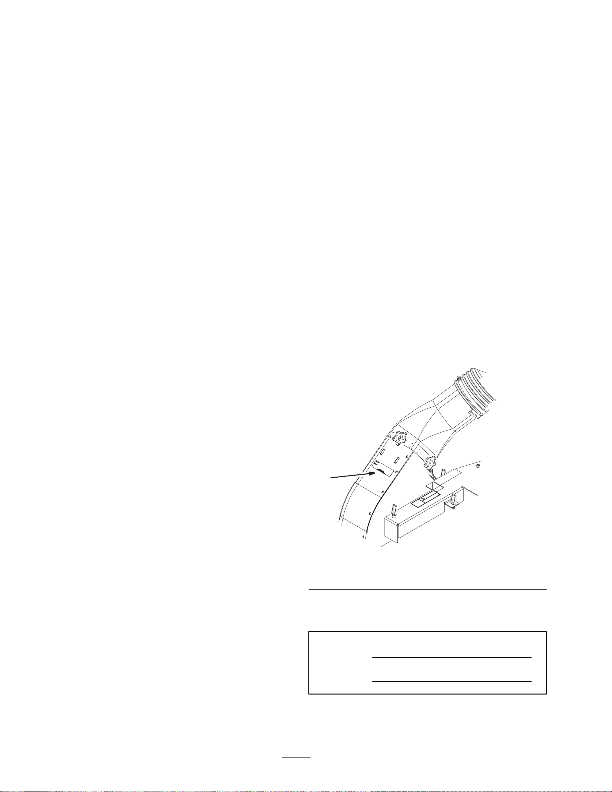
serial numbers of your product ready. Figure 1 illustrates
the location of the model and serial numbers on the
product.
1
m–6231
Figure 1
1. Location of the model and serial numbers
Write the product model and serial numbers in the space
below:
Model No.
Serial No.
2003 by The Toro Company
8111 Lyndale Avenue South
Bloomington, MN 55420-1196
All Rights Reserved
Printed in the USA
2

This manual identifies potential hazards and has special
safety messages that help you and others avoid personal
injury and even death. Danger, Warning, and Caution are
signal words used to identify the level of hazard. However,
regardless of the hazard, be extremely careful.
• If you remove the grass catcher, be sure to install any
discharge deflector or guard that might have been
removed to install the grass catcher. Do not operate the
mower without either the entire grass catcher or the
grass deflector in place.
Danger signals an extreme hazard that will cause serious
injury or death if you do not follow the recommended
precautions.
Warning signals a hazard that may cause serious injury or
death if you do not follow the recommended precautions.
Caution signals a hazard that may cause minor or moderate
injury if you do not follow the recommended precautions.
This manual uses two other words to highlight information.
Important calls attention to special mechanical
information and Note: emphasizes general information
worthy of special attention.
Safety
The following list contains safety information specific to
Toro products and other safety information you must know.
• Become familiar with the safe operation of the
equipment, with the operator controls, and safety signs.
• Use extra care with grass catchers or other attachments.
These can change the operating characteristics and the
stability of the machine.
• Turn off the engine and wait for all moving parts to
stop before removing the grass catcher or
unclogging the chute.
• Do not use your hands to unclog the chute, blower or
bagger.
• Do not leave grass in grass catcher for extended periods
of time.
• Grass catcher components are subject to wear, damage
and deterioration, which could expose moving parts or
allow objects to be thrown. Frequently check
components and replace with manufacturer’s
recommended parts, when necessary.
• Do not use a grass catcher on steep slopes. A heavy
grass catcher could cause loss of control or overturn the
machine.
• Slow down and use extra care on hillsides. Be sure to
travel in the recommended direction on hillsides. Turf
conditions can affect the machine’s stability. Use
extreme caution while operating near drop–offs.
• Keep all movement on slopes slow and gradual. Do not
make sudden changes in speed, directions or turning.
• The grass catcher can obstruct the view to the rear. Use
extra care when operating in reverse.
• Use care when loading or unloading the machine into a
trailer or truck
• Never operate with the discharge deflector raised or
removed and never altered, unless using a grass catcher
or mulching baffles.
• Keep hands and feet away from moving parts. Do not
make adjustments with the engine running.
• Stop on level ground, disengage drives, set the parking
brake, shut off the engine before leaving the operator’s
position for any reason including emptying the grass
catcher or unclogging the chute.
3

Safety and Instruction Decals
Safety decals and instructions are easily visible to the operator and are located near any area
of potential danger. Replace any decal that is damaged or lost.
79-0350
79-0360
1-653554
80-8040
88-8950
106-0871
98-4387
1. Warning—wear hearing protection.
93-1122
4

Setup
Note: Determine the left and right sides of the machine from the normal operating position.
Loose Parts
Note: Use the chart below to verify all parts have been shipped.
Important This kit and bagger will require significant time to install the first time. A right angle drill is recommended for
installation.
Step Description Qty. Use
1
2
3
4
5
Center rear baffle
Bolt, 5/16 x 5/8 inch
Flange nut, 5/16 inch
Left rear baffle
Bolt, 1/4 x 5/8 inch
Flange nut, 1/4 inch
Tunnel baffle—rear
Bolt, 5/16 x 5/8 inch
Flange nut, 5/16 inch
Bolt, 1/4 x 5/8 inch
Lock nut, 1/4 inch
Right rear baffle
Bolt, 1/4 x 5/8 inch
Flange nut, 1/4 inch
Tunnel baffle—front
Carriage bolt, 5/16 x 5/8 inch
Flange nut, 5/16 inch
1
5
5
1
3
3
1
2
2
1
1
1
2
2
1
3
3
Installing the center rear baffle
Installing the left rear baffle
Installing the rear tunnel baffle
Installing the right rear baffle
Installing the front tunnel baffle
6
7
8
9
10
Blade stiffener 3 Installing the blade stiffeners
No parts needed
Pulley assembly 1
Mounting plate
Bolt, 3/8 x 1–1/4 inch
Flange nuts, 3/8 inch
Template
Roller bushing
Bolt, 3/8 x 4–1/4 inch
5
2
4
4
1
1
1
Removing the existing mower pulley
assembly and the right rear gage wheel
Installing the pulley assembly, belt and
cover
Installing the mounting plates
Installing the gage wheel

Step UseQty.Description
11
12
13
14
15
No parts needed
No parts needed
Bagger mounting bracket
Left side bagger bracket
Right side bagger bracket
Bolt, 3/8 x 1 inch
Flange nut, 3/8 inch
Belleville washer, 3/8 inch
Blower assembly 1 Installing the blower assembly
Blower belt cover
Bagger Belt
Idler spring
Pulley cover
1
1
1
10
10
8
1
1
1
1
Installing the mower and PTO drive
belts
Removing the drive wheels and rear
bumper guard
Installing the bagger brackets
Installing the bagger belt and idler
spring
16
17
18
Hood assembly
Bag
Clevis pin
Hairpin cotter
Bagger tube support
Elbow
Bolt, 1/4 x 1–1/2 inch
Nut, 1/4 inch
Flat washer, 1/4 inch
Bagger tube
Clamp
Knob
Blower adapter
1
3
2
2
1
1
4
4
4
1
1
2
1
Installing the hood assembly and bags
Installing the bagger tube support and
elbow
Installing the bagger tube
6
Step UseQty.Description
Caster weight
U–bolt
Nut, 1/2 inch
Lock washer, 1/2 inch
19
20
Plate
Top weight
Bolt, 1/2 x 3 inch
Plate
No parts needed Adjusting the parking brake
Before Installation
Checking the Mower for
Existing Holes
Check for existing holes. Use any existing holes in the
mower that align the baffles in their correct positions.
2
2
4
4
Installing the weights
2
2
2
2
1
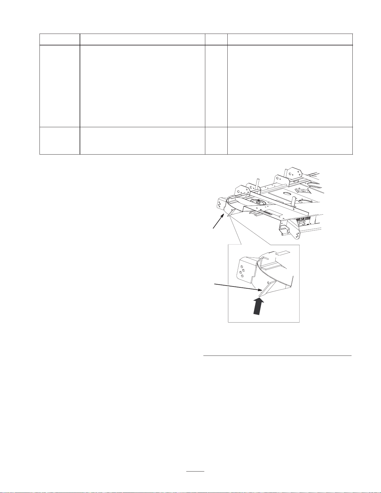
Removing the Grass Deflector
Bracket
Note: This section is only for mowers with grass deflector
bracket welded to the mower (Fig. 2).
1. Remove the grass deflector bracket from the mower as
shown in Figure 2. This will avoid any interference with
the rear tunnel baffle.
2. If you have a mower like the one shown in Figure 2,
contact an Authorized Service Dealer for a discharge
chute kit. This kit will allow you to install the bagger
and blower.
2
m–6169
Figure 2
1. Mower 2. Remove grass deflector
bracket
7
Removing the Mower
Note: If the mower is removed from the bottom bolts
attaching the chains to the mower, the mower will not need
to be leveled.
1. Remove the PTO drive belt from the rear idler arm
(Figures 3 and 5).
4
2
1
3
2
1
M–4417
Figure 3
1. Center bolt, spring loaded
idler
2. Alignment hole
2. Remove the PTO drive belt from the center mower
pulley (Fig. 5).
3. Remove PTO drive belt from the front fixed idler pulley
assembly (Figures 4 and 5).
3
2
1
m–6763
Figure 4
1. Center mower pulley
2. PTO Drive belt
3. Fixed idler pulley
assembly
m–4451
Figure 5
Top View
1. Center mower pulley
2. PTO Drive belt
3. Fixed idler pulley
assembly
4. Rear idler pulley
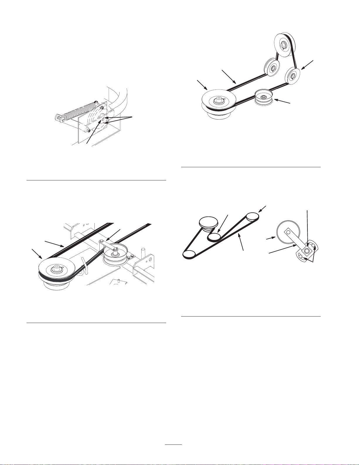
4. Loosen two nuts securing idler plate and move the idler
arm to relieve belt tension on the idler pulley (Fig. 29).
5. Remove the mower belt from the right side pulley.
5
4
6
6
2
1
M–4312
3
Figure 6
Top View
1. Mower Belt
2. Idler Arm
3. Idler nuts
4. Idler adjusting nut
5. Right side pulley
6. Idler pulley
6. Raise the mower with the height–of–cut lever.
7. Place wood blocks under the mower and lower the
mower onto the wood blocks.
Note: If the mower is removed from the bottom bolts
attaching the chains to the mower, the mower will not need
to be leveled.
8. Remove the four bolts at the bottom of the chains that
are attached to the mower (Fig. 7).
8
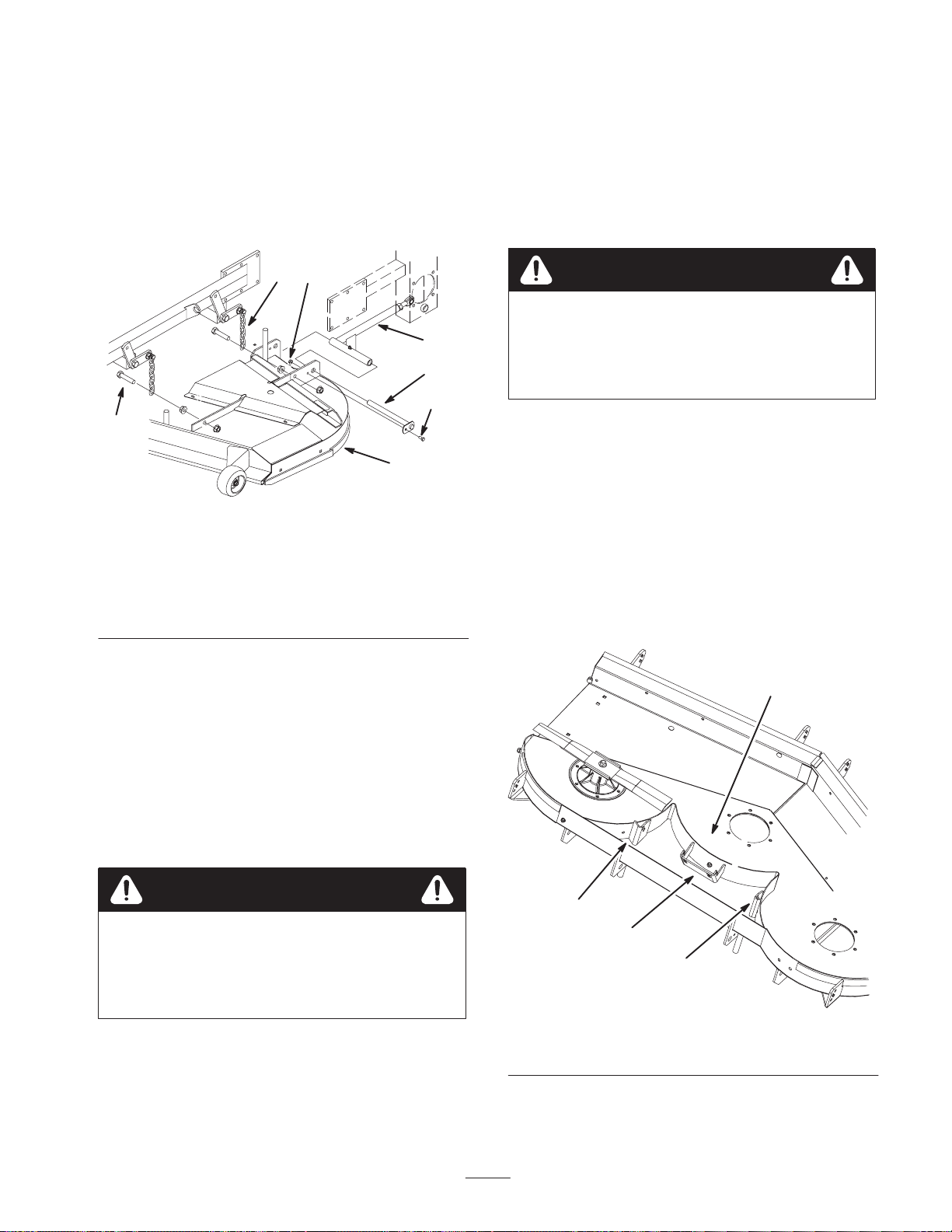
9. Remove the nuts and bolts holding the push arm pins
(Fig. 7).
Note: The gage wheels may need to be removed to allow
the push arm pins to be removed (Fig. 7).
10.Remove the push arm pins (Fig. 7).
Removing the Existing Blades
Note: In most mowing conditions, improved bagging
performance can be achieved by using bagging blades
(high lift). Contact an Authorized Service Dealer for the
proper blades for different mowing conditions.
11. Raise the height of cut lever and slide the mower out
from under the machine (Fig. 7).
2
6
4
7
5
3
1
M–4450
Figure 7
1. Mower
2. Chain
3. Chain Bolt
4. Push Arm
5. Push Arm Bolt
6. Push Arm Nut
7. Push Arm Pin
8. Gage wheel
9. Nut
1. Remove the existing blades from the spindles. Keep the
blade bolts for installing blades.
Warning
Contact with sharp blade can cause serious
personal injury.
• Wear gloves or wrap sharp edges of the
blade with a rag.
Removing the Cutting
Chamber Brackets
Note: This section is only for mowers with brackets welded
to the cutting chamber (Fig. 8).
1. Remove the three cutting chamber brackets from the
mower (Fig. 8).
2. Grind the welds flat on rear part of the cutting
chambers. This will allow the correct fit for the cutting
chamber baffles.
Preparing the Mower
1. Tip the mower upside down and block up ends to ease
installation of components.
2. Thoroughly clean the mower. All debris must be
removed to ensure baffles will fit properly against the
mower.
3. Repair all bent or damaged areas of the mower and
replace any missing parts.
Warning
Contact with sharp blade can cause serious
personal injury.
• Wear gloves or wrap sharp edges of the blade
with a rag.
1
2
2
2
m–6159
Figure 8
1. Cutting chamber 2. Cutting chamber stiffener
9
Step
1
Parts needed for this step:
• 1 Center cutting chamber baffle
1
2
• 5 Bolts, 5/16 x 5/8 inch
• 5 Flange nuts, 5/16 inch
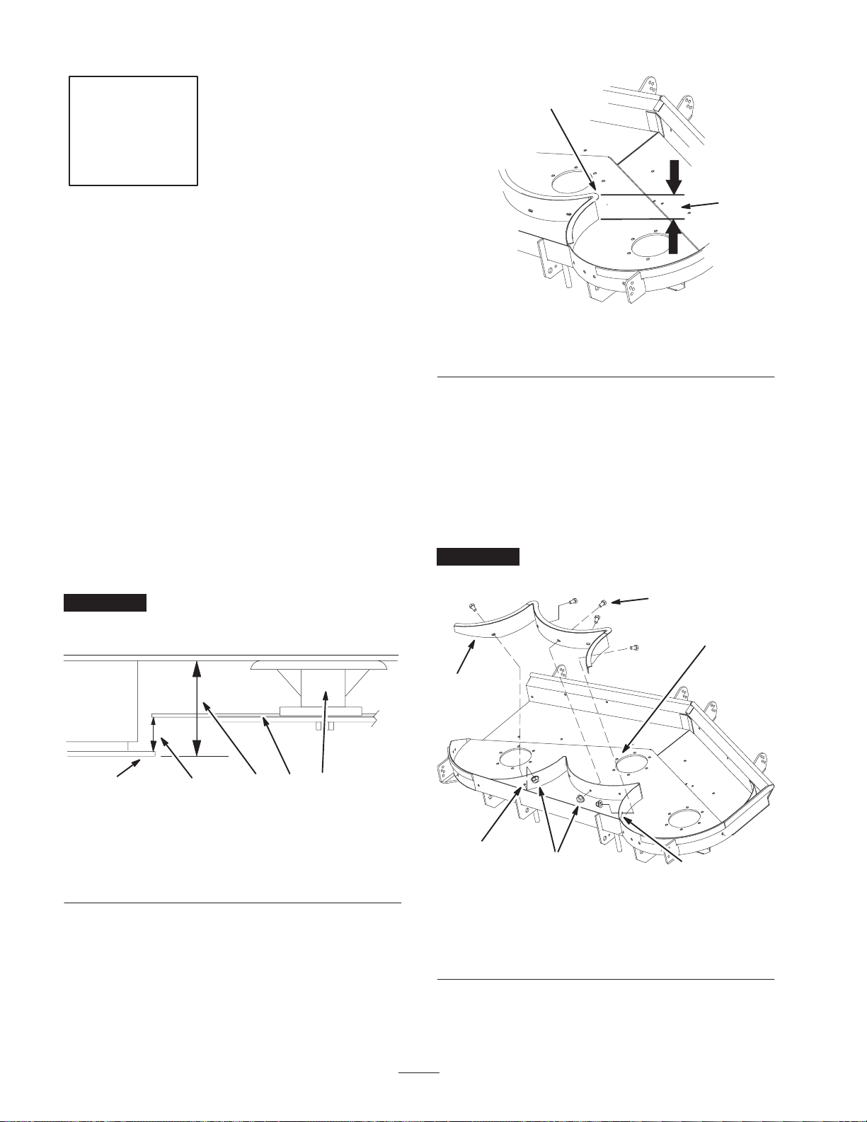
Installing the Center Rear
Baffle
A right angle drill will be needed to perform this
installation.
Note: If present, use existing holes for installing this baffle.
Make sure the existing holes match the holes in the baffle.
1. Place the center rear baffle behind the rear cutting blade
chamber (Fig. 11).
2. Align the center rear baffle so the baffle flange is
3–5/8 in. (92 mm) from the top of the cutting chamber
(Figures 9 and 11).
Important Make sure the baffle flange is 3–5/8 inch
(92 mm) from the top of the cutting chamber at all
locations (Figures 9 and 13).
m–6774
Figure 10
1. Baffle flange 2. Baffle to top of cutting
chamber, 3–5/8 in.
3. Clamp the center baffle in place, tightly against the
cutting chamber.
4. Using the baffle as a template, mark, center punch and
drill 1/8 inch pilot holes at the 5 locations (Fig. 11).
5. Drill 11/32 inch dia. holes through the pilot holes
(Fig. 11).
Install the center baffle with 5 bolts (5/16 x 5/8 inch) and 5
flange nuts (5/16 inch) (Fig. 11).
Important Make sure the bolt heads are installed on the
inside of the cutting chamber. See figure 11.
5
3
1
154 32
1. Baffle flange
2. Blade
3. Spindle
Figure 9
4. Blade clearance,
1/2 ±1/16 in.
5. Baffle to top of cutting
chamber, 3–5/8 in.
m–5942
2
1. Center Baffle
2. Hole to drill
3. Center cutting blade
chamber
10
4
Figure 11
2
4. Flange nuts, 5/16 inch
5. Bolt, 5/16 x 5/8 inch
m–6775
Step
2
Parts needed for this step:
• 1 Left rear baffle
• 3 Bolts, 1/4 x 5/8 inch
• 3 Flange nuts, 1/4 inch
2. Align the left rear baffle within 3/16 inch and flush with
the bottom of the center baffle (Fig. 13).
3. Position the left rear baffle so the baffle flange is
3–5/8 in. (92 mm) from the top of the cutting chamber
(Fig. 9).
Important Make sure the baffle flange is 3–5/8 inch
(92 mm) from the top of the cutting chamber at all
locations (Fig. 9).
Note: If 3–5/8 inch (92 mm) can not be achieved, the
bottom welds have to be ground down. Refer to Grinding
the Welds on page 11.
4. Clamp the baffle in place.
5. Using the baffle as a template, drill three, 9/32 inch
diameter, holes into the left cutting chamber (Fig. 14).
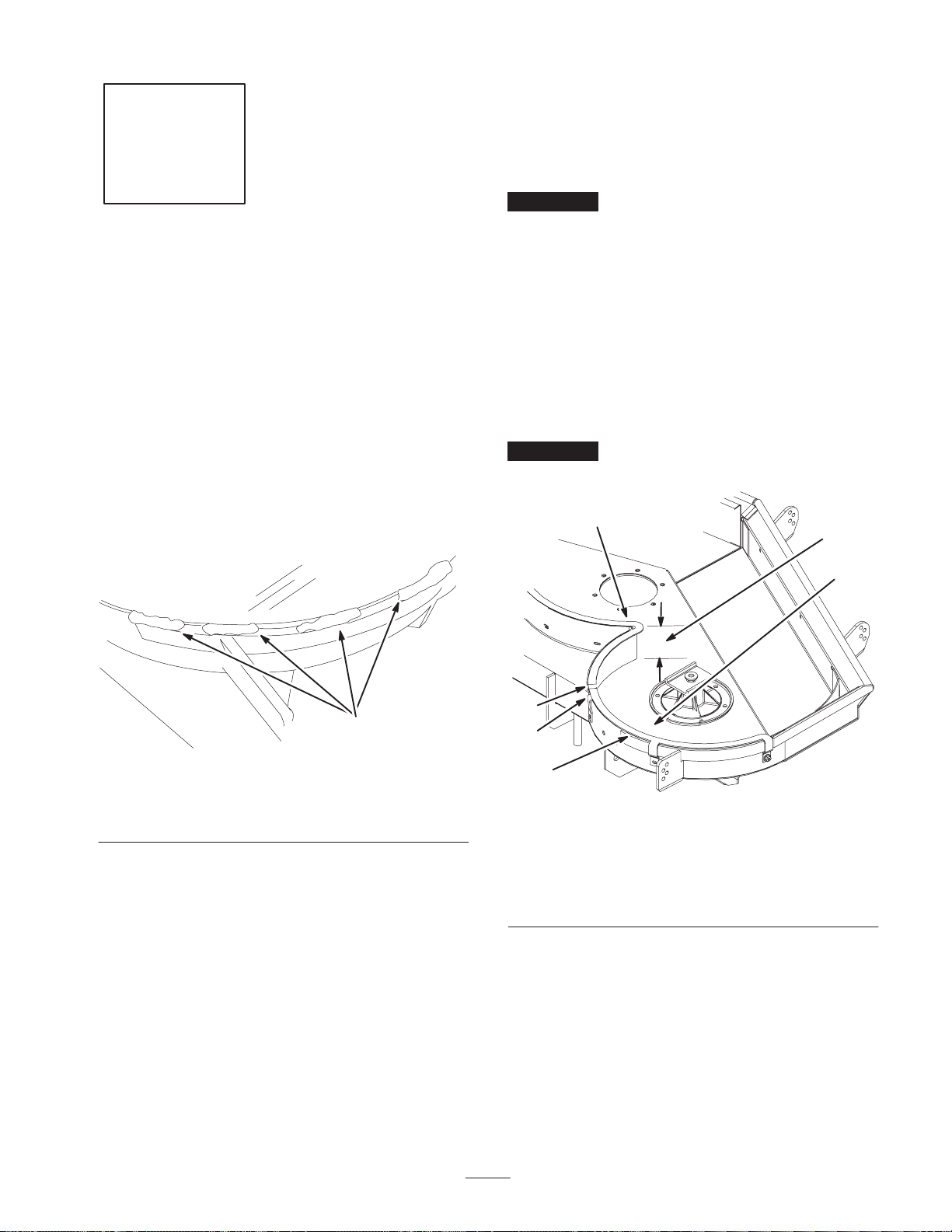
Grinding the Welds
Note: If 3–5/8 inch (92 mm) can not be achieved when
installing the left and right rear baffles, the bottom welds
need to be ground down.
1. Grind the welds flat on rear part of the mower. This will
allow the correct fit for the left and right rear baffles
(Fig. 12).
1
m–5877
Figure 12
1. Grind welds flat
Installing the Left Rear Baffle
1. Place the left rear baffle behind the left cutting chamber
(Fig. 13). The tabs will mount on the outside of the
mower.
6. Install the left baffle with 3 bolts (1/4 x 5/8 inch) and 3
flange nuts (1/4 inch) (Fig. 14).
Important Make sure the bolt heads are installed on the
inside of the cutting chamber. See figure 14.
1
5
4
6
3
2
1. Center Baffle
2. Left baffle
3. Flush with bottom of
center baffle
4. Left cutting chamber
Figure 13
5. Baffle flange to top of
cutting chamber, 3–5/8 in.
(92 mm)
6. 0 to 3/16 inch gap
m–5874
11
m–6773
3
1
8
Step
6
4
5
1. Left rear baffle
2. Left side of mower
3. Bolt, 1/4 x 5/8 inch
4. Flange nut, 1/4 inch
4
Figure 14
5. Hole to drill
6. Rear center baffle
7. Cutting chamber
8. Tab
7
3
Parts needed for this step:
• 1 Tunnel baffle—rear
• 2 Bolts, 5/16 x 5/8 inch
4
2
5
• 2 Flange nuts, 5/16 inch
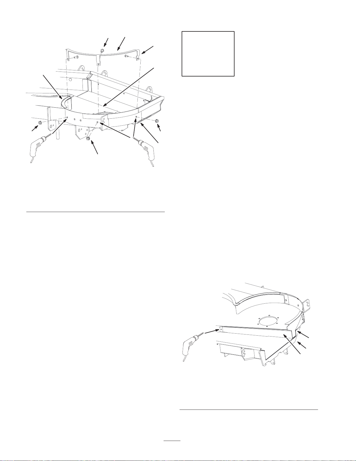
Installing the Rear Tunnel
Baffle
1. Place the rear tunnel baffle against the rear wall of the
discharge tunnel (Fig. 16).
Note: The rear tunnel baffle must not extend past the
outside of the mounting bracket.
2. Align the rear tunnel baffle, flush with the outside of the
mounting bracket (Fig. 16).
3. Clamp the baffle in place.
4. Using the baffle as a template, mark, center punch and
drill 1/8 inch pilot holes at the 3 locations in Figures 15,
16, and 17.
5. Remove the clamp.
6. Drill two, 11/32 inch diameter, holes through the pilot
holes along the tunnel (Figures 15 and 16).
m–6768
4
Figure 15
1. Rear tunnel baffle
2. Mounting bracket
3. Flush edge with outside of
mounting bracket
4. Drill an 11/32 inch hole
here
2
1
3
12

Step
2
1
m–6767
Figure 16
1. Rear tunnel baffle 2. Drill an 11/32 inch hole
7. Drill a, 9/32 inch diameter, hole through the side of the
right cutting chamber (Fig. 17).
8. Install the rear tunnel baffle to the mower with
2 carriage bolts (5/16 x 5/8 inch) and 2 flange nuts
(5/16 inch) (Fig. 17).
Important Make sure the bolt heads are installed on the
inside of the cutting chamber.
here
1
2
4
Parts needed for this step:
• 1 Right rear baffle
• 3 Bolts, 1/4 x 5/8 inch
• 3 Flange nuts, 1/4 inch
Installing the Right Rear Baffle
1. Place the right baffle behind the right cutting chamber
(Fig. 18). The tabs will mount on the outside of the
mower.
2. Align the right baffle against and flush with the bottom
of the center baffle (Fig. 18).
3. Position the left rear baffle so the baffle flange is
3–5/8 in. (92 mm) from the top of the cutting chamber
(Fig. 9).
Important Make sure the baffle flange is 3–5/8 inch
(92 mm) from the top of the cutting chamber at all
locations (Fig. 9).
2
3
4
m–6769
1. Rear tunnel baffle
2. Bolt, 5/16 x 5/8 inch
3. Flange nut, 5/16 inch
Figure 17
4. Tunnel rear wall
5. Drill a 9/32 inch hole here
6. Side of cutting chamber
Note: If 3–5/8 inch (92 mm) can not be achieved, the
bottom welds have to be ground down. Refer to Grinding
the Welds on page 11.
6
3
5
4. Clamp the baffle in place.
5. Using the baffle as a template, drill three, 9/32 inch
diameter, holes into the right cutting blade chamber
(Fig. 19).
6. Install the right baffle with 2 bolts (1/4 x 5/8 inch) and
2 flange nuts (1/4 inch) (Fig. 19).
Important Make sure the bolt heads are installed on the
inside of the cutting chamber.
7. Install the right rear baffle to the rear tunnel baffle with
a bolt (1/4 x 5/8 inch) and a flange nut (1/4 inch)
(Fig. 19).
13

2
3
1. Center Baffle
2. Right baffle
1
3
2
4
Figure 18
m–6813
3. Flush with center baffle
4. Right cutting chamber
Step
5
1
Parts needed for this step:
• 1 Tunnel baffle—front
• 3 Carriage bolts, 5/16 x 5/8 inch
• 3 Flange nuts, 5/16 inch
Installing the Front Tunnel
Baffle
1. Remove the existing right front blowout baffle. Save
baffle and hardware for use when bagging baffles are
removed.
2. Place the front tunnel baffle against the the front wall of
4
3
the discharge tunnel. (Fig. 20).
3. Align the front tunnel baffle flush with the outside of
the mounting bracket (Figures 20 and 21).
6
4
1. Right baffle
2. Right side of mower
3. Bolt, 1/4 x 5/8 inch
5
Figure 19
4. Flange nut, 1/4 inch
5. Holes to drill
6. Rear tunnel baffle
m–6770
1
3
2
Figure 20
1. Front tunnel baffle
2. Flush edge with mounting
bracket
m–6764
3. Front tunnel wall
14

Bottom View
2
1
2
3
3
2
4
m-5958
Figure 21
1. Front tunnel baffle
2. Mounting bracket
3. Flush edge with mounting
bracket
4. Grass deflector
4. Clamp the baffle in place.
5. Using the baffle as a template, mark, center punch and
drill 1/8 inch pilot holes at the 3 locations (Fig. 22).
6. Remove the clamp.
7. Remove the baffle and drill two, 11/32 inch diameter,
through the pilot holes in the top of the mower
(Fig. 22).
1
4
6
3
1. Front tunnel baffle
2. Carriage Bolt, 5/16 x
5/8 inch
3. Nut, 5/16 inch
5
Figure 22
4
m–6765
4. Hole to drill
5. Front wall
6. Mounting bracket
8. Drill one, 11/32 inch diameter, hole through the pilot
hole in the side of the discharge tunnel (Fig. 22).
9. Install the front tunnel baffle with 3 carriage bolts
(5/16 x 5/8 inch) and 3 flange nuts (5/16 inch) (Fig. 22).
15

Step
Step
6
Parts needed for this step:
• 3 Blade stiffeners
Installing the Blade Stiffener
Note: In most mowing conditions, improved bagging
performance can be achieved by using bagging blades
(high lift). Contact an Authorized Service Dealer for the
proper blades for different mowing conditions.
1. Install the blade onto the spindle shaft (Fig. 23).
Important The sail, or the curved part of the blade,
must be pointing upward toward the inside of the mower to
ensure proper cutting.
2. Install the blade stiffener, the spring disk and the blade
bolt (Fig. 23). Torque the blade bolt to 85–110 ft-lb
(115–150 Nm).
3. Rotate the blades to ensure there is clearance between
the blade tips and the baffles.
7
No Parts needed for this step.
Removing the Existing Mower
Pulley and Right Rear Gage
Wheel
Note: Clean the area around pulley before removing pulley
assembly. Hold spindle up from underneath the deck. It can
fall when nut and washer are removed.
1. Turn the mower over.
2. Remove the right belt cover from the mower and
discard.
3. Remove the nut and washer on top of the spindle
(Fig. 25). Save the nut and washer.
4. Remove the existing pulley assembly.
5. Remove the existing gage wheel from the right rear of
the mower (Fig. 24).
4. If contact is made, do not use the mower. Check and
make sure the baffles are installed properly.
Important Do not use the mower if blades contact the
baffles.
3
5
4
1
1. Sail Area of Blade
2. Blade
3. Spring Disk
4
Figure 23
4. Blade Bolt
5. Cone Towards Bolt Head
6. Stiffener
2
6
3
m–6728
6. Remove the gage wheel from the stud by removing the
nut and washer (Fig. 24).
4
3
2
1. Gage wheel
2. Stud
3. Spring disk
Figure 24
4. Flange nut
5. Nut and washer—retain
1
5
m–4161
16

Step
Step
8
Parts needed for this step:
• 1 Pulley assembly
Installing the Pulley Assembly
1. Install new pulley assembly onto the spindle. Install it
so the large pulley is on the bottom (Fig. 25).
2. Install the washer and nut (Fig. 25).
Important Tighten the nut to 115 ft–lb ± 15 ft–lb
torque.
3. Grease the spindle to fill bearings with grease.
1
2
3
4
7
6
9
Parts needed for this step:
• 2 Mounting plates
• 1 T emplate
• 4 Bolts, 3/8 x 1–1/4 inch
• 4 Flange nuts, 3/8 inch
Installing the Mounting Plates
Drilling the Holes into the Mounting
Bracket
This kit contains a metal template for locating the mounting
bracket holes to drill.
1. Remove the grass deflector from the mower (Fig. 57).
2. Remove the existing right rear gage wheel (Fig. 57).
5
1. Nut
2. Washer
3. Pulley Assembly
4. Blade spindle
Figure 25
5. Mower
6. Lower pulley
7. Upper pulley
m–6793
3. Position the template onto the the mounting bracket and
align with the top and sides of the mounting bracket.
(Fig. 26).
4. Clamp the template to the mounting bracket (Fig. 26).
5. Mark and center punch the 4 holes and remove the
template (Fig. 26).
6. Drill 1/8 inch pilot holes at the 4 marked locations and
then drill 7/16 or 1/2 inch diameter holes.
7. File the metal burrs from the drilled holes.
3
1
holes
2
m–6752
3
1. Template
2. Mounting bracket
Figure 26
3. Mark and center punch
17

Installing the Mounting Plates
1. Install the mounting plates to the inside of the mounting
bracket with 4 bolts (3/8 x 1–1/4 inch) and 4 flange nuts
(3/8 inch) (Fig. 27).
1
1
3
Step
10
Parts needed for this step:
5
4
2
Figure 27
1. Mounting plate
2. Bolt, 3/8 x 1–1/4 inch
3. Flange nut, 3/8 inch
2. When the bagger is to be used for dedicated bagging,
leave the grass deflector off the machine.
Important Remember to install the grass deflector
when changing to side discharge mode.
3. When the mower is switched between bagging and side
discharge frequently, leave the grass deflector on the
machine. The grass deflector will rest against the
blower belt cover.
4. Mounting bracket
5. Drill 7/16 inch holes
m–6785
• 1 Bolt, 3/8 x 4–1/4
• 1 Roller bushing
Installing the Gage Wheel
1. Install the gage wheel to the new mounting plate with a
new bolt (3/8 x 4–1/4 inches), new roller bushing,
existing flat washer, and existing nut (Fig. 29).
Note: The roller bushing and bolt replace the existing gage
wheel stud (3/8 x 4–1/4 inches).
5
6
1
3
Figure 28
4
4. Gage wheel
5. Flat washer
6. Nut
m–6784
1. Mounting plate
2. Bolt, 3/8 x 4–1/4 inch
3. Roller bushing
2
18

Step
6
4
6
5
11
Installing the Mower and PTO
Drive Belts
Installing the Mower Belt
1. Install the mower belt around the spindle pulleys, belt
guide, the idler pulley, and in the lower groove of the
center and right side spindle pulleys (Fig. 29).
2. Using a socket and torque wrench, rotate the idler
adjusting nut until the torque is 25–30 ft–lb
(34–41 Nm). Tighten the two idler nuts.
1
4
3
m–4451
1. Clutch
2. Clutch retaining strap
3. Clutch terminal
4. PTO belt
2. Check the belt tension. The center bolt of the spring
loaded idler must be between the two alignment holes in
left support plate (Fig 31).
Note: Check position of center bolt in Low Height of Cut.
The center bolt must be at or below the top alignment hole.
Check position of center bolt in a High Height of Cut. The
center bolt must be at or above the lower adjustment hole
(Fig 31).
7
1
2
M–4373
Figure 30
5. Machine frame
6. 1/4 inch Belt Twist
7. 1/8 inch Belt Twist
2
M–4312
Figure 29
Top View
1. Deck Belt
2. Idler Arm
3. Idler nuts
4. Idler adjusting nut
Replacing the PTO Drive Belt
1. Install the drive belt over the clutch, around the rear
idler pulley, installed into the idler arm assembly,
installed into the fixed idler pulley assembly and onto
the top center pulley (Figures 4 and 30).
Important Check the amount of twist in belt between
pulleys. Make sure it is only what is specified in figure 30.
3
2
1
Figure 31
1. Center bolt, spring loaded
idler
3. If adjustment is required, loosen the fixed idler on right
support plate and move up or down in adjustment slot.
To relieve belt tension lift up on spring loaded idler.
2. Alignment hole
M–4417
19

Step
1
Figure 32
1. Fixed Idler 2. Adjustment slot
4. Check belt tension again. The center bolt of spring
loaded idler must be between the two alignment holes in
left support plate (Fig 31). Adjust, if necessary, and
tighten all hardware securely.
5. Rotate the belt guide, on rear of the mower, so it is
1/8–1/4 inch (3–7 mm) away from the vertical side of
the PTO belt (Fig. 33).
1
2
2
12
No parts needed for this step.
m–3746
Removing the Drive Wheels
and Bumper Guard
Danger
Mechanical or hydraulic jacks may fail to support
machine and cause a serious injury.
• Use jack stands when supporting machine.
• Do not use hydraulic jacks.
1. Remove the existing rear bumper guard (Fig. 34).
3
1. Belt guide
2. PTO Drive belt
Figure 33
3. 1/8–1/4 inch (3–7 mm)
M–4374
3
m–6794
Figure 34
1. Rear bumper guard
2. Bolt
2. Loosen the drive wheel lugs or nuts.
3. Raise the rear of the machine and support with jack
stands.
4. Remove the drive wheels.
1
3. Nut
2
20

Step
13
1
3
2
Parts needed for this step:
• 1 Left side bagger bracket
• 1 Right side bagger bracket
• 1 Bagger mounting bracket
• 10 Bolts, 3/8 x 1 inch
• 10 Flange nuts, 3/8 inch
• 8 Belleville washers, 3/8 inch
Installing the Bagger Brackets
Installing the Left and Right Side
Brackets
Important Do not tighten any bolts until both side
brackets and bagger mounting bracket are fit loose on the
machine.
Refer to Tightening the Mounting Bolts, on page 22, for the
correct procedure to tighten the bolts.
1. Using the existing holes, install the side bagger bracket
to the side of the machine frame with 2 bolts
(3/8 x 1 inch), 2 flat washers (3/8 inch) and 2 flange
nuts (3/8 in.) (Fig. 35).
2. Repeat the previous step for the opposite side.
6
5
1. Bagger bracket—left side
shown
2. Bolt, 3/8 x 1 inch
3. Flange nut, 3/8 inch
4
Figure 35
4. Machine side frame
5. Existing hole
6. Belleville washer, 3/8 inch
2
m–6742
Installing the Bagger Mounting Bracket
Important Do not tighten any bolts until both side
brackets and bagger mounting bracket are fit loose on the
machine.
Important Make sure the bagger mounting bracket is
installed in the position shown in Figure 36.
1. Remove the existing two bolts in the bottom of the rear
frame (Fig. 36).
2. Install the bagger mounting bracket to the left and right
side bagger brackets with 4 bolts (3/8 x 1 inch),
4 Belleville washers (3/8 inch) and 4 flange nuts
(3/8 in.) (Fig. 36).
3. Install the bagger mounting bracket to the rear frame of
the machine with 2 bolts (3/8 x 1 inch) and 2 flange
nuts (3/8 in.) (Fig. 36).
1
21

2
4
6
1. Bagger mounting bracket
2. Bolt, 3/8 x 1 inch
3. Flange nut, 3/8 inch
4. Belleville washer, 3/8 inch
5
Figure 36
3
6
4
3
5. Rear frame
6. Existing bolts located
here
2
1
2
Step
14
Parts needed for this step:
• 1 Blower assembly
Installing the Blower Assembly
m–6743
Important Make sure the mounting plate is installed to
the mower. Refer to the Finishing Kit.
1. Disengage the PTO and set the parking brake.
2. Stop the engine, remove the key, and wait for all
moving parts to stop before leaving the operating
position.
3. Raise the grass deflector.
Tightening all the Mounting Bolts
The following steps are the correct sequence to tighten the
side brackets and the bagger mounting bracket.
All mounting bolts need to be torqued to 35 ft–lb
(48 Nm).
1. Tighten the bagger mounting bracket to the rear frame
first (Fig. 36).
2. Tighten the bagger mounting bracket to the side
brackets (Fig. 36).
3. Tighten the side brackets to the side of the mower
(Fig. 35).
4. Install the drive wheels and torque to 95 ft-lb
(128 NM).
5. Lower the machine onto the drive wheels.
4. Slide the blower assembly peg into the hole on the
mounting plate (Fig. 37).
2
3
1
5
4
Figure 37
1. Mower
2. Blower assembly
3. Blower assembly peg
5. Close the blower assembly. (Fig. 42).
4. Mounting plate hole
5. Mounting plate
m–6747
6. Check if the latch fully engages the front latch peg.
Refer to Checking and Adjusting the Blower Latch on
page 36.
Note: There needs to be a little or no gap between the
blower assembly and the mounting plate.
22

Step
15
6. Install the new belt cover over the pulley assembly and
secure the latches (Fig. 39).
1
Parts needed for this step:
• 1 Blower belt cover
• 1 Idler spring
• 1 Bagger belt
• 1 Pulley cover
Installing the Bagger Belt and
Idler Spring
Important The idler spring and bagger belt need to be
installed together.
This will create slight tension on both the spring and belt
while installing them.
1. Disengage the PTO and set the parking brake.
2. Stop the engine, remove the key, and wait for all
moving parts to stop before leaving the operating
position.
3. Slide the spring into the blower eyebolt (Fig. 38).
2
Figure 39
1. Belt cover 2. Latch
7. Install the bagger belt between the top mower pulley
and the belt cover (Fig. 40).
3
4
2
m–6755
1
5
4. Install the spring into the idler arm eyebolt (Fig. 38).
5
4
2
3
1
m–6276
Figure 38
1. Idler spring
2. Blower assembly
3. Idler arm eyebolt
5. Push down on the front latch (colored red) and open the
blower assembly (Fig. 41).
4. Blower eyebolt
5. Idler arm
1
3
Figure 40
1. Mower belt cover
2. Blower assembly
3. Top mower pulley
8. Route the bagger belt around the top pulley of the
mower pulley assembly (Fig. 41).
9. Feed the belt between the idler pulleys (Fig. 41).
4. Bagger belt
5. Bagger belt—installed
2
m–6731
23

10.Route the bagger belt around the spring–loaded idler
pulley (Fig. 41). The backside of belt will be touching
the pulley.
11. Route the bagger belt around the fixed idler pulley
(Fig. 41).
12.Route the bagger belt around the blower pulley
(Fig. 41).
15.Install the belt cover over the pulley assembly and
secure the 3 cover latches into the blower (Fig. 43).
3 2
3
6
4
7
1
5
m–6732
2
Figure 41
1. Blower pulley
2. Mower
3. Blower assembly
4. Top pulley of mower
pulley assembly
5. Spring loaded idler pulley
(belt back side touching
pulley)
6. Fixed idler pulley
7. Front latch (colored red)
13.Close the blower assembly and ensure the blower front
latch engages onto the front peg (Fig. 42).
1
1. Blower assembly
2. Blower belt cover
m–6236
Figure 43
3. Latch
1
2
m–6732
Figure 42
1. Blower front latch (Red) 2. Front peg
Important Make sure to check the belt and spring
length after the initial 8 hours of use.
14.Adjust the bagger belt tension. Refer to Checking and
Adjusting the Bagger Belt Tension on page 35.
24

Step
Step
16
Parts needed for this step:
• 1 Tube support
• 1 Elbow
• 4 Bolts, 1/4 x 1–1/2 inch
• 4 Nuts, 1/4 inch
• 4 Flat washers, 1/4 inch
Installing the Bagger Tube
Support and Elbow
1. Position the elbow inside the bagger hood (Fig. 44).
2. Install the elbow and tube support to the bagger hood
with 4 bolts (3/8 x 5/8 inch), 4 washers (3/8 inch), and
4 nuts (3/8 inch) (Fig. 44).
6
5
6
2
17
Parts needed for this step:
• 1 Hood assembly
• 3 Bags
• 2 Clevis pins
• 2 Hairpin cotter pins
Installing the Hood Assembly
and Bags
Warning
Components around engine will be hot if the
machine has been running. Touching hot
components can cause burns.
• Do not touch engine components when hot.
• Allow engine to cool before performing
maintenance.
3
4
1. Tube support
2. Elbow
3. Bagger hood
1. Install the hood assembly onto the bagger mounting
bracket (Fig. 45).
1
m–6730
Figure 44
4. Nut, 1/4 inch
5. Flat washer, 1/4 inch
6. Bolt, 1/4 x 1–1/2 inch
1. Hood assembly 2. Bagger mounting bracket
2
1
m–6740
Figure 45
25

2. Install the 2 clevis pins into the hood assembly and
bagger mounting bracket. Secure it with 2 hairpin cotter
pins (Fig. 46).
4. Lower the bagger hood over the bags.
1
1
2
4
3
m–6741
Figure 46
1. Hood assembly
2. Bagger mounting bracket
3. Hairpin cotter pin
4. Clevis pin
3. Install the bag tab into the notch in the hood assembly
(Fig. 47). Do this for all the bags.
Note: The bag will rest on the bagger frame (Fig. 47).
1
4
3
2
3
3
4
2
4
m–6719
Figure 48
1. Hood
2. Bags
3. Bagger latch
4. Latch hook
5. Position the bagger latch under the latch hook
(Figures 48 and 49).
6. Push down on the bagger latch until it locks into place
(Fig. 49).
1
2
1. Hood assembly
2. Bag
3. Bag tab
m–6264
Figure 49
1. Bagger latch 2. Latch hook
5
2
m–6718
Figure 47
4. Notch
5. Bagger frame
26

Step
18
4
1
3
5
4
Parts needed for this step:
• 1 Bagger tube
• 1 Clamp
• 2 Knobs
• 1 Blower adapter
Installing the Bagger Tube
Note: To ease assembly of the bagger tube to the blower
adapter, apply soapy water to both the bagger tube and the
adapter.
1. Install one end of the tube, 4 to 4–1/2 inches (102 to
114 mm) onto the blower adapter and secure it with a
clamp (Fig. 50).
5
4
2
m–6252
Figure 51
1. Tube
2. Blower assembly
3. Top blower stud
Note: There are nubs on the inside of the bagger elbow that
hold the upper end of the bagger tube (Fig. 52).
4. Place the upper tube into the bagger elbow (Fig. 52).
5. Move the upper tube back and forth, until at least two
ribs engage into the nubs inside the bagger elbow.
6. Make sure the tube rests on the tube support (Fig. 52).
2
1
4. Knob
5. Side blower stud
5
3
6
4
1
3
2
Figure 50
1. Tube
2. Blower adapter
3. Clamp
4. 4 to 4–1/2 inches (102 to
114 mm)
2. Place the blower adapter over the top blower stud and
slide it into the side stud (Fig. 51).
3. Install the knobs onto the top and side stud (Fig. 51).
This will secure the lower tube end to the blower
assembly.
5. Tube installed onto the
adapter 4 to 4–1/2 inches
(102 to 114 mm)
m–6815
m–6728
1. Tube
2. Bagger hood
3. Nubs
27
Figure 52
4. Ribs
5. Elbow
6. Tube support

Step
19
2
1
3
6
1
Parts needed for this step:
• 2 Caster weights
• 2 Top weights
• 2 U–bolts
• 4 Nuts, 1/2 inch
• 2 Plates
• 4 Lock washers, 1/2 inch
• 2 Bolts, 1/2 x 3 inch
Installing the Weights
To comply with ANSI/OPEI B71.4–1999 Standard, weights
must be added to the machine.
Installing the Caster Weights
Caution
The bagger adds a lot of weight to the rear of the
machine and may cause an unstable condition
which could result in a loss of control.
4
5
m–5882
Figure 53
1. Front caster weight
2. U–bolt
3. Plate
4. Nut
5. Front caster
6. Lock washer
Installing the Extra Top Weight
1. Install the top weight on top of the caster weight with a
bolt (1/2 x 3 inch) (Fig. 54).
2
1
3
• Install the front caster weights and top weights.
1. Place a caster weight on the front caster and install the
U–bolt through the caster weight (Fig. 53).
2. Install the plate, the nuts (1/2 inch) and the lock washer
(1/2 inch) under the frame and caster weight (Fig. 53).
3. Repeat for the opposite side.
1. Top weight
2. Bolt
28
4
m–6756
Figure 54
3. Front caster weight
4. Front caster wheel

Checking the Tire Pressure
Check and adjust the air pressure in the front and rear tires.
Front tire pressure: 25 psi (172 kPa) (Fig. 54).
4
7
5
6
Rear tire pressure: 20 psi (140 kPa) (Fig. 55).
1
Figure 55
1. Valve
stem
Check the Level of the Mower
Refer to the mower Operator’s Manual for the correct
procedure.
m–1872
1
2
3
Figure 56
1. Brake lever
2. Spring 2–5/8 inch
(67 mm)
3. Adjusting nut and jam nut
below the spring
3. If adjustment is necessary, loosen the jam nut below the
spring and adjust the nut directly below the spring
(Fig. 56).
4. Turn the nut until the correct measurement is obtained.
Turn the nut clockwise to shorten the spring length and
turn them counterclockwise to lengthen the spring.
5. Tighten the two nuts, below the spring, together and
repeat on the opposite side of the machine.
4. Collar on brake rod
5. 5/16 inch (8 mm)
6. Yoke and jam nut
7. Trunnion roller
m–3788
Step
20
No parts needed for this step.
Adjusting the Parking Brake
Check the parking brake for proper adjustment.
1. Disengage the brake lever (lever down).
2. Measure the length of the spring. The measurement
should be 2–5/8 inch (67 mm) between the washers
(Fig. 56).
6. Engage the parking brake (lever up).
7. Measure the distance between the trunnion roller and
the collar on brake rod. The measurement needs be
5/16 inch (8 mm) (Fig. 56).
8. If adjustment is necessary, loosen the jam nut directly
next to the yoke. Turn the nuts below the spring until
the correct measurement is obtained (Fig. 56).
9. Tighten the jam nut next to the yoke and repeat on the
opposite side of the machine.
29

Using the Grass Deflector
Installing the Grass Deflector
Note: Make sure the grass deflector is installed when the
bagger and tubes are removed.
Warning
Without the grass deflector, bagger tubes or
complete bagger assembly mounted in place, you
and others are exposed to blade contact and
thrown debris. Contact with the rotating mower
blade(s) and thrown debris will cause injury or
death.
• Always install the grass deflector when
removing the bagger and changing to side
discharge mode.
• If the grass deflector is ever damaged, replace it
immediately. The grass deflector routes material
down toward the turf.
• Never put your hands or feet under the mower.
• Never try to clear the discharge area or mower
blades unless you move the power take off
(PTO) to off and rotate the ignition key to off.
Also remove the key and pull the wire off of the
spark plug(s).
1. When the bagger is to be used for dedicated bagging,
leave the grass deflector off the machine.
Important Remember to install the grass deflector
when changing to side discharge mode.
2. When the mower is switched between bagging and side
discharge frequently, leave the grass deflector on the
machine. The grass deflector will rest against the
blower belt cover.
Note: Make sure the grass deflector is installed when the
bagger and tubes are removed.
The grass deflector spring will have either an L end or a
straight end (Fig. 57).
Warning
An uncovered discharge opening could allow the
lawn mower to throw objects in the operator’s or
bystander’s direction and result in serious injury.
Also, contact with the blade could occur.
Never operate the lawn mower unless you install a
cover plate, a mulch plate, grass deflector or a
grass chute and catcher.
1. Place spacer and spring onto grass deflector. Place the L
or the straight end of spring behind deck edge.
Note: Make sure the L or the straight end of spring is
installed behind deck edge before installing the bolt as
shown in figure 57.
2. Install bolt and nut. Place J hook end of spring around
grass deflector (Fig. 57).
Important The grass deflector must be lowered down
into position. Lift the deflector up to test that it lowers into
the full down position.
8
6
1
4
2
3
5
10
1. Bolt
2. Spacer
3. Locknut
4. Spring
5. Spring installed
6. Grass Deflector
30
7
m–6085
Figure 57
7. L end of spring, place
behind mounting bracket
before installing bolt
8. J hook end of spring
9. Mounting bracket
10. Straight end—possible
style of spring

Operation
Caution
Note: Determine the left and right sides of the machine
from the normal operating position.
Important Set the parking brake when leaving the
machine unattended, even for just a few minutes.
Warning
To avoid personal injury, follow these procedures:
• Become familiar with all operating and safety
instructions in the operator’s manual for your
mower before using this attachment.
• Never remove the bagger or bagger tubes while
the engine is running.
• Always turn the engine off and wait for all
moving parts to stop before clearing an
obstruction from the bagging system.
• Never do maintenance or repairs while the
engine is running.
• Set the parking brake before clearing an
obstruction from the bagging system and before
any maintenance.
Children or bystanders may be injured if they
move or attempt to operate the machine while it is
unattended.
Always remove the ignition key and set the
parking brake when leaving the machine
unattended, even for just a few minutes.
Emptying the Grass Bags
Grass bags are heavy when full. Be careful when lifting or
handling a grass bag that is full.
1. Disengage the PTO and set the parking brake.
2. Unlatch the bagger latches (Fig. 49).
3. Open the bagger hood.
4. Compress the debris into the bags. With both hands, lift
up on the bag and unhook it from the bagger bracket.
5. Grab the handle on the bottom of the bag and tip it over
to empty the bag (Fig. 58).
Warning
Without the grass deflector, bagger tubes or
complete bagger assembly mounted in place, you
and others are exposed to blade contact and
thrown debris. Contact with the rotating mower
blade(s) and thrown debris will cause injury or
death.
• Always install the grass deflector when
removing the bagger and changing to side
discharge mode.
• If the grass deflector is ever damaged, replace it
immediately. The grass deflector routes material
down toward the turf.
• Never put your hands or feet under the mower.
• Never try to clear the discharge area or mower
blades unless you move the power take off
(PTO) to off and rotate the ignition key to off.
Also remove the key and pull the wire off of the
spark plug(s).
• Turn off the engine before unclogging the
discharge chute.
2
1
m–6242
Figure 58
1. Bag 2. Bottom handle
6. Repeat for the other bags.
7. Install the bag tab into the notch in the bagger support
frame (Fig. 47). Do this for all bags.
8. Lower the bagger hood over the bags (Fig. 48).
9. Latch the bagger hood (Fig. 49).
31

Clearing Obstructions From
the Bagger System
Danger
When the bagger is in operation, the blower can be
rotating and cut off or injure hands.
• Before adjusting, cleaning, repairing and
inspecting the blower, and before unclogging the
chute, turn off the engine and wait for all moving
parts to stop. Remove the key.
• Use a stick, not your hands, to remove an
obstruction from the blower and tube.
• Keep face, hands, feet, and any other part of
your body or clothing away from concealed,
moving, or rotating parts.
1. Disengage the PTO and set the parking brake.
2. Turn off the engine, remove the key, and wait for all
moving parts to stop before leaving the operating
position.
3. Empty the bags.
4. Remove the knobs and then the tube from the blower
assembly (Fig. 51).
5. Remove the tube from the bagger hood (Fig. 52).
6. Using a stick or similar object, not your hands, to
remove and clear the obstruction from the tube
assembly.
Note: In most cases, the debris can be shaken out of the
tube.
7. If the blower assembly is plugged, unlatch the bagger
blower assembly and swing it open (Fig. 41).
8. Using a stick or similar object, not your hands, to
remove and clear the obstruction from the blower
assembly.
9. After you remove the obstruction, install the complete
bagger system and resume operation.
32

Operating and Bagging Tips
Machine Size
Remember that the machine is longer and wider with this
attachment installed. By turning too sharply in confined
places you may damage the attachment or other property.
Trimming
Bagging Long Grass
Excessively long grass is heavy and may not be propelled
completely into the bagger. If this happens, the tube and
blower assembly may plug.
Bagging Wet Grass
If possible, always try to cut grass when it is dry. Wet grass
can cause plugging.
Always trim with the left side of the mower. Do not trim
with the right side of the mower because you could damage
the blower assembly and bagging tube.
Cutting Height
For optimum bagging performance, set the deck
height–of–cut to remove no more that 2 to 3 inches
(51 to 76 mm) or 1/3 of the grass height, whichever is less.
Cutting off more than this will reduce the capacity of the
vacuum system.
Cutting Frequency
Cut the grass often, especially when it grows rapidly. You
will have to cut your grass twice if it gets excessively long
Refer to Bagging Long Grass on page 33.
Cutting Technique
For best lawn appearance, be sure to slightly overlap the
mower into the previously cut area. This helps reduce the
load on the engine and reduces the chance of plugging the
blower assembly and tube.
Bagging Speed
The bagging system may plug if you drive too fast and the
engine speed gets too slow. On hills it may be necessary to
slow the machines ground speed. Mow down hill whenever
possible.
Reducing Plugging
To avoid plugging the bagging system, reduce ground
speed and mow the grass at a high height-of-cut, then lower
the mower to your normal cutting height and repeat the
bagging process.
Signs of Plugging
As you are bagging, a small amount of grass clippings
normally blow out the front of the mower. An excessive
amount of clipping blow-out indicates that the bagger is
full or the tube is plugged.
Bagging Blades
In most mowing conditions, improved bagging
performance can be achieved by using bagging blades (high
lift). Contact an Authorized Service Dealer for the proper
blades for different mowing conditions.
Curb Climbing and Loading
Always lift the deck to the highest position when loading
the machine on trailers or ascending/descending a curb.
Leaving the mower in a lower position can cause damage to
mower baffles while loading and going over a curb. If a
curb is higher than 6 inches (152 mm), cross it at a sharp
angle with the deck fully raised. Use extreme caution
when loading onto a trailer.
Caution
As the bagger fills, extra weight is added to the
back of the machine. If you stop and start
suddenly on hills, you may lose steering control or
the machine may tip.
• Do not start or stop suddenly when going uphill
or downhill. Avoid uphill starts.
• If you do stop the machine when going uphill,
disengage the PTO. Then back down the hill
using a slow speed.
• Do not change speeds or stop on slopes.
33

Maintenance
Important If the machine is on a slope and set the parking brake to prevent the machine from slowly rolling.
Recommended Maintenance Schedule
Maintenance Service
Interval
Each Use • Hood screen—clean
First 8 Hours
25 Hours
40 Hours • Blower liner—inspect
100 Hours • Bagger—inspect
Storage Service
Note: Determine the left and right side of the machine from the normal operating position.
Cleaning the Hood Screen
The screen needs to be cleaned before each use. In wet
grass it will need to be cleaned more often.
1. Disengage the PTO and set the parking brake.
2. Turn off the engine, remove the key, and wait for all
moving parts to stop before leaving the operating
position.
Maintenance Procedure
• Bagger—inspect
• Bagger belt—check and adjust
• Bagger belt—check and adjust
• Bagger idler arm—grease
• Belt—check for wear/cracks
• Bagger—inspect
• Bagger—clean
Cleaning the Bagger
The bagger needs to be cleaned as needed when debris is
observed and at storage.
1. Wash the inside and outside of the bagger hood, tube,
and the underside of the mower. Use a mild automotive
detergent to remove dirt.
2. Make sure you remove matted grass from all parts.
3. Open the bagger and hold the bagger hood open.
4. Clean the debris from the screen.
5. Close the bagger hood.
3. After washing all parts, let them dry thoroughly.
Note: With all parts installed, start and run the machine for
a minute to assist in drying.
34

Checking and Adjusting the
Bagger Belt Tension
Check the bagger belt tension after the first 8 hours of use.
7. Adjust the fixed idler towards the front to shorten the
spring and decrease belt tension (Fig. 60).
8. Tighten the two bolts that hold the fixed idler to the
blower assembly (Fig. 60).
Check the bagger belt tension every 25 hours.
Important Make sure to inspect the belt and check the
spring length after the first 8 hours of use.
Note: When checking the belt tension, the spring length
needs to be between 4 inches and 4–3/4 inches (102 and
121 mm) (Fig. 59).
Important Adjust the bagger belt if the spring length is
4 inches (102 mm) or less.
1. Disengage the PTO and set the parking brake.
2. Turn off the engine, remove the key, and wait for all
moving parts to stop before leaving the operating
position.
3. Close the blower assembly and measure between the
spring coil ends. See Figure 59 for measuring the spring
length and eye hook orientation.
5
9. Close the blower assembly and measure the spring
length again. Adjust the fixed idler until the correct
spring length is achieved.
5
2
43
Figure 60
1. Fixed idler
2. Blower assembly
3. Adjust idler to the front to
shorten the spring
4. Bolts
5. Adjust idler to the rear to
lengthen the spring
1
m–6213
2
2
3
1
4
m–6275
Figure 59
1. Spring
2. End of spring coils
3. Blower assembly peg
4. Distance between spring
coil ends, 4 to
4–3/4 inches (102 mm to
121 mm)
5. Eyebolt
Note: When adjustment is needed, set the spring length to
4–3/4 inches (121 mm) +/– 1/4 inch (6 mm) (Fig. 59).
4. If adjustment is needed, open the blower assembly to
remove tension from the bagger belt (Fig. 65).
5. Loosen the two bolts that hold the fixed idler to the
blower assembly (Fig. 60).
6. Adjust the fixed idler towards the rear to lengthen the
spring and increase belt tension (Fig. 60).
35

Checking and Adjusting the
8
Blower Latch
Adjust the blower latch when it is does not engage the front
peg correctly.
1. There must not be a gap between the mounting plate the
the blower assembly (Fig. 61). If there is a gap, proceed
to step 3 and shorten the latch.
3
Topview
1
1. Blower assembly
2. Blower front latch (Red)
Figure 61
3. Gap shown
4. Front peg
4
2
m–626
1
m–6721
1
2
Figure 62
1. Blower front latch (Red) 2. Front peg
3. To adjust the blower latch, loosen the jam nut. (Fig. 63).
4. To lengthen the latch turn the hex nut counterclockwise
to loosen the nut. (Fig. 63).
5. To shorten the latch turn the hex nut clockwise to
tighten the nut. (Fig. 63).
6. When the desired latch length is correct, tighten both
nuts. (Fig. 63).
2
2. The blower latch must engage over the front peg
(Fig. 62). If it does not, proceed to step 3 and lengthen
the latch.
1
3
1. Blower front latch (red)
2. Blower
36
4
m–6720
Figure 63
3. Hex nut
4. Jam nut

Replacing the Blower Belt
Check the bagger belt for wear and cracks after the first
8 hours and then every 25 hours.
1. Disengage the PTO and set the parking brake.
2. Turn off the engine, remove the key, and wait for all
moving parts to stop before leaving the operating
position.
3. Push down on the front latch and open the blower
assembly (Fig. 65). This will automatically remove the
tension from the blower belt.
3
6
4
7
4. Remove the blower belt cover (Fig. 64).
5. Remove the bagger belt from the top mower pulley of
the mower pulley assembly (Fig. 65).
3 2
1
m–6236
Figure 64
1. Blower assembly
2. Blower belt cover
3. Latch
1
5
2
m–6732
Figure 65
1. Blower pulley
2. Mower
3. Blower assembly
4. Top mower pulley
5. Spring loaded idler pulley
6. Fixed idler pulley
7. Front latch
Greasing the Blower
Grease the bagger belt idler arm every 25 hours (Fig. 66).
Grease the blower pivot after installing the blower into the
mounting hole (Fig. 66).
6. Remove the bagger belt from the spring–loaded idler
pulley and the fixed idler pulley (Fig. 65).
7. Remove the bagger belt from the blower assembly
pulley (Fig. 65).
8. Install the new bagger belt. Refer to Installing the
Bagger Belt and Idler Spring on page 23.
2
2
Figure 66
1. Bagger idler arm 2. Grease zerk
37
1
m–6727

Checking the Blower Liner
Check the blower liner inside the blower every 40 hours
and more often in extreme mowing and bagging conditions.
1. Remove the blower adapter and tube from the blower
(Fig. 51).
2. Check the liner for any excessive wear. Do not use your
hands to check the liner or remove debris.
3. Replace the liner if any excessive wear is noticed.
9. Loosely install 2 bolts into the liner and the blower
(Fig. 68).
3
2
Replacing the Blower Liner
1. Disengage the PTO and set the parking brake.
2. Turn off the engine, remove the key, and wait for all
moving parts to stop before leaving the operating
position.
3. Remove the blower adapter and tube from the blower
(Fig. 51).
4. Remove the five bolts that hold the blower liner to the
blower (Figures 67 and 68).
5. Pull the liner out of the blower (Fig. 67).
6. Remove any debris from the blower. Do not use your
hands to remove the debris.
7. Slide the new liner around the blower impeller.
8. Install 3 bolts into the rear of the blower and the liner
(Fig. 67).
2
4
5
3
4
1
m–6243
Figure 68
1. Blower
2. Bolt
3. Nut
4. Impeller
10.Push the top 2 bolts down, toward the front of blower,
until the blower liner conforms to the inside of the
blower (Fig. 69). This will provide clearance between
the impeller and the liner.
11. Rotate the blower pulley to verify that the blower fan
does not hit the liner (Fig. 69). Adjust the liner if
necessary.
12.Tighten the 2 top bolts in the liner and the blower
(Fig. 69).
2
1
m–6244
1. Blower
2. Liner
3. Bolt
Figure 67
4. Washer
5. Nut
3
1
m–6220
Figure 69
1. Blower 2. Top bolt and nut
38

Inspecting the Bagger
Inspect the bagger attachment after the first 8 hours of
operation and 100 hours thereafter.
1. Disengage the PTO and set the parking brake.
2. Turn off the engine, remove the key, and wait for all
moving parts to stop before leaving the operating
position.
3. Check the tube, blower assembly, and the bagger hood.
Replace these parts if they are cracked or broken.
4. Check the bags, bagger frame, and screen. Replace any
parts that are cracked, worn or broken.
5. Tighten all nuts, bolts and screws.
Inspecting the Mower Blades
and Baffles
1. Inspect the mower blades and baffles regularly and
whenever a blade strikes a foreign object.
2. If blades or baffles are badly worn or damaged, install
new blades or baffles. Refer to your mower operator’s
manual for complete blade maintenance.
Installing Mower Blades
Note: In most mowing conditions, improved bagging
performance can be achieved by using bagging blades (high
lift). Contact an Authorized Service Dealer for the proper
blades for different mowing conditions.
1. Refer to Installing the Blade Stiffener on page 16.
Storage
1. Clean the bagger attachment. Refer to Cleaning the
Bagger on page 34.
2. Inspect the bagger attachment for damage. Refer to
Inspecting the Bagger on page 34.
3. Make sure the bags are empty and thoroughly dry.
4. Check the belt for wear or cracks.
5. Store the machine in a clean, dry place, out of direct
sunlight. If you must store the machine outside, cover it
with a weatherproof cover. This protects the plastic
parts and extends the life of the machine.
39

Troubleshooting
g
Problem Possible Causes Corrective Action
Abnormal vibration.
Reduced bagging performance.
Blower and tube plug too
frequently.
1. Cutting blade(s) bent or
unbalanced.
2. Blade mounting bolt is loose. 2. Tighten blade mounting bolt.
3. Loose blower pulley or pulley
assembly.
4. Blower belt is worn or
damaged.
5. Blower impeller is out of
balance.
6. Blade interferes with mower
baffles.
1. Low engine speed. 1. Always operate the bagger at
2. Plugged screen. 2. Remove debris, leaves or grass
3. Loose blower belt. 3. Adjust the blower belt tension.
4. A plugged tube. 4. Locate and remove plugged
5. Full bags. 5. Empty bags.
1. Bags are too full. 1. Dump more frequently.
2. Low engine speed. 2. Always operate the bagger at
1. Install new cutting blade(s).
3. Tighten the appropriate pulley.
4. Replace the blower belt.
5. Contact Authorized Service
Dealer.
6. Do not use machine. Replace
bent blades and/or baffles.
full throttle.
clippings from the screen.
debris.
full throttle.
Debris blowout.
Blower impeller does not spin
freely.
3. Grass is too wet. 3. Cut grass when dry.
4. Grass is too long. 4. Cut no more that 2 to 3 inches
(51 to 76 mm) or 1/3 of the
grass height, which ever is
less.
5. Plugged screen. 5. Remove debris, leaves or grass
clippings from the screen.
6. Ground speed is too fast. 6. Drive slower at full throttle.
7. Worn blower belt. 7. Replace belt.
1. Bags are too full. 1. Dump more frequently.
2. Ground speed is too fast. 2. Drive slower at full throttle.
3. Mower is not leveled. 3. See the mower operator’s
manual for leveling the mower.
1. Plugged blower. 1. Remove debris, leaves or grass
clippings from the blower
impeller.
2. Impeller not aligned. 2. Contact Authorized Service
Dealer.
40
 Loading...