

Page 1
FormNo.3396-233RevD
ZMaster
®
Professional5000
SeriesRidingMower
with60inTURBOFORCE
Mower
ModelNo.74991—SerialNo.315000001andUp
®
SideDischarge
Registeratwww.T oro.com.
OriginalInstructions(EN)
*3396-233*D
Page 2
ThissparkignitionsystemcomplieswithCanadian
ICES-002
Becauseinsomeareastherearelocal,state,or
federalregulationsrequiringthatasparkarresterbe
usedontheengineofthismachine,asparkarresteris
availableasanoption.Ifyourequireasparkarrester,
contactyourAuthorizedToroServiceDealer.
GenuineT orosparkarrestersareapprovedbythe
USDAForestryService.
Important:ItisaviolationofCaliforniaPublic
ResourceCodeSection4442touseoroperate
theengineonanyforest-covered,brush-covered,
orgrass-coveredlandwithoutasparkarrester
mufermaintainedinworkingorder,ortheengine
constricted,equipped,andmaintainedforthe
preventionofre.Otherstatesorfederalareas
mayhavesimilarlaws.
Wheneveryouneedservice,genuineToroparts,or
additionalinformation,contactanAuthorizedService
DealerorToroCustomerServiceandhavethemodel
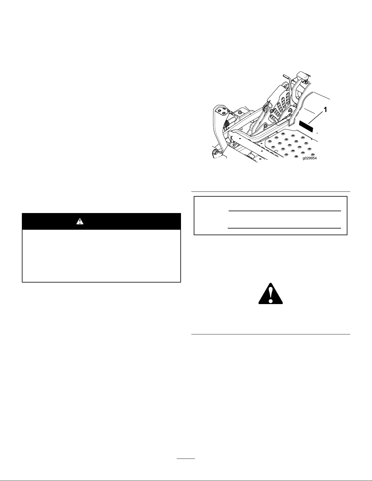
andserialnumbersofyourproductready.Figure1
identiesthelocationofthemodelandserialnumbers
ontheproduct.Writethenumbersinthespace
provided.
TheenclosedEngineOwner'sManualis
suppliedforinformationregardingtheUS
EnvironmentalProtectionAgency(EP A)and
theCaliforniaEmissionControlRegulationof
emissionsystems,maintenance,andwarranty.
Replacementsmaybeorderedthroughtheengine
manufacturer.
WARNING
CALIFORNIA
Proposition65Warning
Theengineexhaustfromthisproduct
containschemicalsknowntotheStateof
Californiatocausecancer,birthdefects,
orotherreproductiveharm.
Introduction
Thisrotary-blade,ridinglawnmowerisintendedtobe
usedbyresidentialhomeownersorprofessional,hired
operators.Itisdesignedprimarilyforcuttinggrasson
well-maintainedlawnsonresidentialorcommercial
properties.Itisnotdesignedforcuttingbrushorfor
agriculturaluses.
g029954
Figure1
1.Modelandserialnumberlocation
ModelNo.
SerialNo.
Thismanualidentiespotentialhazardsandhas
safetymessagesidentiedbythesafetyalertsymbol
(Figure2),whichsignalsahazardthatmaycause
seriousinjuryordeathifyoudonotfollowthe
recommendedprecautions.
g000502
Figure2
1.Safetyalertsymbol
Thismanualuses2wordstohighlightinformation.
Importantcallsattentiontospecialmechanical
informationandNoteemphasizesgeneralinformation
worthyofspecialattention.
Readthisinformationcarefullytolearnhowtooperate
andmaintainyourproductproperlyandtoavoid
injuryandproductdamage.Y ouareresponsiblefor
operatingtheproductproperlyandsafely .
YoumaycontactT orodirectlyatwww.T oro.com
forproductsafetyandoperationtrainingmaterials,
accessoryinformation,helpndingadealer,orto
registeryourproduct.
©2018—TheToro®Company
8111LyndaleAvenueSouth
Bloomington,MN55420
Contactusatwww.Toro.com.
2
PrintedintheUSA.
AllRightsReserved
Page 3

Contents
Safety.......................................................................4
SafeOperatingPractices....................................4
SlopeIndicator...................................................7
SafetyandInstructionalDecals..........................8
ProductOverview...................................................15
Controls...........................................................15
Specications..................................................16
Operation................................................................17
AddingFuel......................................................17
CheckingtheEngine-OilLevel..........................19
BreakinginaNewMachine..............................19
UsingtheRolloverProtectionSystem
(ROPS).........................................................19
EnteringtheUserPosition................................19
ThinkSafetyFirst..............................................20
OperatingtheParkingBrake.............................20
OperatingtheMowerBlade-ControlSwitch
(PTO)............................................................21
OperatingtheThrottle.......................................21
OperatingtheIgnitionSwitch............................21
UsingtheFuel-ShutoffValve.............................22
StartingandStoppingtheEngine......................22
TheSafety-InterlockSystem.............................23
DrivingForwardorBackward............................24
StoppingtheMachine.......................................25
AdjustingtheHeightofCut...............................25
AdjustingtheAnti-ScalpRollers........................27
AdjustingtheFlowBafeCamLocks................27
PositioningtheFlowBafe................................28
PositioningtheSeat..........................................29
UnlatchingtheSeat..........................................29
AdjustingtheMyRide™Suspension
System..........................................................29
UsingtheDriveWheelReleaseValves.............30
UsingtheSideDischarge.................................31
TransportingtheMachine.................................32
LoadingtheMachine........................................32
OperatingTips.................................................34
Maintenance...........................................................35
RecommendedMaintenanceSchedule(s)...........35
Lubrication..........................................................36
LubricatingtheMachine....................................36
GreasingtheMower.........................................36
LubricatetheCasterWheelHubs.....................38
EngineMaintenance...........................................39
ServicingtheAirCleaner..................................39
ServicingtheEngineOil....................................40
ServicingtheSparkPlugs.................................43
CheckSparkArrester(ifequipped)...................45
FuelSystemMaintenance...................................45
ServicingtheElectronicFuelInjection
System..........................................................45
ReplacingtheLow-PressureFuel
Filter..............................................................45
ServicingtheHigh-PressureFuelFilter.............46
ServicingtheFuelT ank.....................................46
ElectricalSystemMaintenance...........................46
ServicingtheBattery.........................................46
ServicingtheFuses..........................................48
Jump-StartingtheMachine...............................48
DriveSystemMaintenance..................................50
CheckingtheSeatBelt.....................................50
CheckingtheKnobsontheRollover
ProtectionSystem(ROPS)...........................50
AdjustingtheTracking......................................51
CheckingtheTirePressure...............................51
CheckingtheWheelLugNuts...........................52
CheckingtheWheelHubSlottedNut................52
AdjustingtheCasterPivotBearing....................52
UsingtheClutchShim......................................52
CoolingSystemMaintenance..............................54
CleaningtheEngineScreenandEngine-Oil
Cooler...........................................................54
CleaningtheEngineCoolingFinsand
Shrouds........................................................54
CheckandCleantheHydraulic-Unit
Shrouds........................................................55
BrakeMaintenance.............................................56
AdjustingtheParkingBrake..............................56
BeltMaintenance................................................57
InspectingtheBelts..........................................57
ReplacingtheMowerBelt.................................57
ReplacingtheHydraulicPumpDrive
Belt................................................................58
ControlsSystemMaintenance.............................59
AdjustingtheControlHandlePosition...............59
AdjustingtheMotion-ControlLinkage...............59
AdjustingtheMotion-ControlDamper...............60
AdjustingtheMotion-ControlNeutralLock
Pivot..............................................................60
HydraulicSystemMaintenance...........................61
ServicingtheHydraulicSystem........................61
MowerDeckMaintenance....................................63
LevelingtheMowerDeck..................................63
ServicingtheCuttingBlades.............................65
RemovingtheMowerDeck...............................68
ReplacingtheGrassDeector..........................69
Cleaning..............................................................70
CleaningundertheMower................................70
CleaningtheSuspensionSystem.....................70
DisposingofWaste...........................................70
Storage...................................................................71
CleaningandStorage.......................................71
Troubleshooting......................................................72
Schematics.............................................................75
3
Page 4

Safety
Improperlyusingormaintainingthemachinecan
resultininjury.T oreducethepotentialforinjury,
complywiththesesafetyinstructionsandalways
payattentiontothesafetyalertsymbol,which
meansCaution,Warning,orDanger—personal
safetyinstruction.Failuretocomplywiththe
instructionmayresultinpersonalinjuryordeath.
Thisproductiscapableofamputatinghandsand
feetandthrowingobjects.Alwaysfollowallsafety
instructionstoavoidseriousinjuryordeath.
Thisproductisdesignedforcuttingandrecycling
grassor,whenequippedwithagrassbagger,for
catchingcutgrass.Anyuseforpurposesother
thanthesecouldprovedangeroustotheuserand
bystanders.
SafeOperatingPractices
ThefollowinginstructionsareadaptedfromANSI
B71.4-2012.
Training
•ReadtheOperator'sManualandothertraining
material.Iftheoperator(s)ormechanic(s)cannot
readorunderstandtheinformationitistheowner's
responsibilitytoexplainthismaterialtothem.
•Becomefamiliarwiththesafeoperationofthe
equipment,operatorcontrols,andsafetysigns.
•Alloperatorsandmechanicsshouldbetrained.
Theownerisresponsiblefortrainingtheusers.
•Neverletchildrenoruntrainedpeopleoperateor
servicetheequipment.Localregulationsmay
restricttheageoftheoperator.
•Theowner/usercanpreventandisresponsible
foraccidentsorinjuriesoccurringtopeopleor
damagetoproperty.
Preparation
•Evaluatetheterraintodeterminewhataccessories
andattachmentsareneededtoproperlyand
safelyperformthejob.Onlyuseaccessoriesand
attachmentsapprovedbythemanufacturer.
•Wearappropriateclothingincludinghardhat,
safetyglasses,andhearingprotection.Long
hair,looseclothing,orjewelrymaygettangledin
movingparts.
•Inspecttheareawheretheequipmentistobe
usedandremoveallobjectssuchasrocks,toys,
andwirewhichcanbethrownbythemachine.
•Checkthatoperator'spresencecontrols,safety
switches,andshieldsareattachedandfunctioning
properly.Donotoperateunlesstheyare
functioningproperly.
Operation
•Lightningcancausesevereinjuryordeath.If
lightningisseenorthunderisheardinthearea,do
notoperatethemachine;seekshelter.
•Neverrunanengineinanenclosedarea.
•Onlyoperateingoodlight,keepingawayfrom
holesandhiddenhazards.
•Besurealldrivesareinneutralandparkingbrake
isengagedbeforestartingtheengine.Onlystart
theenginefromtheoperator'sposition.
•Besureofyourtractionwhileusingthismachine,
especiallywhenbackingup.Neveroperateonwet
grass.Reducedtractioncouldcauseslipping.
•Slowdownanduseextracareonhillsides.Be
suretotravelsidetosideonhillsides.Turf
conditionscanaffectthestabilityofthemachine.
Usecautionwhileoperatingneardrop-offs.
•Slowdownandusecautionwhenmakingturns
andwhenchangingdirectionsonslopes.
•Neverraisedeckwiththebladesrunning.
•NeveroperatewiththePTOshieldorotherguards
notsecurelyinplace.Besureallinterlocksare
attached,adjustedproperly,andfunctioning
properly.
•Neveroperatewiththedischargedeectorraised,
removedoraltered,unlessusingagrasscatcher.
•Donotchangetheenginegovernorsettingor
overspeedtheengine.
•Stoponlevelground,disengagedrives,engage
theparkingbrake(ifprovided),andshutoffthe
enginebeforeleavingtheoperator'spositionfor
anyreason,includingemptyingthecatchersor
uncloggingthechute.
•Stopequipmentandinspectbladesafterstriking
objectsorifanabnormalvibrationoccurs.Make
necessaryrepairsbeforeresumingoperations.
•Keephandsandfeetawayfromthecuttingunit.
•Lookbehindanddownbeforebackinguptobe
sureofaclearpath.
•Nevercarrypassengersonthemachine.
•Keeppetsandbystandersaway .
•Slowdownandusecautionwhenmakingturns
andcrossingroadsandsidewalks.Stopblades
ifnotmowing.
•Beawareofthemowerdischargedirectionand
donotpointitatanyone.
•Donotoperatethemowerundertheinuenceof
alcoholordrugs.
4
Page 5

•Usecarewhenloadingorunloadingthemachine
intoorfromatrailerortruck.
•Usecarewhenapproachingblindcorners,shrubs,
trees,orotherobjectsthatmayobscurevision.
RolloverProtectionSystem (ROPS)—UseandMaintenance
•TheROPSisanintegralandeffectivesafety
device.KeepafoldingROPSintheraised
andlockedpositionandusetheseatbeltwhen
operatingthemachine.
•LowerafoldingROPStemporarilyonlywhen
absolutelynecessary.Donotweartheseatbelt
whenfoldeddown.
•Beawarethereisnorolloverprotectionwhena
foldedROPSisinthedownposition.
•Becertainthattheseatbeltcanbereleased
quicklyintheeventofanemergency.
•Checktheareatobemowedandneverfolddown
afoldingROPSinareaswherethereareslopes,
dropoffsorwater.
•Checkcarefullyforoverheadclearances(i.e.
branches,doorways,electricalwires)before
drivingunderanyobjectsanddonotcontactthem.
•KeeptheROPSinsafeoperatingconditionby
periodicallythoroughlyinspectingfordamageand
keepingallmountingfastenerstight.
•ReplaceadamagedROPS.Donotrepairor
revise.
•DonotremovetheROPS.
•AnyalterationstoaROPSmustbeapprovedby
themanufacturer.
SafeHandlingofFuels
•Toavoidpersonalinjuryorpropertydamage,use
extremecareinhandlinggasoline.Gasolineis
extremelyammableandthevaporsareexplosive.
•Extinguishallcigarettes,cigars,pipes,andother
sourcesofignition.
•Useonlyanapprovedfuelcontainer.
•Neverremovefuelcaporaddfuelwiththeengine
running.
•Allowenginetocoolbeforerefueling.
•Neverrefuelthemachineindoors.
•Neverstorethemachineorfuelcontainerwhere
thereisanopename,spark,orpilotlightsuchas
onawaterheateroronotherappliances.
•Neverllcontainersinsideavehicleoronatruck
ortrailerbedwithaplasticliner.Alwaysplace
containersonthegroundawayfromyourvehicle
beforelling.
•Removeequipmentfromthetruckortrailerand
refuelitontheground.Ifthisisnotpossible,then
refuelsuchequipmentwithaportablecontainer,
ratherthanfromafueldispensernozzle.
•Keepthenozzleincontactwiththerimofthefuel
tankorcontaineropeningatalltimesuntilfueling
iscomplete.
•Donotuseanozzlelockopendevice.
•Iffuelisspilledonclothing,changeclothing
immediately.
•Neveroverllfueltank.Replacefuelcapand
tightensecurely.
MaintenanceandStorage
•Disengagedrives,settheparkingbrake,stop
theengineandremovethekeyordisconnect
thespark-plugwire.Waitforallmovementto
stopbeforeadjusting,cleaningorrepairingthe
machine.
•Cleangrassanddebrisfromthecuttingunit,the
drives,themufers,andtheenginetohelpprevent
res.Cleanupoilorfuelspillage.
•Lettheenginecoolbeforestoringanddonotstore
nearame.
•Shutoffthefuelwhilestoringortransporting.Do
notstorefuelnearamesordrainindoors.
•Parkthemachineonlevelground.Settheparking
brake.Neverallowuntrainedpersonneltoservice
themachine.
•Usejackstandstosupportcomponentswhen
required.
•Carefullyreleasepressurefromcomponentswith
storedenergy.
•Disconnectthebatteryorthespark-plugwire
beforemakinganyrepairs.Disconnectthe
negativeterminalrstandthepositivelast.
Connectthepositiverstandnegativelast.
•Usecarewhencheckingtheblades.Wrapthe
blade(s)orwearthickly-paddedgloves,anduse
cautionwhenservicingthem.Onlyreplaceblades.
Neverstraightenorweldthem.
•Keephandsandfeetawayfrommovingparts.If
possible,donotmakeadjustmentswiththeengine
running.
•Keepallpartsingoodworkingconditionandall
hardwaretightened.Replaceallwornordamaged
decals.
•Tobestprotectyourinvestmentandmaintain
optimalperformanceofyourToroequipment,count
onT orogenuineparts.Whenitcomestoreliability,
Torodeliversreplacementpartsdesignedtothe
exactengineeringspecicationsofourequipment.
Forpeaceofmind,insistonT orogenuineparts.
5
Page 6

Hauling
•Usecarewhenloadingorunloadingthemachine
intoatrailerortruck.
•Usefullwidthrampsforloadingthemachineintoa
trailerortruck.
•Tiethemachinedownsecurelyusingstraps,
chains,cable,orropes.Bothfrontandrearstraps
shouldbedirecteddownandoutwardfromthe
machine.
6
Page 7
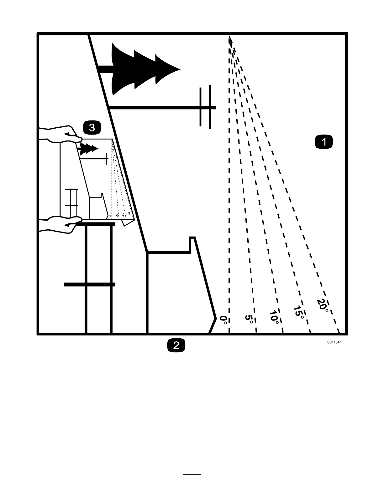
SlopeIndicator
Figure3
Thispagemaybecopiedforpersonaluse.
1.Themaximumslopeyoucansafelyoperatethemachineonis15degrees.Usetheslopecharttodeterminethedegreeofslope
ofhillsbeforeoperating.Donotoperatethismachineonaslopegreaterthan15degrees.Foldalongtheappropriateline
tomatchtherecommendedslope.
2.Alignthisedgewithaverticalsurface,atree,building,fencepole,etc.
3.Exampleofhowtocompareslopewithfoldededge.
7
g011841
Page 8
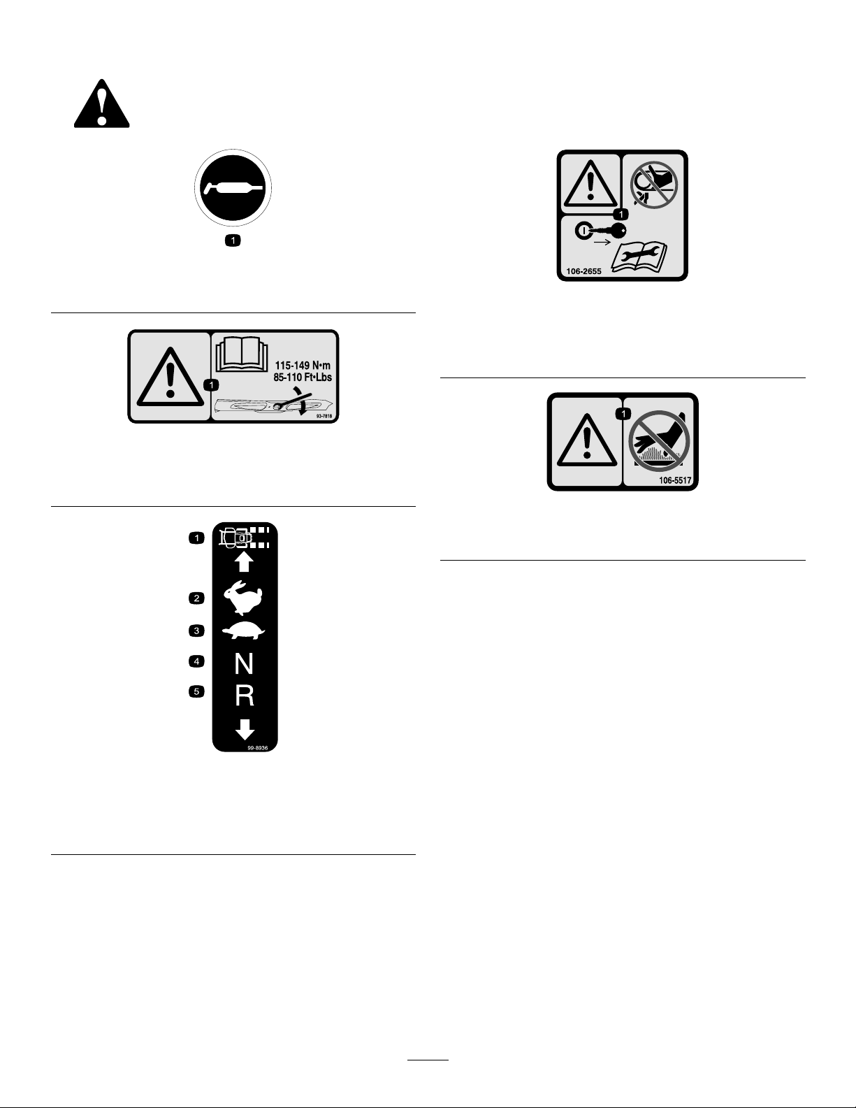
SafetyandInstructionalDecals
Safetydecalsandinstructionsareeasilyvisibletotheoperatorandarelocatednearanyarea
ofpotentialdanger.Replaceanydecalthatisdamagedorlost.
58-6520
1.Grease
93-7818
decal58-6520
decal106-2655
106-2655
1.Warning-donottouchorapproachmovingbelts;remove
theignitionkeyandreadtheinstructionsbeforeservicing
orperformingmaintenance.
decal93-7818
1.Warning—readtheOperator'sManualforinstructionson
torquingthebladebolt/nutto115-149N-m(85-110ft-lb).
99-8936
1.Machinespeed4.Neutral
2.Fast5.Reverse
3.Slow
decal106-5517
106-5517
1.Warning—donottouchthehotsurface.
decal99-8936
8
Page 9

decal107-3069
107-3069
1.Warning-thereisnorolloverprotectionwhentherollbaris
down.
2.Toavoidinjuryordeathfromarolloveraccident,keepthe
rollbarinthefullyraisedandlockedpositionandwear
theseatbelt.Lowertherollbaronlywhenabsolutely
necessary;donotweartheseatbeltwhentherollbaris
down.
3.ReadtheOperator’smanual;driveslowlyandcarefully.
decal110-2068
110-2068
1.ReadtheOperator'sManual.
decal112-9028
112-9028
1.Warning—stayawayfrommovingparts;keepallguardsin
place.
decal114-4466
114-4466
1.Main,25A
2.PTO,10A
3.Charge,25A
4.Auxiliary,15A
decal110-2067
110-2067
decal115-7445
115-7445
1.Greasepulleysandspindles
2.Maintenanceinterval—50hours
9
Page 10
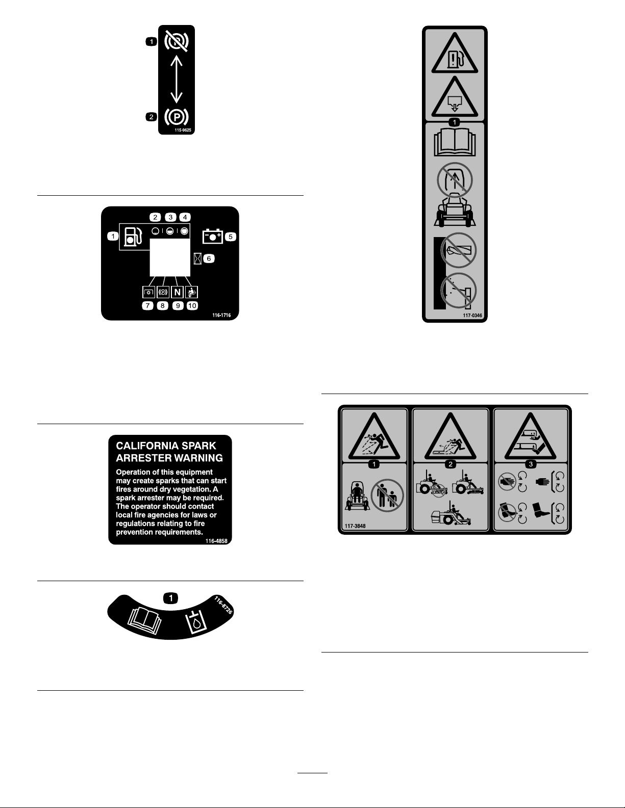
decal115-9625
115-9625
1.Parking
2.Parkingbrake—engaged
brake—disengaged
116-1716
1.Fuel6.Hourmeter
2.Empty
3.Half
4.Full9.Neutral
5.Battery
7.PTO
8.Parkingbrake
10.Operatorpresenceswitch
decal116-1716
decal117-0346
117-0346
1.Fuelleakhazard—readtheOperator'sManual;donot
attempttoremovetherollbar;donotweld,drillormodify
therollbarinanyway.
116-4858
116-8726
1.ReadtheOperator’sManualforrecommendedhydrooil.
decal116-4858
117-3848
decal117-3848
1.Thrownobjecthazard—keepbystandersasafedistance
fromthemachine
2.Thrownobjecthazard,mower-donotoperatewithoutthe
deector,dischargecoverorgrasscollectionsystemin
place.
3.Cutting/dismembermentofhandorfoot—stayawayfrom
movingparts;keepallguardsandshieldsinplace.
decal116-8726
10
Page 11
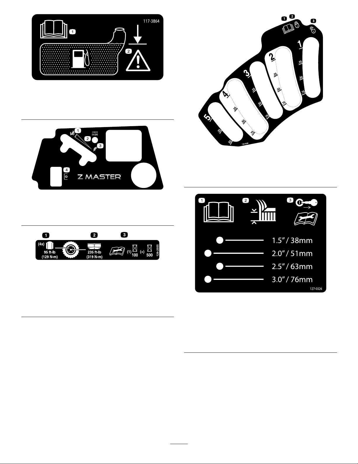
decal117-3864
117-3864
1.ReadtheOperator’s
Manual.
1.Fast
2.Variablespeedcontrol
2.Filltobottomofllerneck;
warning—donotoverll
thetank.
121–7586
3.Slow
4.Powertake-off(PTO)
126-2055
decal126-4398
126-4398
1.ReadtheOperator’s
manual
2.Lock
decal121-7586
decal126-2055
3.Unlock
1.Wheellugnuttorque95ft-lb(129N-m)(4x)
2.Wheelhubnuttorque235ft-lb(319N-m)
3.ReadandunderstandtheOperator’smanualbefore
performinganymaintenance,checktorqueafterrst100
hoursthenevery500hoursthereafter.
1.ReadtheOperator's
2.Height-of-cut
Manual.
decal127-0326
127-0326
3.Removethekeyfrom
theignitionandreadthe
Operator'sManualbefore
performingmaintenance
orservicingthemachine.
11
Page 12
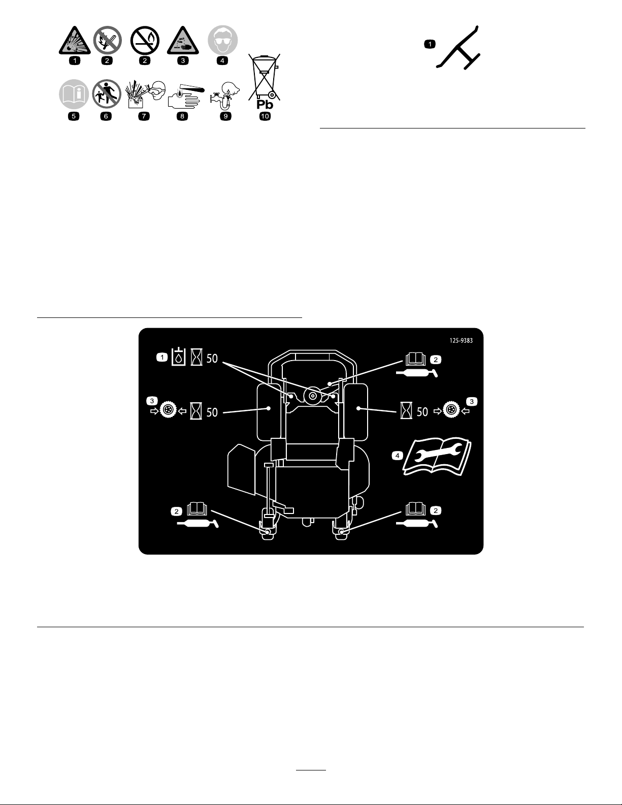
BatterySymbols
Someorallofthesesymbolsareonyourbattery
decaloemmarkt
Manufacturer'sMark
1.Indicatesthebladeisidentiedasapartfromtheoriginal
machinemanufacturer.
decalbatterysymbols
1.Explosionhazard
2.Nore,opename,or
6.Keepbystandersasafe
7.Weareyeprotection;
smoking.
3.Causticliquid/chemical
8.Batteryacidcancause
burnhazard
4.Weareyeprotection9.Flusheyesimmediately
5.ReadtheOperator's
10.Containslead;donot
Manual.
distancefromthebattery.
explosivegasescan
causeblindnessandother
injuries
blindnessorsevereburns.
withwaterandgetmedical
helpfast.
discard.
125–9383
1.Checkhydraulicoilevery50operatinghours.3.Checkthetirepressureevery50operatinghours.
2.ReadtheOperator’sManualforinformationonlubricating
themachine.
4.ReadtheOperator’sManualbeforeservicingorperforming
maintenance.
12
decal125-9383
Page 13

132-5063
1.Camlock2.Camunlock
decal132-5063
decal132-5067
132–5067
13
Page 14
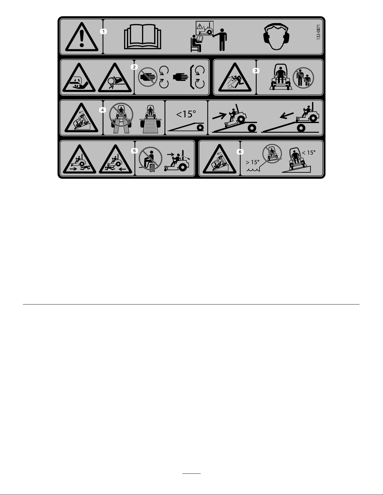
132-0871
Note:Thismachinecomplieswiththeindustrystandardstabilitytestinthestaticlateralandlongitudinaltestswiththemaximum
recommendedslopeindicatedonthedecal.ReviewtheinstructionsforoperatingthemachineonslopesintheOperator’sManualas
wellastheconditionsinwhichyouwouldoperatethemachinetodeterminewhetheryoucanoperatethemachineinthoseconditions
onthatdayandatthatsite.Changesintheterraincanresultinachangeinslopeoperationforthemachine.Ifpossible,keepthe
cuttingunitsloweredtothegroundwhileoperatingthemachineonslopes.Raisingthecuttingunitswhileoperatingonslopescan
causethemachinetobecomeunstable.
decal132-0871
1.Warning—readtheOperator’sManual;donotoperatethis
machineunlessyouaretrained;wearhearingprotection.
2.Cutting,dismembering,andentanglementhazard—keep
handsawayfrommovingparts;keepallguardsandshieldsin
place.
3.Thrownobjecthazard—keepbystandersaway.6.Tippinghazardonslopes—donotuseonslopesnearopen
4.Ramphazard—whenloadingontoatrailer ,donotusedual
ramps;onlyuseasingularrampwideenoughforthemachine
andthathasaninclinelessthan15°;backuptheramp(in
reverse)anddriveforwardofftheramp.
5.Bodilyharmhazard—donotcarrypassengers;lookbehind
youwhenmowinginreverse.
water;donotuseonslopesgreaterthan15°.
14
Page 15
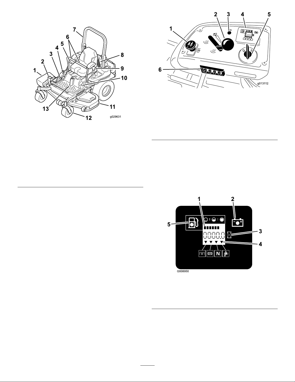
ProductOverview
g013112
Figure5
Figure4
1.Side-dischargedeector
2.Height-of-cutdeck-lift
pedal
3.Parking-brakelever10.Fuelcap
4.Transportlock11.Mowerdeck
5.Controls12.Casterwheel
6.Motion-controllevers13.Front,shockassembly
7.Rollbar
8.Rear,shockassembly
9.Seatbelt
Controls
Becomefamiliarwithallthecontrolsbeforeyoustart
theengineandoperatethemachine(Figure4and
Figure5).
1.PTOSwitch
g029631
2.Throttlecontrol5.Ignitionswitch
3.Malfunctionindicatorlight
(MIL)
4.Hour
meter/Safety-interlock
display/Fuelgauge
6.Fuses
FuelGauge
Thefuelgaugeislocatedwiththehourmeter,andthe
barslightupwhentheignitionswitchison(Figure6).
Theindicatorlightappearswhenthefuellevelis
low—approximately3.8L(1USgallon)remainingin
thefueltank.
Figure6
1.Fuelgauge(bars)4.Safety-interlocksymbols
2.Batterylight
3.Hourmeter
5.Low-fuelindicatorlight
HourMeter
Thehourmeterrecordsthenumberofhoursthe
enginehasoperated.Itoperateswhentheengine
isrunning.Usethesetimesforschedulingregular
maintenance(Figure5).
15
g008950
Page 16
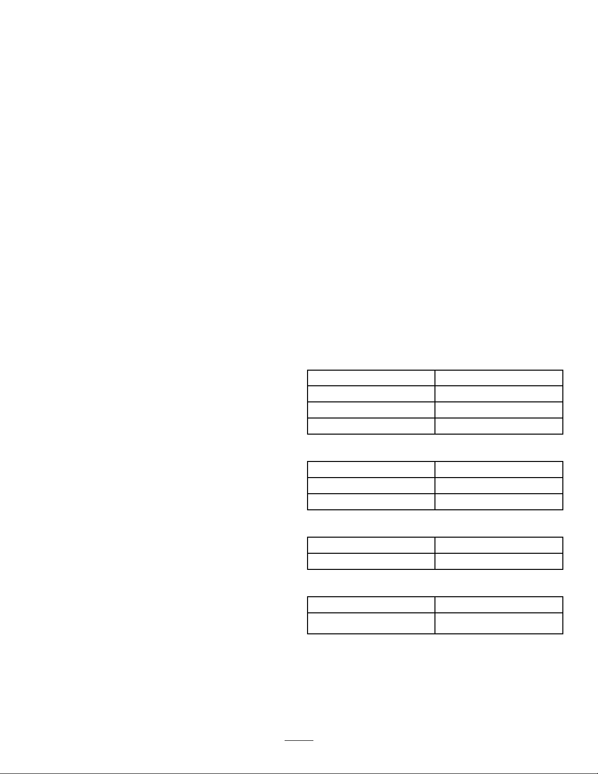
Safety-InterlockIndicators
Therearesymbolsonthehourmeterindicatewitha
blacktrianglethattheinterlockcomponentisinthe
correctposition(Figure6).
BatteryIndicatorLight
WhentheignitionkeyisinitiallyturnedtotheRun
positionforafewseconds,thebatteryvoltagewillbe
displayedintheareawherethehoursarenormally
displayed.
Thebatterylightturnsonwhentheignitionisturned
onandwhenthechargeisbelowthecorrectoperating
level(Figure6).
ThrottleControl
ThethrottlecontrolisvariablebetweenFastand
Slow.
Blade-ControlSwitch(PTO)
Theblade-controlswitch(PTO)isusedtoengage
theelectricclutchanddrivethemowerblades.Pull
theswitchuptoengagethebladesandrelease.T o
disengagetheblades,pushtheblade-controlswitch
(PTO)downormoveamotion-controlleverintothe
neutrallockposition.
IgnitionSwitch
Thisswitchisusedtostartthemowerengineandhas
threepositions:Start,RunandOff.
Motion-ControlLevers
Themotion-controlleversareusedtodrivethe
machineforward,reverse,andturneitherdirection.
Ifthesystemdetectsaproblemorfault,the
malfunctionindicatorlight(MIL)illuminates.
TheMIListheredlightlocatedintherightconsole
panel.
IftheMILilluminates,performtheinitial
troubleshootingchecks;refertotheMILsectionin
Troubleshooting(page72).
Ifthesechecksdonotcorrecttheproblem,further
diagnosisandservicingbyanAuthorizedService
Dealerisnecessary.
Attachments/Accessories
AselectionofT oroapprovedattachmentsand
accessoriesisavailableforusewiththemachineto
enhanceandexpanditscapabilities.Contactyour
AuthorizedServiceDealerorDistributororgoto
www.T oro.comforalistofallapprovedattachments
andaccessories.
Specications
Note:Specicationsanddesignaresubjectto
changewithoutnotice.
Width:
60-inchDeck
WithoutDeck
DeectorUp156.8cm(61.7inches)
DeectorDown192.2cm(75.7inches)
Length:
RollBar—Up
RollBar—Down
134.6cm(53.0inches)
60-inchDeck
211.1cm(83.1inches)
215.4cm(84.8inches)
Neutral-LockPosition
Theneutral-lockpositionisusedwiththe
safety-interlocksystemandtodeterminetheneutral
position.
Fuel-ShutoffValve
Closethefuel-shutoffvalve(undertheseat)when
transportingorstoringthemower.
ElectronicControlUnit
MalfunctionIndicatorLight
Theelectroniccontrolunit(ECU)continuously
monitorstheoperationoftheEFIsystem.
Height:
RollBar—UpRollBar—Down
179.1cm(70.5inches)118.9cm(46.8inches)
Weight:
ModelWeight
74991
16
587kg(1295lbs)
Page 17

Operation
Note:Determinetheleftandrightsidesofthe
machinefromthenormaloperatingposition.
AddingFuel
•Forbestresults,useonlyclean,fresh(lessthan
30daysold),unleadedgasolinewithanoctane
ratingof87orhigher((R+M)/2ratingmethod).
•Ethanol:Gasolinewithupto10%ethanol
(gasohol)or15%MTBE(methyltertiarybutyl
ether)byvolumeisacceptable.Ethanoland
MTBEarenotthesame.Gasolinewith15%
ethanol(E15)byvolumeisnotapprovedforuse.
Neverusegasolinethatcontainsmorethan10%
ethanolbyvolume,suchasE15(contains15%
ethanol),E20(contains20%ethanol),orE85
(containsupto85%ethanol).Usingunapproved
gasolinemaycauseperformanceproblemsand/or
enginedamagewhichmaynotbecoveredunder
warranty.
•Donotusegasolinecontainingmethanol.
•Donotstorefueleitherinthefueltankorfuel
containersoverthewinterunlessafuelstabilizer
isused.
•Donotaddoiltogasoline.
DANGER
Incertainconditions,gasolineisextremely
ammableandhighlyexplosive.Areor
explosionfromgasolinecanburnyouand
othersandcandamageproperty.
•Fillthefueltankoutdoors,inanopenarea,
whentheengineiscold.Wipeupany
gasolinethatspills.
•Neverllthefueltankinsideanenclosed
trailer.
•Donotllthefueltankcompletelyfull.Add
gasolinetothefueltankuntilthelevelis6
to13mm(1/4to1/2inch)belowthebottom
ofthellerneck.Thisemptyspaceinthe
tankallowsgasolinetoexpand.
•Neversmokewhenhandlinggasoline,and
stayawayfromanopenameorwhere
gasolinefumesmaybeignitedbyaspark.
•Storegasolineinanapprovedcontainer
andkeepitoutofthereachofchildren.
Neverbuymorethana30-daysupplyof
gasoline.
•Donotoperatewithouttheentireexhaust
systeminplaceandinproperworking
condition.
DANGER
Incertainconditionsduringfueling,static
electricitycancauseasparkwhichcanignite
thegasolinevapors.Areorexplosionfrom
gasolinecanburnyouandothersandcan
damageproperty.
•Alwaysplacegasolinecontainersonthe
groundawayfromyourvehiclebefore
lling.
•Donotllgasolinecontainersinsidea
vehicleoronatruckortrailerbed,because
interiorcarpetsorplastictruck-bedliners
mayinsulatethecontainerandslowthe
lossofanystaticcharge.
•Whenpractical,removegas-powered
equipmentfromthetruckortrailerand
fueltheequipmentwiththewheelsonthe
ground.
Ifthisisnotpossible,thenfuelsuch
equipmentonatruckortrailerfroma
portablecontainer,ratherthanfroma
gasoline-dispensernozzle.
•Ifagasolinedispensermustbeused,keep
thenozzleincontactwiththerimofthe
fueltankorcontaineropeningatalltimes
untilfuelingiscomplete.
WARNING
Gasolineisharmfulorfatalifswallowed.
Long-termexposuretovaporscancause
seriousinjuryandillness.
•Avoidprolongedbreathingofvapors.
•Keepfaceawayfromnozzleandgastank
orconditionerbottleopening.
•Avoidcontactwithskin;washoffspillage
withsoapandwater.
UsingFuelStabilizer/Conditioner
Useafuelstabilizer/conditionerinthemachineto
keepthefuelfreshduringstorageof90daysorless.
Ifyouarestoringthemachineforlonger,drainthefuel
tank;refertoStorage(page71).
Important:Donotusefueladditivescontaining
methanolorethanol.
Addthecorrectamountoffuelstabilizer/conditionerto
thefuel,andfollowthedirectionsofthemanufacturer.
Note:Fuelstabilizer/conditionerismosteffective
whenmixedwithfreshgasoline.T ominimizethe
17
Page 18
chanceofvarnishdepositsinthefuelsystem,usefuel
stabilizeratalltimes.
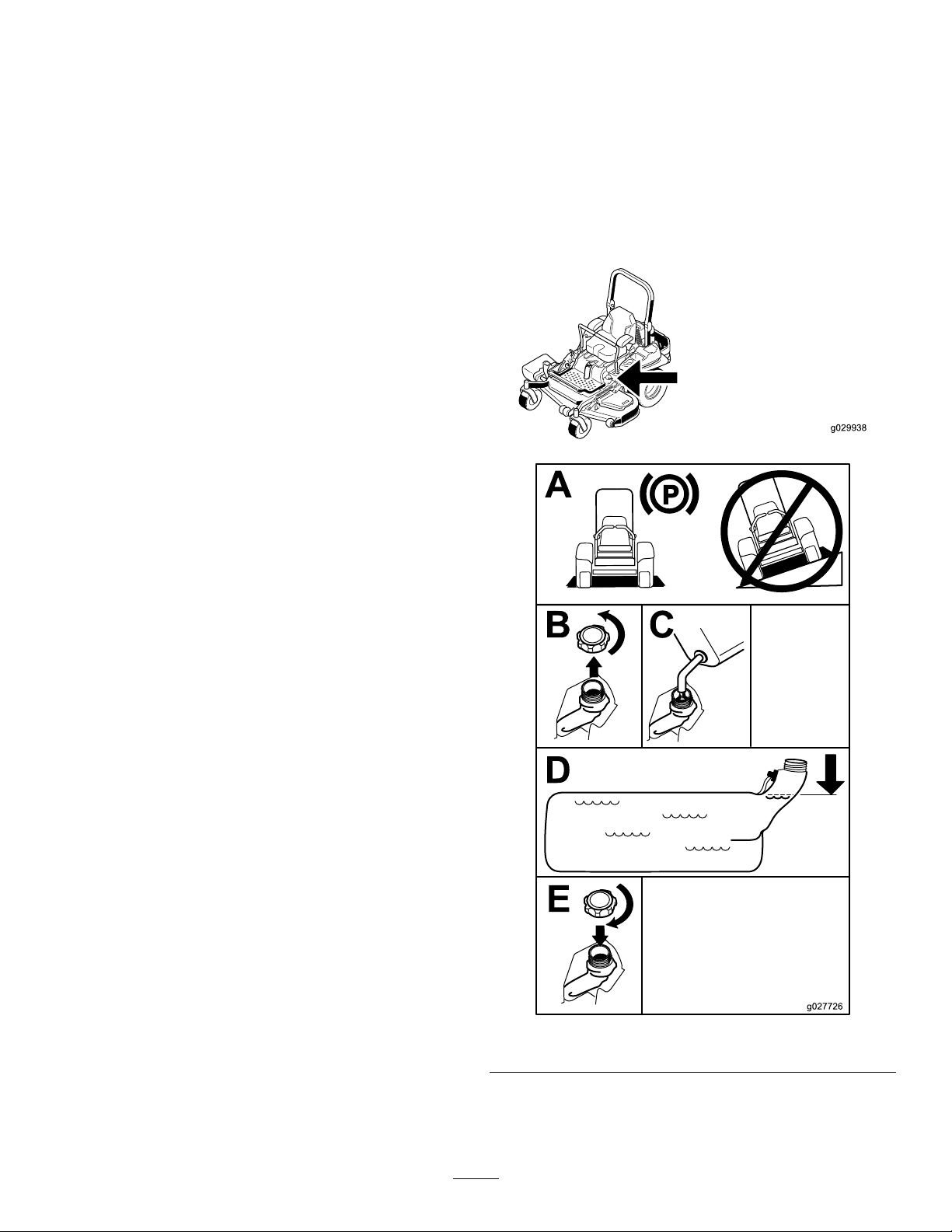
FillingtheFuelTank
1.Parkthemachineonlevelground.
2.Shuttheengineoffandsettheparkingbrake.
3.Cleanaroundthefuel-tankcapandremoveit.
Addregularunleadedgasolinetothefueltank
untilthelevelis6to13mm(1/4to1/2inch)
belowthebottomofthellerneck.Thisextra
spaceinthetankallowsthegasolinetoexpand.
Donotllthefueltankcompletelyfull;referto
(Figure7).
g029938
g027726
Figure7
18
Page 19
CheckingtheEngine-Oil Level
Beforeyoustarttheengineandusethemachine,
checktheoillevelintheenginecrankcase;referto
CheckingtheEngine-OilLevel(page40).
BreakinginaNewMachine
Newenginestaketimetodevelopfullpower.Mower
decksanddrivesystemshavehigherfrictionwhen
new,placingadditionalloadontheengine.Allow
40to50hoursofbreak-intimefornewmachinesto
developfullpowerandbestperformance.
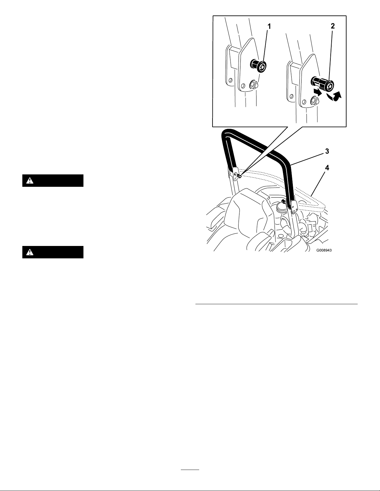
UsingtheRollover ProtectionSystem(ROPS)
WARNING
Toavoidinjuryordeathfromrollover:keep
therollbarinthefullyraisedlockedposition
andusetheseatbelt.
Ensurethattherearpartoftheseatissecured
withtheseatlatch.
WARNING
Thereisnorolloverprotectionwhentheroll
barisinthedownposition.
•Lowertherollbaronlywhenabsolutely
necessary.
•Donotweartheseatbeltwhentherollbar
isinthedownposition.
•Driveslowlyandcarefully.
•Raisetherollbarassoonasclearance
permits.
•Checkcarefullyforoverheadclearances
(i.e.branches,doorways,electricalwires)
beforedrivingunderanyobjectsanddo
notcontactthem.
Important:Lowertherollbaronlywhen
absolutelynecessary.
Figure8
1.ROPSknob
2.PullROPSknoboutand
rotate90degrees
4.Toraisetherollbar,raisetherollbartothe
operateposition,rotatetheknobssothatthey
movepartiallyintothegrooves(Figure8).
5.Raisetherollbartothefulluprightpositionwhile
pushingontheupperrollbarandthepinswill
snapintopositionwhentheholesalignwiththe
pins(Figure8).Pushontherollbarandensure
thatbothpinsareengaged.
3.Rollbarintheupright
position
4.Rollbarinthefolded
position
Important:Alwaysusetheseatbeltwiththe
rollbarinthefullyraisedposition.
g008943
1.Tolowertherollbar,applyforwardpressureto
theupperpartoftherollbar.
2.Pullbothknobsoutandrotatethem90°sothat
theyarenotengaged(Figure8).
3.Lowertherollbartothedownposition(Figure
8).
EnteringtheUserPosition
Usethemowerdeckasasteptogetintotheuser
position(Figure9).
19
Page 20
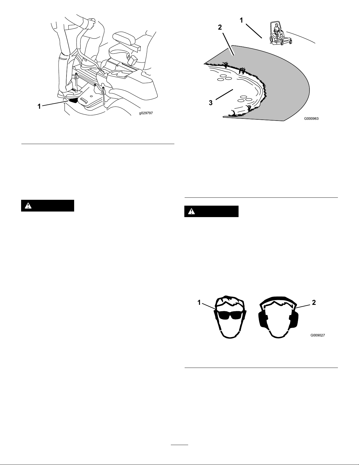
Figure9
1.Mowerdeck
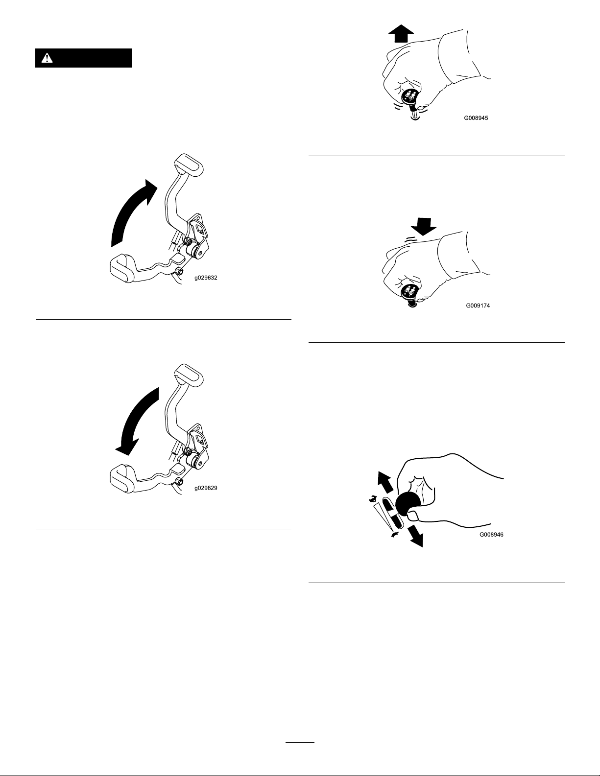
ThinkSafetyFirst
Pleasereadallsafetyinstructionsandsymbolsinthe
safetysection.Knowingthisinformationcouldhelp
youorbystandersavoidinjury.
g029797
Figure10
1.SafeZone-usethe
ZMasterhereonslopes
lessthan15degreesor
atareas.
2.DangerZone-useawalk
behindmowerand/ora
handtrimmeronslopes
greaterthan15degrees,
neardrop-offsandwater.
3.Water
g000963
DANGER
Operatingonwetgrassorsteepslopescan
causeslidingandlossofcontrol.
Wheelsdroppingoveredgescancause
rollovers,whichmayresultinseriousinjury,
death,ordrowning.
Thereisnorolloverprotectionwhentheroll
barisdown.
Alwayskeeptherollbarinthefullyraisedand
lockedpositionandusetheseatbelt.
Readandfollowtherolloverprotection
instructionsandwarnings.
Toavoidlossofcontrolandpossibilityof
rollover:
•Donotoperateneardrop-offsornear
water.
•Donotoperateonslopesgreaterthan
15degrees.
CAUTION
Thismachineproducessoundlevelsin
excessof85dBAattheoperator’searand
cancausehearinglossthroughextended
periodsofexposure.
Wearhearingprotectionwhenoperatingthis
machine.
Theuseofprotectiveequipmentforeyes,ears,feet,
andheadisrecommended.
Figure11
1.Wearsafetyglasses
2.Wearhearingprotection
g009027
•Reducespeedanduseextremecautionon
slopes.
•Avoidsuddenturnsorrapidspeed
changes.
OperatingtheParking Brake
Alwayssettheparkingbrakewhenyoustopthe
machineorleaveitunattended.
20
Page 21
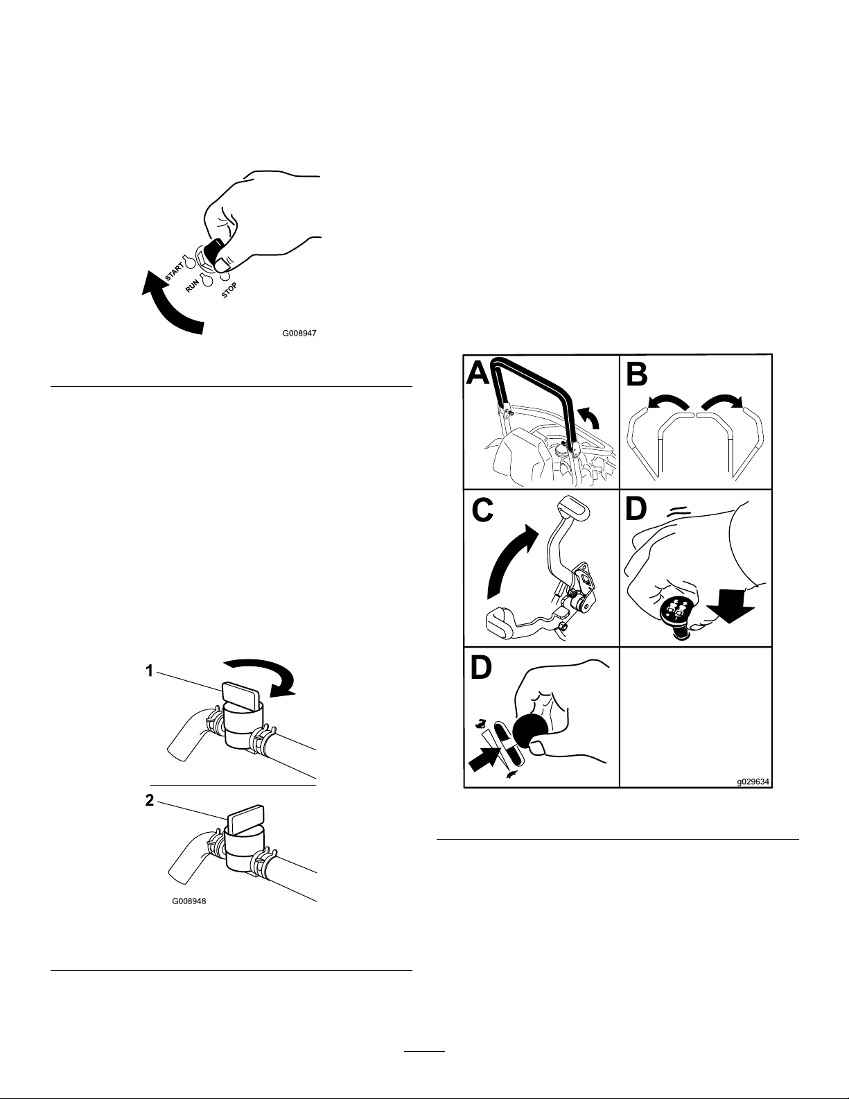
SettingtheParkingBrake
WARNING
Theparkingbrakemaynotholdmachine
parkedonaslopeandcouldcausepersonal
injuryorpropertydamage.
Donotparkonslopesunlessthewheelsare
chockedorblocked.
Figure12
ReleasingtheParkingBrake
g008945
Figure14
DisengagingtheBlade-Control Switch(PTO)
g029632
g009174
Figure15
OperatingtheThrottle
ThethrottlecontrolcanbemovedbetweenFastand
Slowpositions(Figure16).
Figure13
OperatingtheMower Blade-ControlSwitch(PTO)
Theblade-controlswitch(PTO)startsandstopsthe
mowerbladesandanypoweredattachments.
EngagingtheBlade-Control Switch(PTO)
Note:Engagingtheblade-controlswitch(PTO)with
thethrottlepositionathalforlesswillcauseexcessive
weartothedrivebelts.
Alwaysusethefastpositionwhenturningonthe
mowerdeckwiththeblade-controlswitch(PTO).
g029829
g008946
Figure16
OperatingtheIgnition Switch
1.TurntheignitionkeytotheStartposition(Figure
17).Whentheenginestarts,releasethekey.
Important:Donotengagethestarterfor
morethan5secondsatatime.Iftheengine
failstostart,allowa15secondcool-down
21
Page 22
periodbetweenattempts.Failuretofollow
theseinstructionscanburnoutthestarter
motor.
Note:Additionalstartingcyclesmaybe
requiredwhenstartingtheenginefortherst
timeafterthefuelsystemhasbeencompletely
withoutfuel.
Figure17
2.Tostoptheengine,turntheignitionkeytothe
stopposition.
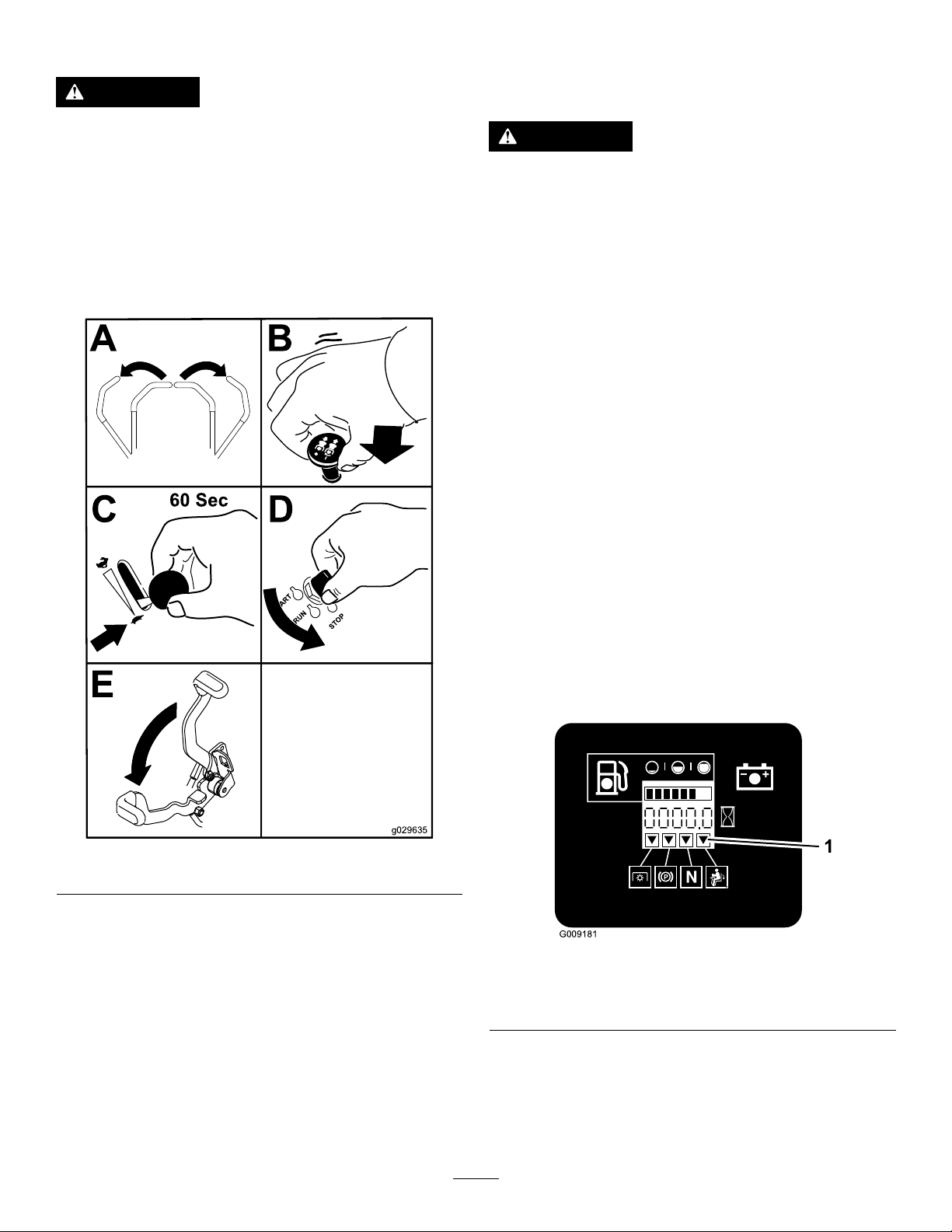
StartingandStoppingthe Engine
StartingtheEngine
1.RaisetheROPSupandlockintoplace,siton
theseatandfastentheseatbelt.
2.Movethemotioncontrolstoneutral-locked
position.
3.Settheparkingbrake;refertoSettingthe
ParkingBrake.
4.Movetheblade-controlswitch(PTO)totheOff
position(Figure19).
5.Movethethrottlelevermidwaybetweenthe
g008947
SlowandFastpositions.
UsingtheFuel-Shutoff Valve
Thefuel-shutoffvalveislocatedundertheseat.Move
theseatforwardtoaccessit.
Closethefuel-shutoffvalvefortransport,maintenance,
andstorage.
Ensurethatthefuel-shutoffvalveisopenwhen
startingtheengine.
g029634
Figure19
6.TurntheignitionkeytotheStartposition(Figure
17).Whentheenginestarts,releasethekey.
Figure18
1.On2.Off
g008948
22
Page 23
StoppingtheEngine
TheSafety-Interlock
CAUTION
Childrenorbystandersmaybeinjuredifthey
moveorattempttooperatethemachinewhile
itisunattended.
Alwaysremovetheignitionkeyandsetthe
parkingbrakewhenleavingthemachine
unattended,evenifjustforafewminutes.
Lettheengineidleatslowthrottle(turtle)for60
secondsbeforeturningtheignitionswitchoff.
System
CAUTION
Ifsafety-interlockswitchesaredisconnected
ordamagedthemachinecouldoperate
unexpectedlycausingpersonalinjury.
•Donottamperwiththeinterlockswitches.
•Checktheoperationoftheinterlock
switchesdailyandreplaceanydamaged
switchesbeforeoperatingthemachine.
Understandingthe Safety-InterlockSystem
Thesafety-interlocksystemisdesignedtopreventthe
enginefromstartingunless:
•Theparkingbrakeisengaged.
•Theblade-controlswitch(PTO)isdisengaged.
•Themotion-controlleversareintheneutral-locked
position
Figure20
Important:Makesurethatthefuelshutoff
valveisclosedbeforetransportingorstoring
themachine,asfuelleakagemayoccur.Setthe
parkingbrakebeforetransporting.Makesureto
removethekeyasthefuelpumpmayrunand
causethebatterytolosecharge.
Thesafety-interlocksystemalsoisdesignedtostop
theenginewhenthetractioncontrolsaremovedfrom
thelockedpositionwiththeparkingbrakeengagedor
ifyourisefromtheseatwhenthePTOisengaged.
Thehourmeterhassymbolstonotifytheuserwhen
theinterlockcomponentisinthecorrectposition.
Whenthecomponentisinthecorrectposition,a
trianglewilllightupinthecorrespondingsquare.
g029635
g009181
Figure21
1.Triangleslightupwhentheinterlockcomponentsareinthe
correctposition
TestingtheSafety-Interlock System
ServiceInterval:Beforeeachuseordaily
23
Page 24
Testthesafety-interlocksystembeforeyouusethe
machineeachtime.Ifthesafetysystemdoesnot
operateasdescribedbelow,haveanAuthorized
ServiceDealerrepairthesafetysystemimmediately .
1.Sittingontheseat,engagetheparkingbrake
andmovetheblade-controlswitch(PTO)toon.
Trystartingtheengine;theengineshouldnot
crank.
2.Sittingontheseat,engagetheparkingbrake
andmovetheblade-controlswitch(PTO)to
off.Moveeithermotion-controllever(outof
neutral-lockedposition).Trystartingtheengine;
theengineshouldnotcrank.Repeatforother
controllever.
3.Sittingontheseat,engagetheparkingbrake,
movetheblade-controlswitch(PTO)tooffand
movethemotion-controlleverstoneutrallock
position.Nowstarttheengine.Whiletheengine
isrunning,releasetheparkingbrake,engage
theblade-controlswitch(PTO)andriseslightly
fromtheseat;theengineshouldstop.
4.Sittingontheseat,engagetheparkingbrake,
movetheblade-controlswitch(PTO)tooffand
movethemotion-controlleverstoneutrallock
position.Nowstarttheengine.Whiletheengine
isrunning,centereithermotioncontroland
move(forwardorreverse);theengineshould
stop.Repeatforothermotioncontrol.
5.Sittingontheseat,disengagetheparkingbrake,
movetheblade-controlswitch(PTO)tooffand
movethemotion-controlleverstoneutrallock
position.Trystartingtheengine;theengine
shouldnotcrank.
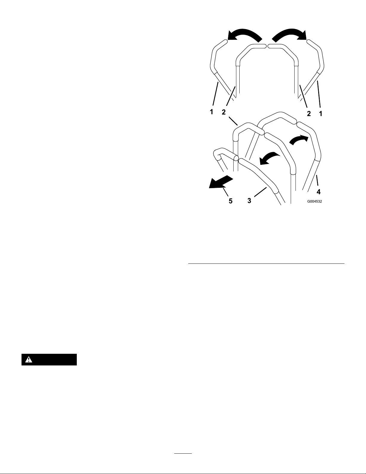
UsingtheMotion-ControlLevers
Figure22
1.motion-control
lever—neutral-lock
position
2.Center,unlockedposition5.Frontofmachine
3.Forward
g004532
4.Backward
DrivingForwardor Backward
Thethrottlecontrolregulatestheenginespeedas
measuredinrpm(revolutionsperminute).Place
thethrottlecontrolinthefastpositionforbest
performance.Alwaysoperateinthefullthrottle
positionwhenmowing.
CAUTION
Machinecanspinveryrapidly.Operatormay
losecontrolofmachineandcausepersonal
injuryordamagetomachine.
•Usecautionwhenmakingturns.
•Slowthemachinedownbeforemaking
sharpturns.
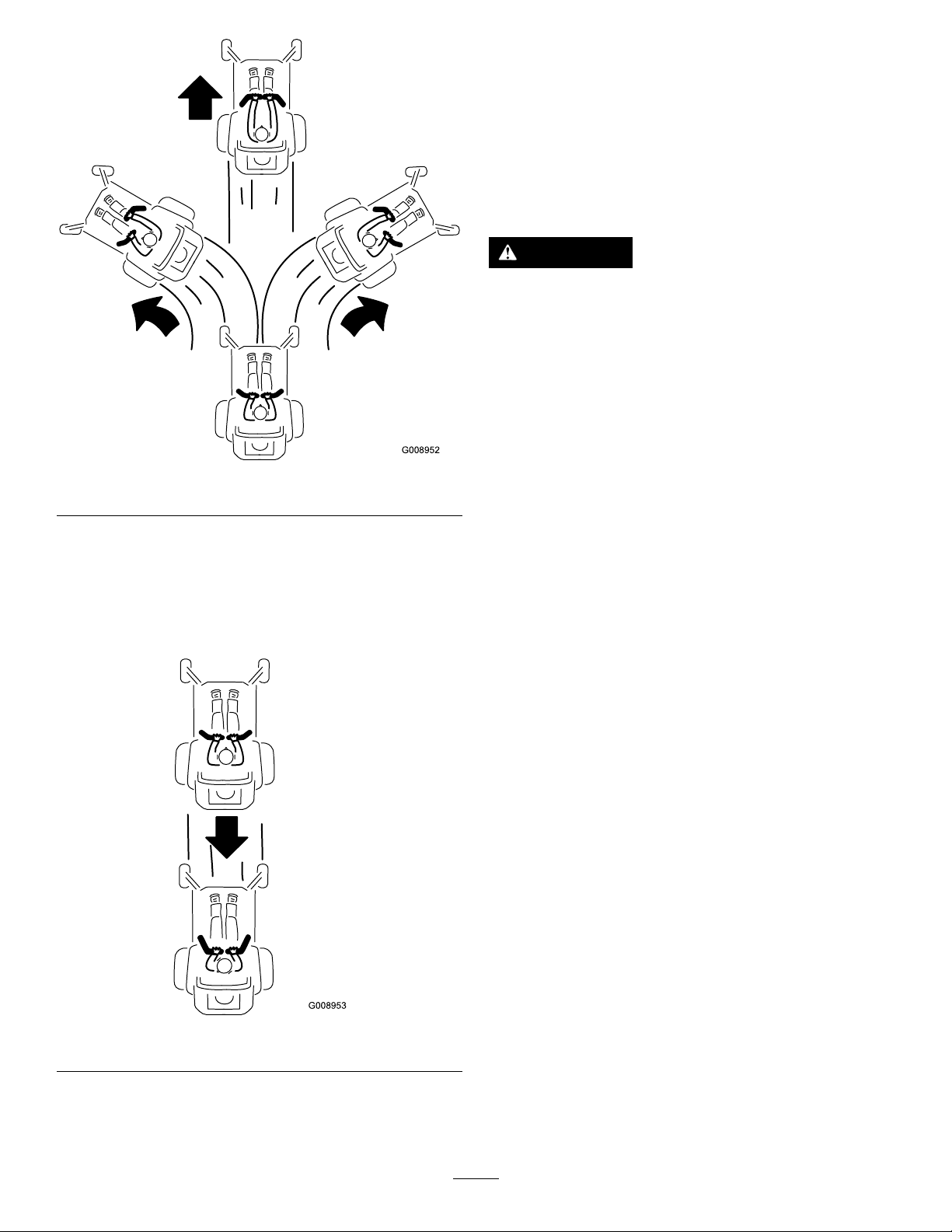
DrivingForward
Note:Theenginewillkillifthetractioncontrollevers
aremovedwiththeparkingbrakeengaged.
Tostop,pullthemotion-controlleverstotheneutral
position.
1.Releasetheparkingbrake;refertoReleasing
theParkingBrakeinOperation.
2.Movetheleverstothecenter,unlockedposition.
3.Togoforward,slowlypushthemotion-control
leversforward(Figure23).
24
Page 25
StoppingtheMachine
Tostopthemachine,movethetractioncontrollevers
toneutralandtothelockedposition,disengagethe
powertake-off(blade-controlswitch(PTO),andturn
theignitionkeytooff.
Settheparkingbrakewhenyouleavethemachine;
refertoSettingtheParkingBrakeinOperation.
Remembertoremovethekeyfromtheignitionswitch.
CAUTION
Childrenorbystandersmaybeinjuredifthey
moveorattempttooperatethemachinewhile
itisunattended.
Alwaysremovetheignitionkeyandsetthe
parkingbrakewhenleavingthemachine
unattended,evenifjustforafewminutes.
Figure23
DrivingBackward
1.Movetheleverstothecenter,unlockedposition.
2.Togobackward,lookbehindandslowlypullthe
motion-controlleversrearward(Figure24).
g008952
AdjustingtheHeightofCut
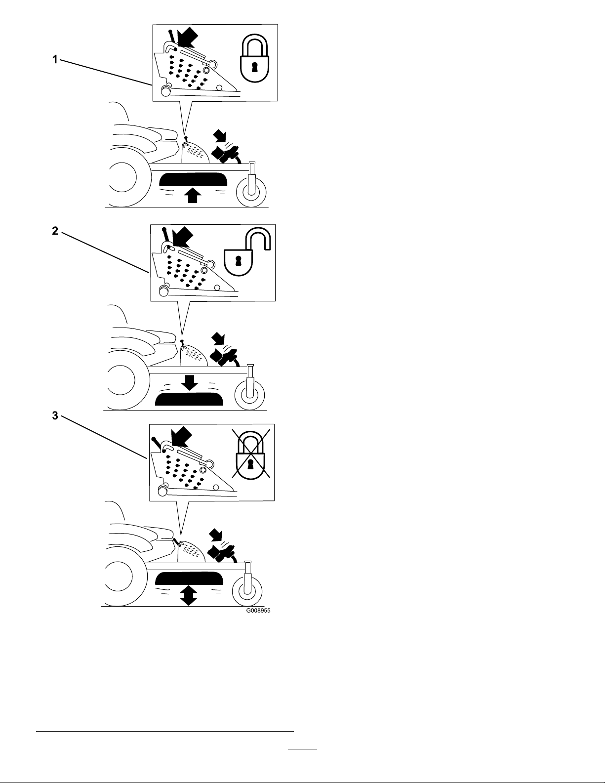
UsingtheTransportLock
Thetransportlockhas2positionsandisusedwiththe
deckliftpedal.Thereisalockpositionandanunlock
positionforthetransportposition.Thetransportlock
isusedwiththedeckliftpedal.RefertoFigure25
Figure24
g008953
25
Page 26
AdjustingtheHeight-of-CutPin
Theheightofcutisadjustedfrom25to140mm(1to
5-1/2inches)in6mm(1/4inch)incrementsbymoving
theclevispinintodifferentholelocations.
1.Movethetransportlocktothelockposition.
2.Pushonthedeckliftpedalwithyourfoot,and
raisethemowerdecktothetransportposition
(alsothe140mm(5-1/2inch)cutting-height
position);refertoFigure26.
3.Toadjust,rotatethepin90degreesandremove
thepinfromtheheight-of-cutbracket(Figure
26).
4.Selectaholeintheheight-of-cutbracket
correspondingtotheheightofcutdesired,and
insertthepin(Figure26).
5.Pushonthedecklift,pullbackonthetransport
lock,andslowlylowerthemowerdeck.
Figure25
Transportlockpositions
1.Transportlock3.Unlockposition—doesnot
lockthemowerdeckinto
transportposition
2.Lockposition—mower
deckwilllockintotransport
position
g008955
26
Page 27
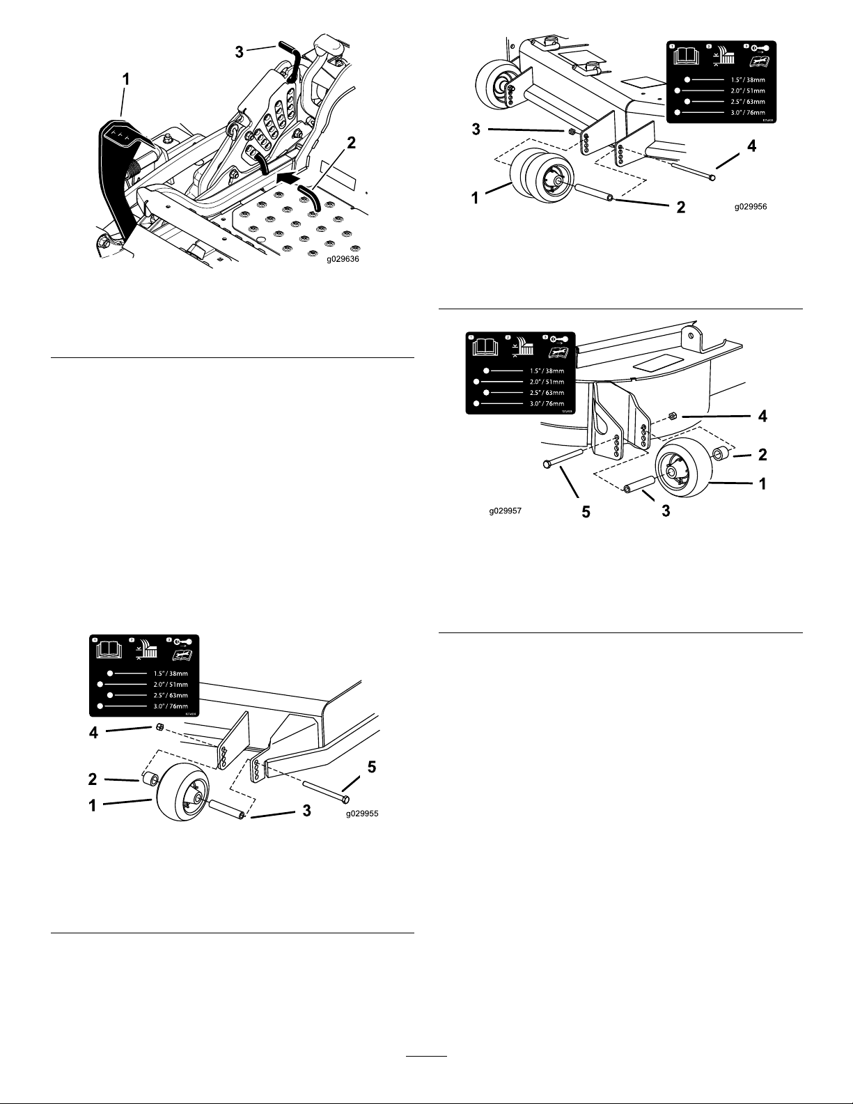
Figure28
g029956
Figure26
1.Deckliftpedal
2.Height-of-cutpin
3.Transportlock
AdjustingtheAnti-Scalp Rollers
Wheneveryouchangetheheightofcut,itis
recommendedtoadjusttheheightoftheanti-scalp
rollers.
1.Disengagetheblade-controlswitch(PTO),move
themotion-controlleverstotheneutral-locked
position,andsettheparkingbrake.
2.Stoptheengine,removethekey ,andwait
forallmovingpartstostopbeforeleavingthe
operatingposition.
g029840
1.Anti-scalproller3.Flangenut
2.Bushing4.Bolt
Figure29
1.Anti-scalproller4.Flangenut
2.Spacer
3.Bushing
5.Bolt
g029957
Figure27
1.Anti-scalproller4.Flangenut
2.Spacer
3.Bushing
5.Bolt
AdjustingtheFlowBafe
CamLocks
Thisprocedureisapplicableonlytomachineswith
theowbafelocks.Certainmodelswillhavenuts
andboltsin-placeoftheowbafelocksandcanbe
adjustedthesame.
g029955
Themowerdischargeowcanbeadjustedfor
differenttypesofmowingconditions.Positionthecam
locksandbafetogivethebestqualityofcut.
1.Disengagetheblade-controlswitch(PTO),move
themotion-controlleverstotheneutral-locked
positionandsettheparkingbrake.
2.Stoptheengine,removethekey ,andwait
forallmovingpartstostopbeforeleavingthe
operatingposition.
3.Toadjustthecamlocks,swingtheleverupto
loosenthecamlock(Figure30).
27
Page 28
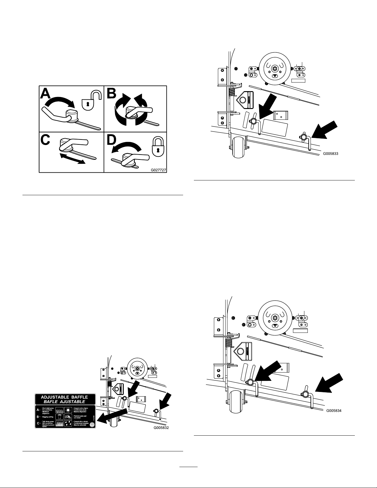
4.Adjustthebafeandcamlocksintheslotsto
thedesireddischargeow.
5.Swingtheleverbackovertotightenthebafe
andcamlocks(Figure30).
6.Ifthecamlocksdonotlockthebafeintoplace
oritistootight,loosentheleverandthenrotate
thecamlock.Adjustthecamlockuntilthe
desiredlockingpressureisachieved.
Figure30
PositionB
Usethispositionwhenbagging.Alwaysalignitwith
thebloweropening.
g005833
Figure32
g027727
PositioningtheFlowBafe
Thefollowingguresareonlyrecommendationsfor
use.Adjustmentswillvarybygrasstype,moisture
content,andheightofgrass.
Note:Iftheenginepowerdrawsdownandthe
mowergroundspeedisthesame,openupthebafe.
PositionA
Thisisthefullrearposition.Thesuggestedusefor
thispositionisasfollows.
•Useforshort,lightgrass-mowingconditions.
•Useindryconditions.
•Forsmallergrassclippings.
•Propelsgrassclippingsfartherawayfromthe
mower.
PositionC
Thisisthefullopenposition.Thesuggestedusefor
thispositionisasfollows.
•Useintall,densegrass-mowingconditions.
•Useinwetconditions.
•Lowerstheenginepowerconsumption.
•Allowsincreasedgroundspeedinheavy
conditions.
•ThispositionissimilartothebenetsoftheToro
SFSmower.
Figure31
g005834
Figure33
g005832
28
Page 29
PositioningtheSeat
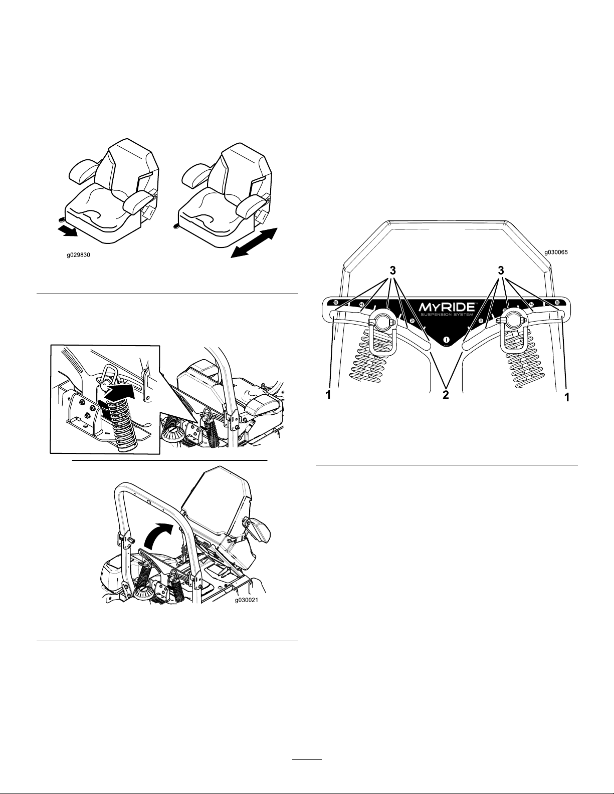
Theseatcanmoveforwardandbackward.Position
theseatwhereyouhavethebestcontrolofthe
machineandaremostcomfortable.
2shockassembliesistheeasiestandquickest
adjustmentforchangingthesuspensionsystem.
Positionthesuspensionsystemwhereyouaremost
comfortable.
Toadjusttheseat,movetheleversidewaystounlock
seatandthenmovetheseatforwardorbackward
(Figure34).
Figure34
UnlatchingtheSeat
AdjustingtheRear,Shock Assemblies
Theslotsfortherear,shockassemblieshavedetent
positionsforreference.Therear,shockassemblies
canbepositionedanywhereintheslot,notjustthe
detentpositions.
Thefollowinggraphicshowsthepositionforasoftor
rmrideandthedifferentdetentpositions(Figure36).
g029830
AdjustingtheMyRide™
g030065
Figure36
1.Firmestposition3.Detentsintheslots
2.Softestposition
Note:Ensuretheleftandrightrear,shockassemblies
arealwaysadjustedtothesamepositions.
g030021
Figure35
SuspensionSystem
TheMyRide™suspensionsystemadjuststoprovide
asmoothandcomfortableride.Adjustingtherear
29
Page 30
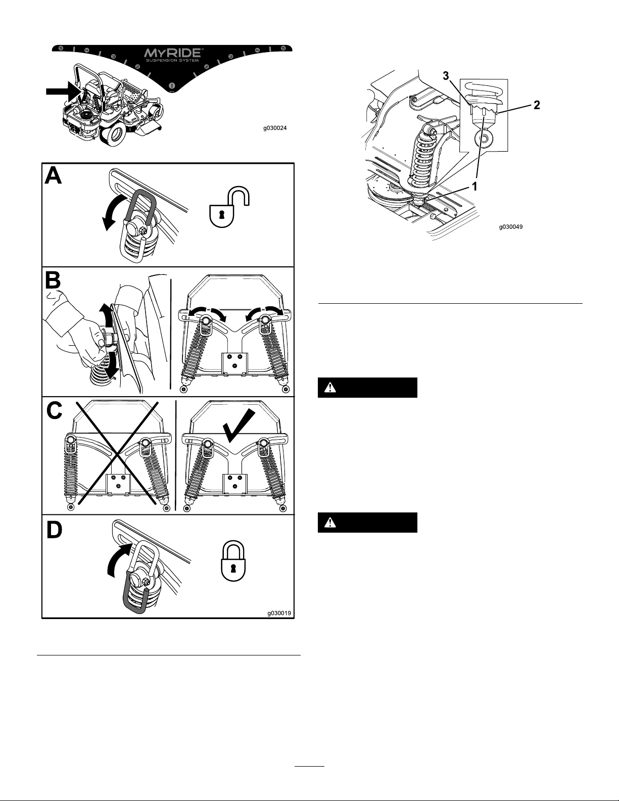
Adjusttherear,shockassemblies(Figure37).
Toadjustthefront,shockassembly ,opentheoor
panandadjustitbyusingaspannerwrench(Toro
partno.132–5069)oraslip-jointpliers(Figure38).
g030024
g030049
Figure38
1.Middleposition
2.Firmride
3.Softride
UsingtheDriveWheel ReleaseValves
WARNING
Handsmaybecomeentangledintherotating
drivecomponentsbelowtheenginedeck,
whichcouldresultinseriousinjury.
Stoptheengine,removethekey,andallow
allmovingpartstostopbeforeaccessingthe
drivewheelreleasevalves.
WARNING
Theengineandhydraulicdriveunitscan
becomeveryhot.Touchingahotengineor
hydraulicdriveunitscancausesevereburns.
Figure37
AdjustingtheFront,Shock Assembly
Thefront,shockassemblyissetatthemiddleposition
andisnormallynotadjusted.
Allowtheengineandhydraulicdriveunitsto
coolcompletelybeforeaccessingthedrive
g030019
wheelreleasevalves.
Thedrivewheelreleasevalvesarelocatedintheback
ofeachhydraulicdriveunit,undertheseat.
Note:Makesurethereleasevalvesareinthefully
horizontalpositionwhenoperatingthemachineor
severedamagetothehydraulicsystemcanoccur.
1.DisengagethePTO(blade-controlswitch)and
turntheignitionkeytooff.Movetheleversto
30
Page 31
neutral-lockedpositionandapplyparkingbrake.
Removethekey.
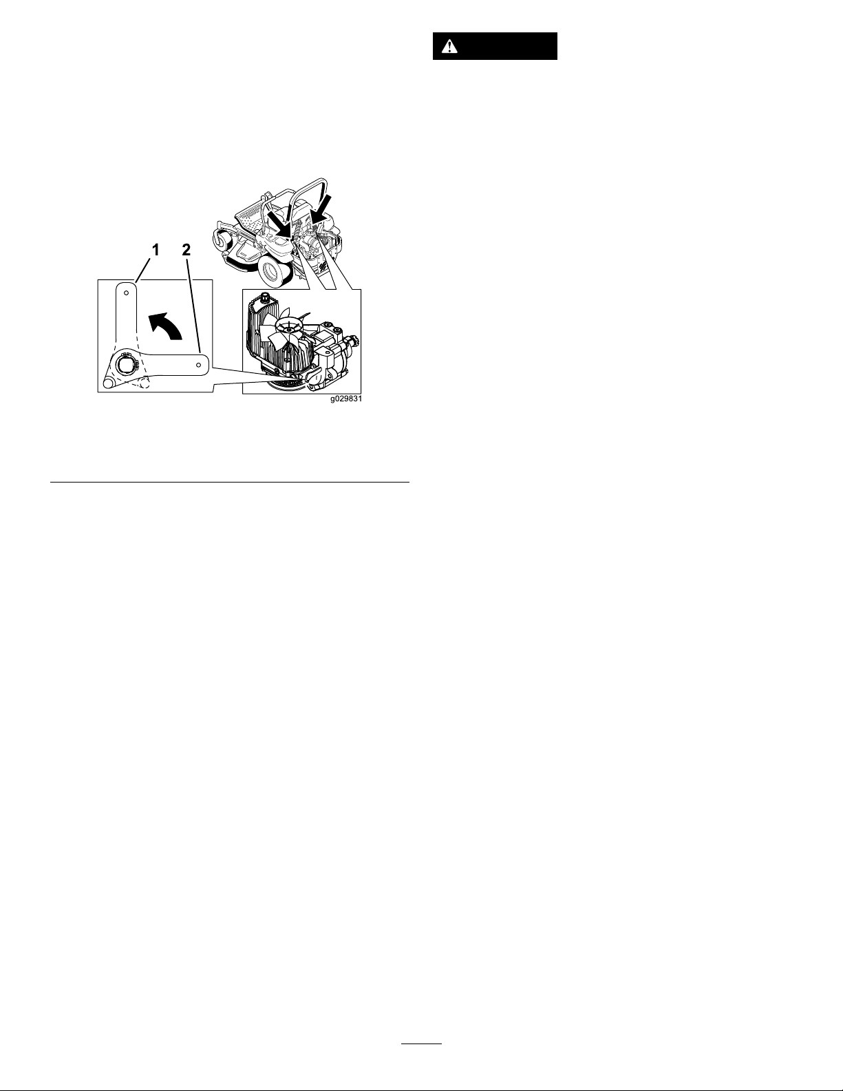
2.Rotatethereleasevalveleversverticallytopush
themachine.Thisallowshydraulicoiltoby-pass
thepumpenablingthewheelstoturn(Figure
39).
3.Disengageparkingbrakebeforepushing.
Figure39
1.Verticaltopushthe
machine
2.Horizontaltorunthe
machine
DANGER
Withoutagrassdeector,dischargecover,or
completegrasscatcherassemblymountedin
place,youandothersareexposedtoblade
contactandthrowndebris.Contactwith
rotatingmowerblade(s)andthrowndebris
willcauseinjuryordeath.
•Neverremovethegrassdeectorfrom
themowerbecausethegrassdeector
routesmaterialdowntowardtheturf.Ifthe
grassdeectoriseverdamaged,replaceit
immediately.
•Neverputyourhandsorfeetunderthe
mower.
•Nevertrytoclearthedischargeareaor
mowerbladesunlessyoumovethepower
takeoff(blade-controlswitch(PTO)tothe
offposition,rotatetheignitionkeytooff
g029831
andremovethekey .
•Makesurethegrassdeectorisinthe
downposition.
4.Rotatethereleasevalvelevershorizontallyto
runthemachine(Figure39).
UsingtheSideDischarge
Themowerhasahingedgrassdeectorthat
dispersesclippingstothesideanddowntowardthe
turf.
31
Page 32
TransportingtheMachine
LoadingtheMachine
Useaheavy-dutytrailerortrucktotransportthe
machine.Ensurethatthetrailerortruckhasall
necessarybrakes,lighting,andmarkingasrequired
bylaw.Pleasecarefullyreadallthesafetyinstructions.
Knowingthisinformationcouldhelpyou,yourfamily,
pets,orbystandersavoidinjury.
WARNING
Drivingonthestreetorroadwaywithout
turnsignals,lights,reectivemarkings,ora
slow-movingvehicleemblemisdangerous
andcanleadtoaccidentscausingpersonal
injury.
Donotdrivethemachineonapublicstreet
orroadway.
Totransportthemachine:
1.Ifusingatrailer,connectittothetowingvehicle
andconnectthesafetychains.
2.Ifapplicable,connectthetrailerbrakes.
3.Loadthemachineontothetrailerortruck.
4.Stoptheengine,removethekey,setthebrake,
andclosethefuelvalve.
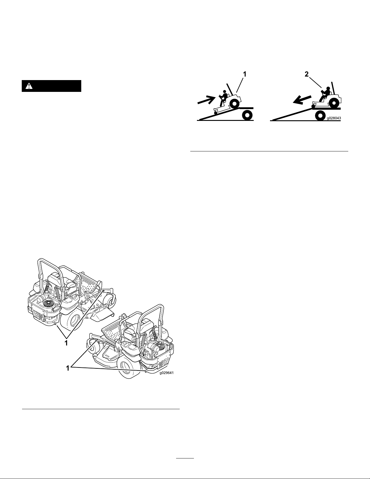
5.Usethemetaltie-downloopsonthemachineto
securelyfastenthemachinetothetrailerortruck
withstraps,chains,cable,orropes(Figure40).
Useextremecautionwhenloadingorunloading
machinesontoatraileroratruck.Useafull-width
rampthatiswiderthanthemachineforthisprocedure.
Backuprampsanddriveforwarddownramps(Figure
41).
Figure41
1.Backupramps
2.Driveforwarddownramps
Important:Donotusenarrowindividualramps
foreachsideofthemachine.
Ensuretherampislongenoughsothattheanglewith
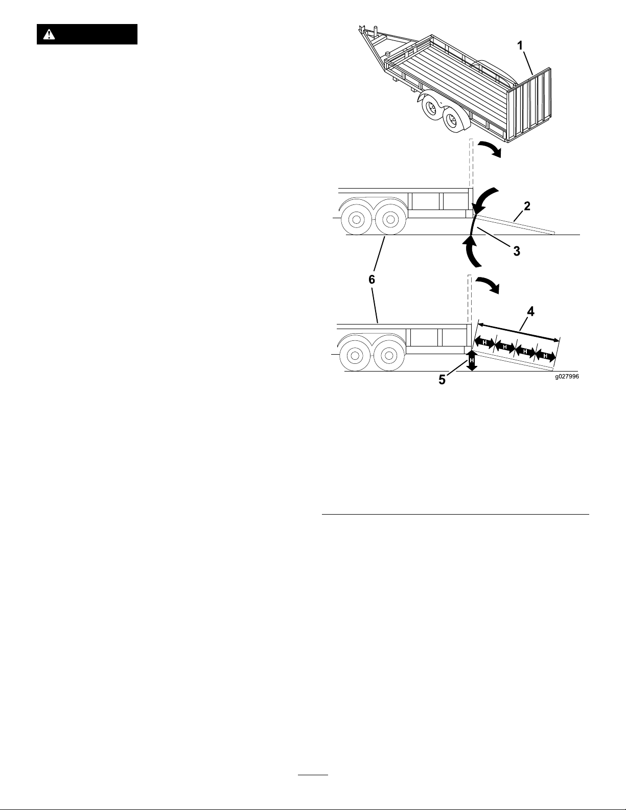
thegrounddoesnotexceed15degrees(Figure42).
Onatground,thisrequiresaramptobeatleastfour
times(4X)aslongastheheightofthetrailerortruck
bedtotheground.Asteeperanglemaycausemower
componentstogetcaughtastheunitmovesfromthe
ramptothetrailerortruck.Steeperanglesmayalso
causethemachinetotiporlosecontrol.Ifloadingon
ornearaslope,positionthetrailerortrucksothatitis
onthedownsideoftheslopeandtherampextends
uptheslope.Thiswillminimizetherampangle.
g028043
1.Tie-downloops
g029641
Figure40
32
Page 33
WARNING
Loadingamachineontoatrailerortruck
increasesthepossibilityoftip-overandcould
causeseriousinjuryordeath.
•Useextremecautionwhenoperatinga
machineonaramp.
•EnsurethattheROPSisintheupposition
andusetheseatbeltwhenloadingor
unloadingthemachine.Ensurethatthe
ROPSwillclearthetopofanenclosed
trailer.
•Useonlyafull-widthramp;donotuse
individualrampsforeachsideofthe
machine.
•Donotexceeda15-degreeanglebetween
therampandthegroundorbetweenthe
rampandthetrailerortruck.
•Ensurethelengthoframpisatleastfour
times(4X)aslongastheheightofthe
trailerortruckbedtotheground.Thiswill
ensurethatrampangledoesnotexceed15
degreesonatground.
•Backuprampsanddriveforwarddown
ramps.
•Avoidsuddenaccelerationordeceleration
whiledrivingthemachineonarampas
thiscouldcausealossofcontrolora
tip-oversituation.
1.Full-widthrampinstowed
position
2.Sideviewoffull-width
rampinloadingposition
3.Notgreaterthan
15degrees
g027996
Figure42
4.Rampisatleastfourtimes
(4X)aslongastheheight
ofthetrailerortruckbed
totheground
5.H=heightofthetraileror
truckbedtotheground
6.Trailer
33
Page 34

OperatingTips
FastThrottleSetting
Forbestmowingandmaximumaircirculation,operate
theengineatthefastthrottleposition.Airisrequired
tothoroughlycutgrassclippings,sodonotsetthe
height-of-cutsolowastototallysurroundthemower
byuncutgrass.Alwaystrytohaveonesideofthe
mowerfreefromuncutgrass,whichallowsairtobe
drawnintothemower.
CuttingaLawnfortheFirstTime
LongGrass
Ifthegrassiseverallowedtogrowslightlylongerthan
normal,orifitcontainsahighdegreeofmoisture,
raisethecuttingheighthigherthanusualandcutthe
grassatthissetting.Thencutthegrassagainusing
thelower,normalsetting.
WhenStopping
Ifyoumuststoptheforwardmotionofthemachine
whilemowing,aclumpofgrassclippingsmaydrop
ontoyourlawn.T oavoidthis,moveontoapreviously
cutareawiththebladesengaged.
Cutgrassslightlylongerthannormaltoensurethe
cuttingheightofthemowerdoesnotscalpanyuneven
ground.However,thecuttingheightusedinthepast
isgenerallythebestonetouse.Whencuttinggrass
longerthansixinchestall,youmaywanttocutthe
lawntwicetoensureanacceptablequalityofcut.
Cut1/3oftheGrassBlade
Itisbesttocutonlyabout1/3ofthegrassblade.
Cuttingmorethanthatisnotrecommendedunless
grassissparse,oritislatefallwhengrassgrows
moreslowly.
MowingDirection
Alternatemowingdirectiontokeepthegrassstanding
straight.Thisalsohelpsdisperseclippingswhich
enhancesdecompositionandfertilization.
MowatCorrectIntervals
Normally,moweveryfourdays.Butremember,
grassgrowsatdifferentratesatdifferenttimes.So
tomaintainthesamecuttingheight,whichisagood
practice,mowmoreofteninearlyspring.Asthe
grassgrowthrateslowsinmidsummer,mowless
frequently.Ifyoucannotmowforanextendedperiod,
rstmowatahighcuttingheight;thenmowagaintwo
dayslateratalowerheightsetting.
KeeptheUndersideoftheMower
Clean
Cleanclippingsanddirtfromtheundersideofthe
moweraftereachuse.Ifgrassanddirtbuildupinside
themower,cuttingqualitywilleventuallybecome
unsatisfactory.
BladeMaintenance
Maintainasharpbladethroughoutthecuttingseason
becauseasharpbladecutscleanlywithouttearingor
shreddingthegrassblades.T earingandshredding
turnsgrassbrownattheedges,whichslowsgrowth
andincreasesthechanceofdisease.Checkthe
cutterbladesdailyforsharpness,andforanywearor
damage.Filedownanynicksandsharpentheblades
asnecessary.Ifabladeisdamagedorworn,replaceit
immediatelywithagenuineTOROreplacementblade.
CuttingSpeed
Toimprovecutquality,useaslowergroundspeed
incertainconditions.
AvoidCuttingTooLow
Ifthecuttingwidthofthemoweriswiderthanthe
moweryoupreviouslyused,raisethecuttingheightto
ensurethatuneventurfisnotcuttooshort.
34
Page 35

Maintenance
RecommendedMaintenanceSchedule(s)
MaintenanceService
Interval
Aftertherst100hours
Aftertherst250hours
Beforeeachuseordaily
Every50hours
Every100hours
Every150hours
MaintenanceProcedure
•Checkthewheellugnuttorque.
•Checkthewheelhubslotted-nuttorque.
•Checktheparkingbrakeadjustment.
•Changethehydraulicltersandhydraulicoilwhenusinganytypeofoil.
•Checkthesafetysystem.
•Checktheengineoillevel.
•Checktheseatbelt.
•Checktherolloverprotectionsystem(ROPS)knobs.
•Cleantheenginescreenandtheoilcooler.
•Checkandcleanthehydraulicunitshrouds.
•Checkthemowerblades.
•Cleanthemowerdeck.
•Greasethemowerdeckspindlesandidlerarm.
•Checksparkarrester(ifequipped).
•Checkthetirepressure.
•Inspectthebeltsforcracksandwear.
•Checkthehydraulicoillevel.
•Lubricatethemowerdeckliftpivots.
•Changetheengineoil(moreoftenindirtyordustyconditions).
•Checkandcleanenginecoolingnsandshrouds.
•Inspecttheprimarylterandair-inletscreen.
Every200hours
Every250hours
Every300hours
Every500hours
Every600hours
Yearlyorbeforestorage
•Changetheengineoillter.
•Cleantheengineoilcooler.
•Checkandgapthesparkplug.
•Replacethefuellter(moreoftenindirtyordustyconditions).
•ChangethehydraulicltersandhydraulicoilwhenusingMobil®1oil(moreoftenin
dirtyordustyconditions).
•Replacetheprimaryairlter(moreoftenindustyorsandyconditions).
•Checktheinnerairlter.
•Checkthewheellugnuttorque.
•Checkthewheelhubslotted-nuttorque.
•Adjustthecasterpivotbearing.
•Checktheparkingbrakeadjustment.
•ChangethehydraulicltersandhydraulicoilwhenusingToro®HYPR-OIL™500
hydraulicoil(moreoftenindirtyordustyconditions).
•Replacetheinnerairlter.
Monthly
Yearly
•Checkthebattery.
•Greasethepumpbeltidlerarm.
•Greasethefrontcasterpivots(moreoftenindirtyordustyconditions).
•Repackthefrontcasterwheelbearings(moreoftenindirtyordustyconditions).
•Lubricatethecasterwheelhubs.
•Paintchippedsurfaces.
•Checkallmaintenanceprocedureslistedabovebeforestorage.
Important:Refertoyourengineoperator'smanualforadditionalmaintenanceprocedures.
35
Page 36
CAUTION
Ifyouleavethekeyintheignitionswitch,someonecouldaccidentlystarttheengineand
seriouslyinjureyouorotherbystanders.
Removethekeyfromtheignitionbeforeyoudoanymaintenance.
Lubrication
LubricatingtheMachine
Greasemorefrequentlywhenoperatingconditions
areextremelydustyorsandy.
GreaseType:No.2general-purposelithium-based
ormolybdenum-basedgrease
1.Disengagetheblade-controlswitch(PTO),move
themotion-controlleverstotheneutral-locked
positionandsettheparkingbrake.
2.Stoptheengine,removethekey ,andwait
forallmovingpartstostopbeforeleavingthe
operatingposition.
Figure44
g017050
3.Cleanthegreasettingswitharag.Makesure
toscrapeanypaintoffthefrontofthetting(s).
4.Connectagreaseguntothetting.Pump
greaseintothettingsuntilgreasebeginsto
oozeoutofthebearings.
5.Wipeupanyexcessgrease.
AddingLightOilorSpray Lubrication
ServiceInterval:Every100hours
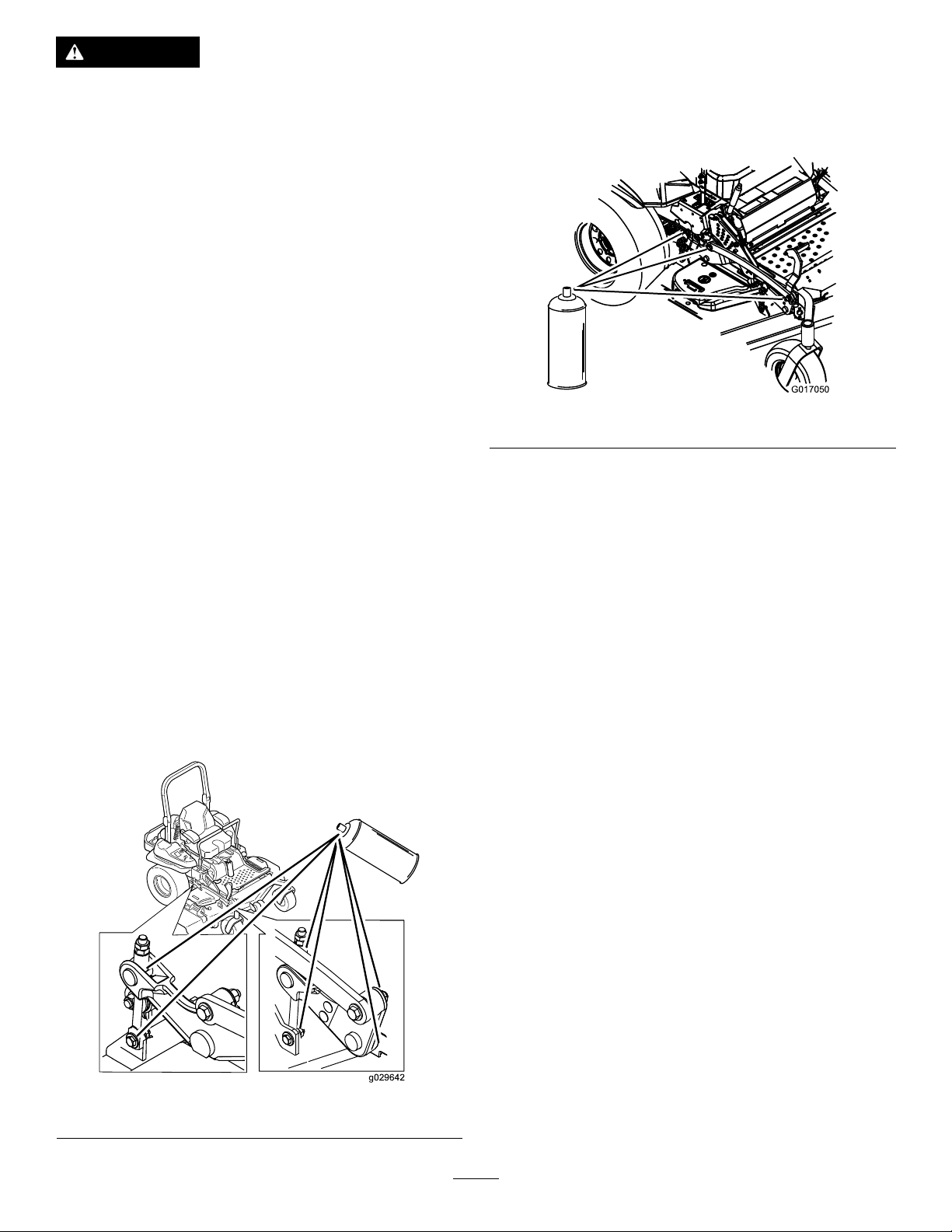
Lubricatethedeckliftpivots.
GreasingtheMower
ServiceInterval:Every50hours—Greasethemower
deckspindlesandidlerarm.
Yearly—Greasethepumpbeltidlerarm.
Yearly—Greasethefrontcasterpivots(more
oftenindirtyordustyconditions).
Yearly—Repackthefrontcasterwheelbearings
(moreoftenindirtyordustyconditions).
Important:Makesurethatthecuttingunit
spindlesarefullofgreaseweekly.
1.Disengagetheblade-controlswitch(PTO),move
themotion-controlleverstotheneutral-locked
position,andsettheparkingbrake.
2.Stoptheengine,removethekey ,andwait
forallmovingpartstostopbeforeleavingthe
operatingposition.
3.Greasethemowerdeckidlerpulleypivotuntil
greasecomeoutthebottom(Figure45).
4.Greasethe3spindlebearingsuntilgrease
comesoutthelowerseals(Figure45).
Figure43
g029642
36
Page 37
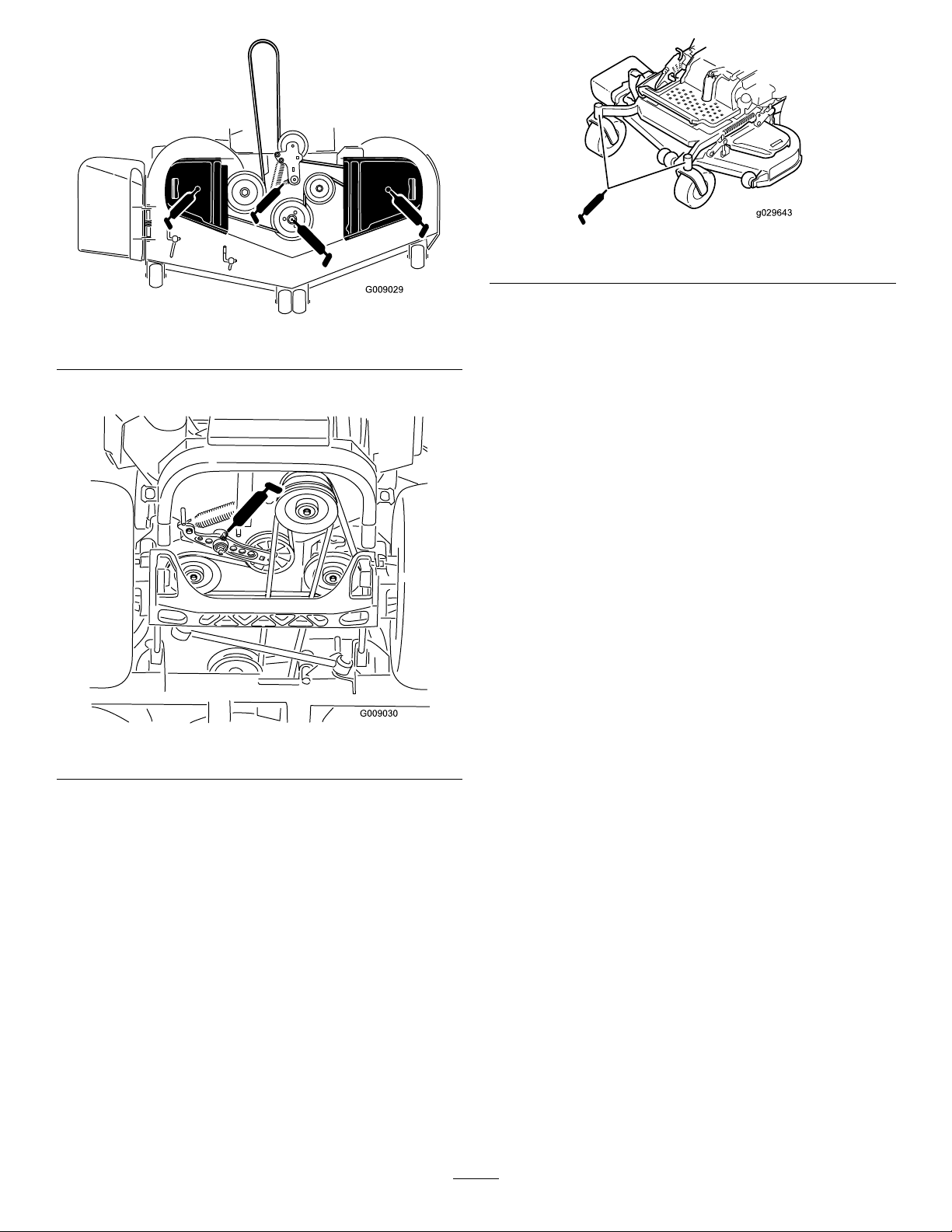
Figure45
5.Greasethedrivebeltidlerarm(Figure45).
g029643
Figure47
g009029
Figure46
6.Removethedustcapandadjustthecaster
pivots.
Note:Keepthedustcapoffuntilgreasingis
complete.RefertoAdjustingtheCasterPivot
Bearing(page52).
7.Removethehexplugandthreadagreasetting
intothehole.
8.Pumpgreaseintothettinguntilitoozesout
aroundthetopbearing.
9.Removethegreasettingfromthehole.
10.Installthehexpluganddustcap(Figure47).
g009030
37
Page 38
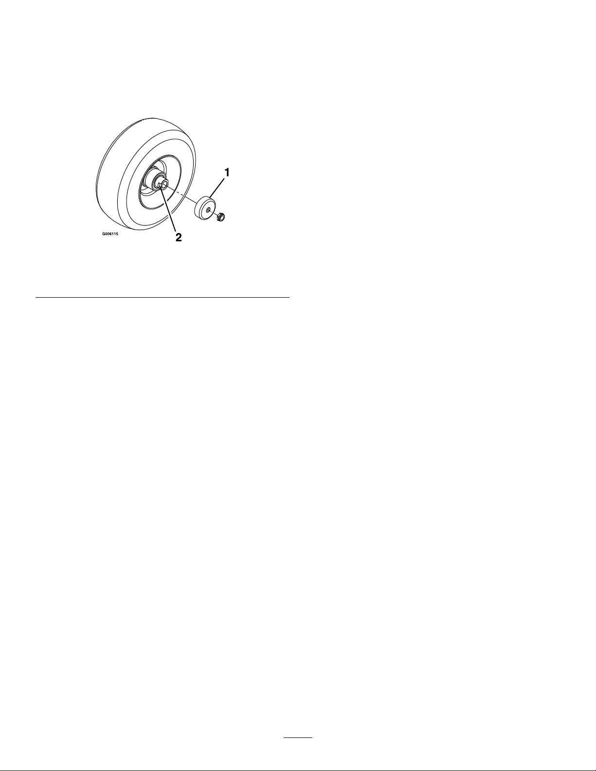
LubricatetheCasterWheel Hubs
ServiceInterval:Yearly
1.Stoptheengine,waitforallmovingpartstostop,
andremovethekey.Engagetheparkingbrake.
11.Withtheopenendofthewheelfacingup,ll
theareainsidethewheelaroundtheaxlefullof
general-purposegrease.
12.Insertthesecondbearingandnewsealintothe
wheel.
13.Applyathreadlockingadhesivetothesecond
spacernutandthreaditontotheaxlewiththe
wrenchatsfacingoutward.
14.Torquethenutto8-9N-m(75-80in-lb),loosen,
thenre-torqueto2-3N-m(20-25in-lb).
Note:Makesurethattheaxledoesnotextend
beyondeithernut.
15.Installthesealguardsoverthewheelhuband
insertthewheelintothecasterfork.Installthe
casterboltandtightenthenutfully.
Figure48
1.Sealguard2.Spacernutwithwrench
ats
2.Raisethefrontofthemachineupandsupportit
withjackstands.
3.Removethecasterwheelfromthecasterforks.
4.Removethesealguardsfromthewheelhub.
5.Remove1ofthespacernutsfromtheaxle
assemblyinthecasterwheel.
Note:Notethatthreadlockingadhesivehas
beenappliedtolockthespacernutstotheaxle.
Removetheaxle(withtheotherspacernutstill
assembledtoit)fromthewheelassembly.
6.Pryouttheseals,andinspectthebearingsfor
wearordamageandreplaceifnecessary.
7.Packthebearingswithageneral-purpose
grease.
8.Insert1bearingand1newsealintothewheel.
g006115
Important:Topreventsealandbearingdamage,
checkthebearingadjustmentoften.Spinthe
castertire.Thetireshouldnotspinfreely(more
than1or2revolutions)orhaveanysideplay.If
thewheelspinsfreely,adjustthetorqueonthe
spacernutuntilthereisaslightamountofdrag.
Applythreadlockingadhesive.
Note:Thesealsmustbereplaced.
9.Iftheaxleassemblyhashadbothspacernuts
removed(orbrokenloose),applyathread
lockingadhesiveto1spacernutandthread
itontotheaxlewiththewrenchatsfacing
outward.
Note:Donotthreadthespacernutallof
thewayontotheendoftheaxle.Leave
approximately3mm(1/8inch)fromtheouter
surfaceofthespacernuttotheendoftheaxle
insidethenut.
10.Inserttheassemblednutandaxleintothewheel
onthesideofthewheelwiththenewsealand
bearing.
38
Page 39
EngineMaintenance
WARNING
Contactwithhotsurfacesmaycausepersonal
injury.
Keephands,feet,face,clothing,andother
bodypartsawaythemuferandotherhot
surfaces.
ServicingtheAirCleaner
ServiceInterval:Every150hours
Every300hours/Yearly(whichevercomes
rst)—Replacetheprimaryairlter(moreoften
industyorsandyconditions).
Every300hours—Checktheinnerairlter.
Every600hours—Replacetheinnerairlter.
Note:Checktheltersmorefrequentlyifthe
operatingconditionsareextremelydustyorsandy .
RemovingtheFilters
1.DisengagethePTO,movethemotion-control
leverstotheneutral-lockedposition,andsetthe
parkingbrake.
2.Stoptheengine,removethekey ,andwait
forallmovingpartstostopbeforeleavingthe
operatingposition.
3.Releasethelatchesontheaircleanerand
pulltheair-inletcoverofftheair-cleanerbody
(Figure49).
4.Cleantheair-inletscreenandcover.
5.Installtheair-inletcoverandsecureitwiththe
latches(Figure49).
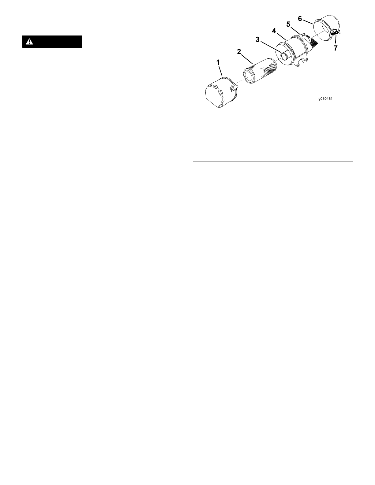
Figure49
1.Cover
2.Primarylter6.Cover
3.Innerlter
4.Air-cleanerbody
6.Releasethelatchesontheaircleanerandpull
theair-cleanercoverofftheair-cleanerbody
(Figure49).
7.Cleantheinsideoftheair-cleanercoverwith
compressedair.
8.Gentlyslidetheprimarylteroutofthe
air-cleanerbody(Figure49).
5.Air-inletscreen
7.Latch
Note:Avoidknockingthelterintothesideof
thebody.
9.Removetheinnerlteronlyifyouintendto
replaceit.
Important:Neverattempttocleanthe
innerlter.Ifthesafetylterisdirty,then
theprimarylterisdamaged;replaceboth
lters.
10.Inspecttheprimarylterfordamagebylooking
intothelterwhileshiningabrightlightonthe
outsideofthelter.
g030481
Note:Anyholesinthelterwillappearasbright
spots.Ifthelterisdamaged,discardit.
ServicingthePrimaryFilter
•Iftheprimarylterisdirty,bent,ordamaged,
replaceit.
•Donotcleantheprimarylter.
ServicingtheSafetyFilter
Replacethesafetylter,nevercleanit.
Important:Neverattempttocleanthesafety
lter.Ifthesafetylterisdirty ,thentheprimary
lterisdamaged.Replacebothlters.
39
Page 40
InstallingtheFilters
Important:Topreventenginedamage,always
operatetheenginewithbothairltersandcover
installed.
1.Ifinstallingnewlters,checkeachlterfor
shippingdamage.Donotuseadamagedlter.
2.Iftheinnerlterisbeingreplaced,carefullyslide
itintothelterbody(Figure49).
3.Carefullyslidetheprimarylterovertheinner
lter(Figure49).
Note:Ensurethattheprimarylterisfully
seatedbypushingonitsouterrimwhileinstalling
it.
Important:Donotpressonthesoftinside
areaofthelter.
4.Installtheaircleanercoverandsecurethe
latches(Figure49).
ServicingtheEngineOil
OilType:Detergentoil(APIserviceclassSL,SM,
SN,orhigher)
OilCapacity:withalterchange,1.7L(1.8USqt);
withnolterchange,1.4L(1.5USqt)
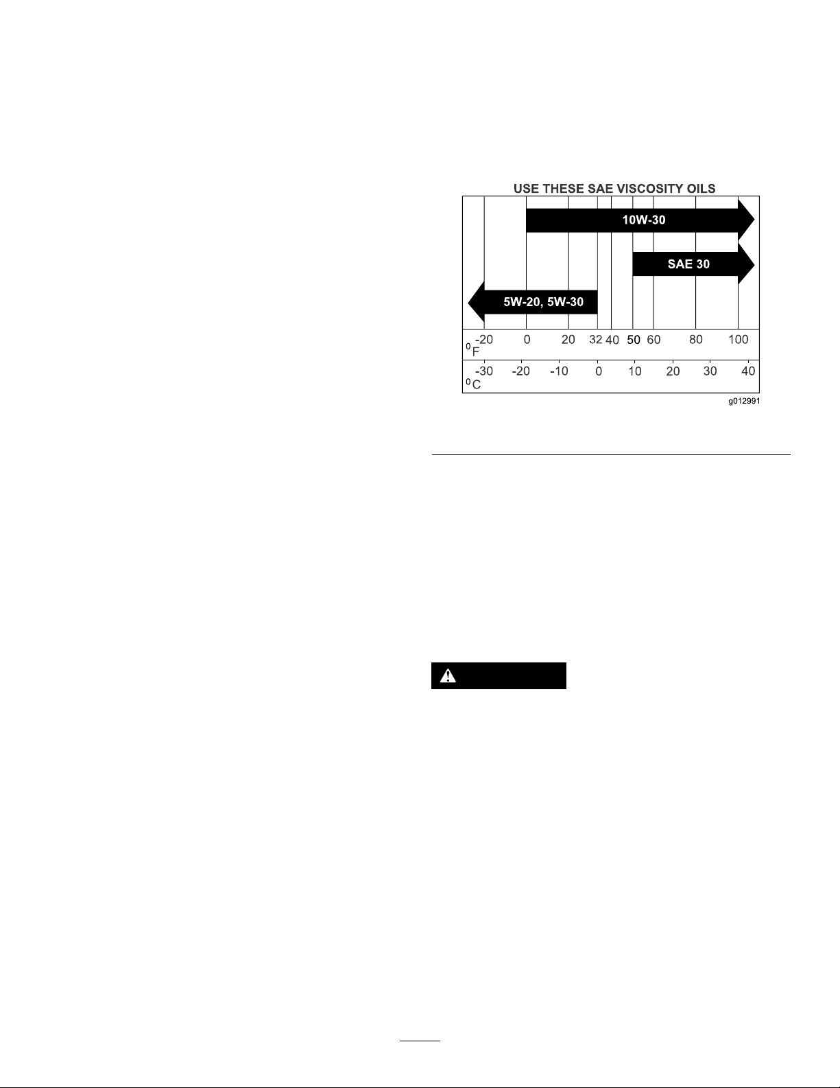
Viscosity:Seethetablebelow.
g012991
Figure50
Note:Useofsyntheticoilhaving5W-20or5W-30
ratingisacceptable,upto4degreesC(40degreesF).
Note:Syntheticoilswillprovidebetterstartingin
extremecoldbelow-23degreesC(-10degreesF).
CheckingtheEngine-OilLevel
ServiceInterval:Beforeeachuseordaily
Note:Checktheoilwhentheengineiscold.
WARNING
Contactwithhotsurfacesmaycausepersonal
injury.
Keephands,feet,face,clothingandother
bodypartsawayfromthemuferandother
hotsurfaces.
Important:Donotoverllthecrankcasewithoil
becausedamagetotheenginemayresult.Donot
runenginewithoilbelowthelowmarkbecause
theenginemaybedamaged.
1.DisengagethePTO,movethemotion-control
leverstotheneutral-lockedpositionandsetthe
parkingbrake.
2.Stoptheengine,removethekey ,andwait
forallmovingpartstostopbeforeleavingthe
operatingposition(Figure51).
40
Page 41
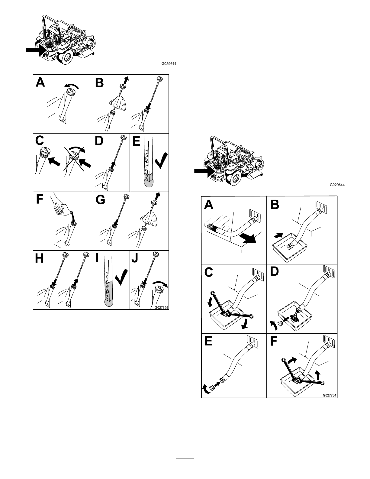
ChangingtheEngineOil
ServiceInterval:Every100hours(moreoftenindirty
ordustyconditions).
Note:Disposeoftheusedoilatarecyclingcenter.
g029644
1.Parkthemachinesothattherearisslightly
lowerthanthefronttoensurethattheoildrains
completely.
2.DisengagethePTO,movethemotion-control
leverstotheneutral-lockedposition,andsetthe
parkingbrake.
3.Stoptheengine,removethekey ,andwait
forallmovingpartstostopbeforeleavingthe
operatingposition(Figure52).
g029644
Figure51
g027659
g027734
Figure52
41
Page 42
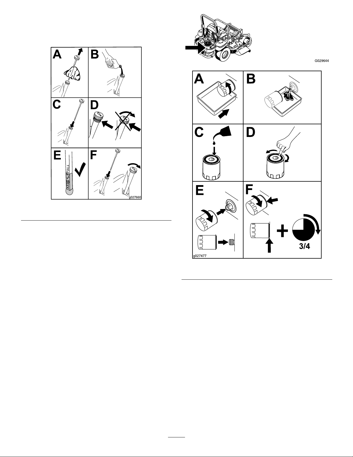
4.Slowlypourapproximately80%ofthespecied
oilintothellertubeandslowlyaddthe
additionaloiltobringittotheFullmark(Figure
53).
g029644
Figure53
5.Starttheengineanddrivetoaatarea.Check
theoillevelagain.
ChangingtheEngine-OilFilter
ServiceInterval:Every200hours
Note:Changetheengineoilltermorefrequently
whenoperatingconditionsareextremelydustyor
sandy.
1.Draintheoilfromtheengine;refertoChanging
theEngineOil(page41).
2.Changetheengineoillter(Figure54).
g027660
g027477
Figure54
Note:Ensuretheoilltergaskettouchesthe
engineandthenanextra3/4turniscompleted.
3.Fillthecrankcasewiththepropertypeofnew
oil;refertoChangingtheEngineOil(page41).
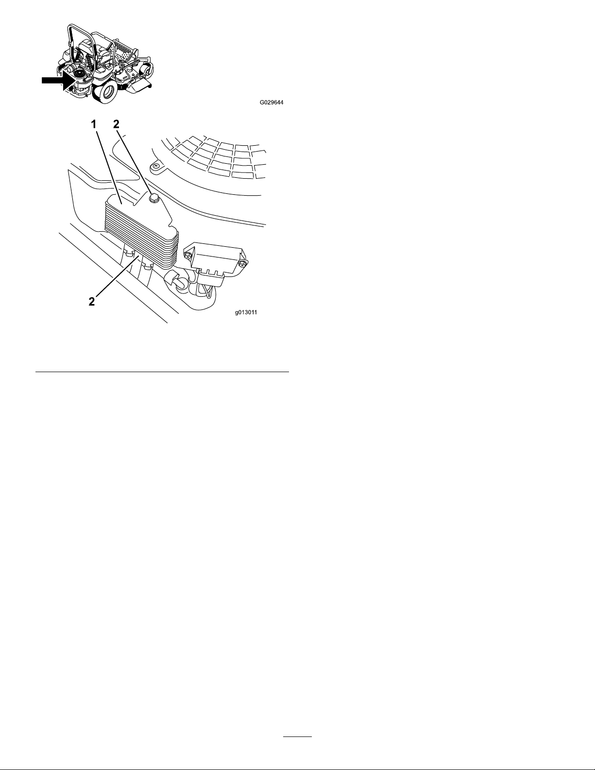
ServicingtheEngine-OilCooler
ServiceInterval:Every200hours
1.Keeptheoilcoolerfreeofdebris.bycleaning
thenswithabrush.
2.Removetheboltsholdingtheoilcoolertothe
enginehousing.
3.Cleantheinsideoftheoilcoolerwithabrush.
4.Installtheoilcoolertotheenginehousing.
42
Page 43
ServicingtheSparkPlugs
ServiceInterval:Every200hours—Checkandgap
thesparkplug.
Makesurethattheairgapbetweenthecenterand
sideelectrodesiscorrectbeforeinstallingthespark
g029644
plugs.Useaspark-plugwrenchforremovingand
installingthesparkplugsandagappingtool/feeler
gaugetocheckandadjusttheairgap.Installnew
sparkplugsifnecessary.
Figure55
1.Engineoilcooler2.Bolts
g013011
Type:Champion
®
XC12YC,Champion
®
Platinum
3071orequivalent
AirGap:0.76mm(0.030inch)
RemovingtheSparkPlugs
1.Stoptheengine,removethekey ,andwait
forallmovingpartstostopbeforeleavingthe
operatingposition.
2.DisengagethePTO,movethemotion-control
leverstotheneutral-lockedpositionandsetthe
parkingbrake.
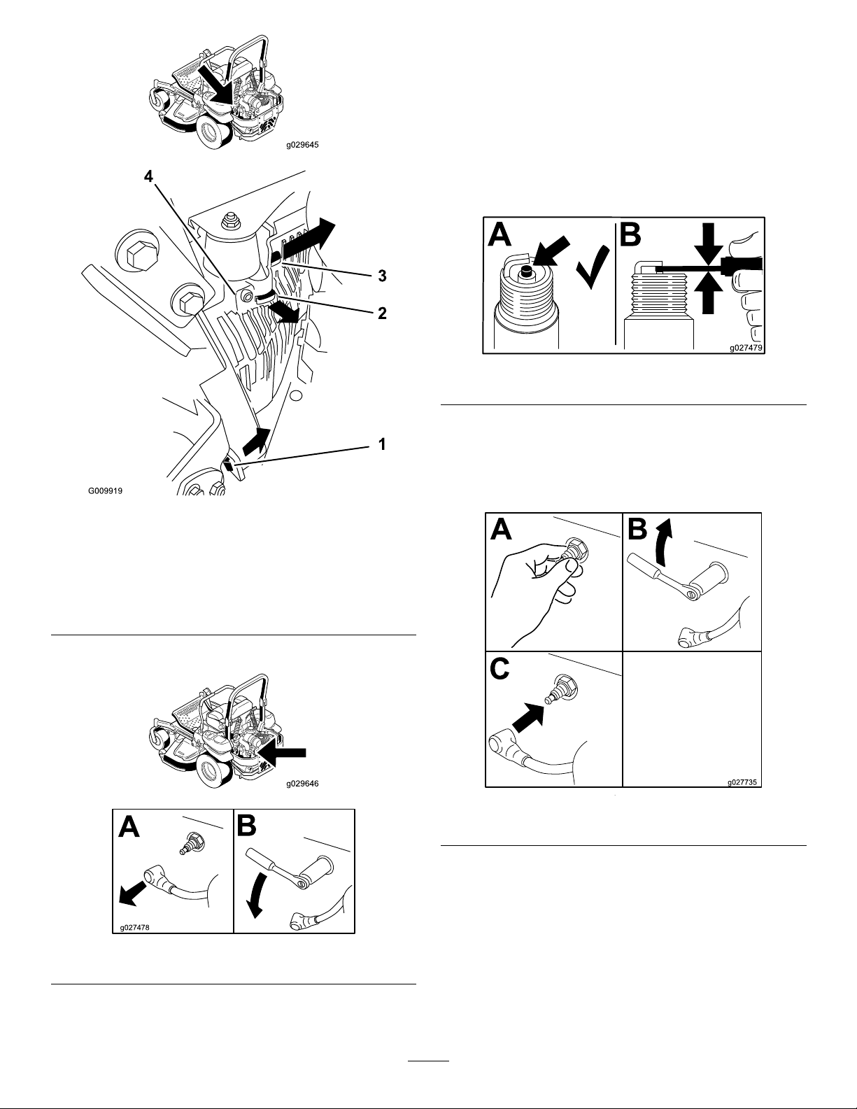
3.Removetheleft-handhydraulicunitshroudin
theorderlistedwithFigure56.
Note:Thisgivesyouaccesstothefrontspark
plug.
43
Page 44
CheckingtheSparkPlugs
Important:Replacethesparkplugswhenthey
have:ablackcoating,wornelectrodes,anoily
lm,cracksorreuseisquestionable.
Ifyouseelightbrownorgrayontheinsulator,the
g029645
engineisoperatingproperly.Ablackcoatingonthe
insulatorusuallymeansthattheaircleanerisdirty.
Setthegapto0.76mm(0.030inch).
g027479
Figure58
InstallingtheSparkPlugs
1.Pullthistabouttothe
sideinthedirectionofthe
arrow.
2.Pulltheshroudoffofthis
frametabinthedirection
ofthearrow.
4.Removethesparkplugs.
Figure56
3.Pulltheshroudoffofthis
frametabinthedirection
ofthearrow.
4.Shroud
Tightenthesparkplugsto24.4to29.8N-m(18to
g009919
g029646
22ft.-lb).
g027735
Figure59
Figure57
5.Installthelefthandhydraulicunitshroud(Figure
56).
g027478
44
Page 45

CheckSparkArrester(if
FuelSystem
equipped)
ServiceInterval:Every50hours
WARNING
Hotexhaustsystemcomponentsmayignite
gasolinevaporsevenaftertheengineis
stopped.Hotparticlesexhaustedduring
engineoperationmayigniteammable
materials.Firemayresultinpersonalinjury
orpropertydamage.
Donotfuelorruntheengineunlessspark
arresterisinstalled.
1.Stopengine,waitforallmovingpartstostop,
andremovekey.Engageparkingbrake.
2.Waitformufertocool.
3.Ifanybreaksinthescreenorweldsare
observed,replacethearrester.
4.Ifpluggingofthescreenisobserved,remove
thearresterandshakelooseparticlesoutof
thearresterandcleanscreenwithawirebrush
(soakinsolventifnecessary).Reinstallarrester
onexhaustoutlet.
Maintenance
WARNING
Fuelsystemcomponentsareunderhigh
pressure.Theuseofimpropercomponents
canresultinsystemfailure,gasolineleakage,
andpossibleexplosion.
Useonlyapprovedfuellinesandfuellters.
ServicingtheElectronic FuelInjectionSystem
Thismachinecontainsanelectronicfuelinjection
system.Itcontrolsthefuelowunderdifferent
operatingconditions.
Theelectroniccontrolunit(ECU)continuously
monitorstheoperationoftheEFIsystem.
Ifaproblemorfaultwithinthesystemisdetected,the
malfunctionindicatorlight(MIL)isilluminated.The
MIListheredlightlocatedintherightconsolepanel.
OncetheMILilluminates,initialtroubleshooting
checksshouldbemade.RefertotheMILsection
underTroubleshooting.
Ifthesechecksdonotcorrecttheproblem,further
diagnosisandservicingbyanAuthorizedService
Dealerisnecessary.
Replacingthe Low-PressureFuelFilter
ServiceInterval:Every200hours/Y early(whichever
comesrst)(moreoftenindirtyor
dustyconditions).
Thefuellterislocatedneartheengineonthefront
orrearsideoftheengine.
1.DisengagethePTO,movethemotion-control
leverstotheneutral-lockedposition,andsetthe
parkingbrake.
2.Stoptheengine,removethekey ,andwait
forallmovingpartstostopbeforeleavingthe
operatingposition.
3.Allowthemachinetocooldown.
4.Closethefuel-shutoffvalveundertheseat
(Figure60).
45
Page 46
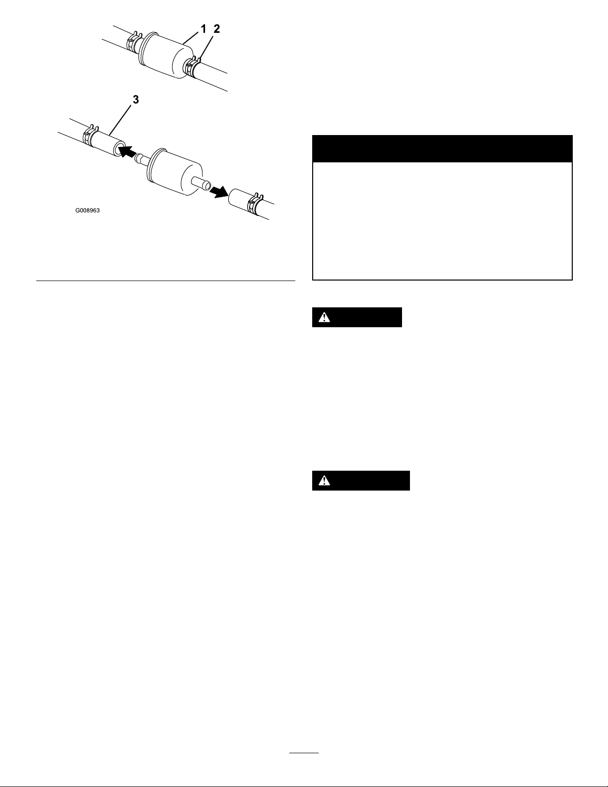
Figure60
1.Fuellter
2.Hoseclamp
5.Squeezetheendsofthehoseclampstogether
andslidethemawayfromthelter(Figure60).
6.Removethelterfromthefuellines.
7.Installanewlterandmovethehoseclamps
closetothelter(Figure60).
8.Openthefuel-shutoffvalve.
Note:Itisimportanttoinstallthefuellinehosesand
securethemwithplastictiesthesameastheywere
originallyinstalledatthefactory,tokeepthefuelline
awayfromcomponentsthatcouldcausefuelline
damage.
3.Fuelline
ElectricalSystem
Maintenance
ServicingtheBattery
ServiceInterval:Monthly
WARNING
CALIFORNIA
Proposition65Warning
Batteryposts,terminals,andrelated
g008963
Batteryelectrolytecontainssulfuricacid
whichisadeadlypoisonandcausessevere
burns.
Donotdrinkelectrolyteandavoidcontact
withskin,eyesorclothing.Wearsafety
glassestoshieldyoureyesandrubbergloves
toprotectyourhands.
RemovingtheBattery
accessoriescontainleadandlead
compounds,chemicalsknownto
theStateofCaliforniatocause
cancerandreproductiveharm.Wash
handsafterhandling.
DANGER
Servicingthe High-PressureFuelFilter
Donotattempttoservicethehigh-pressurefuellter.
Thehigh-pressurelterisintegratedwithinthefuel
pumpmodule.Thefuellterandothercomponents
insidethefuelpumpmodulearenotserviceable.Do
notattempttoopenthefuelpumpmodule.
EnsurethatanAuthorizedServiceDealerreplaces
thefuelpumpmodulewiththehigh-pressurefuellter.
ServicingtheFuelTank
Donotattempttodrainthefueltank.Ensurethatan
AuthorizedServiceDealerdrainsthefueltank.
WARNING
Batteryterminalsormetaltoolscouldshort
againstmetalmachinecomponentscausing
sparks.Sparkscancausethebatterygases
toexplode,resultinginpersonalinjury.
•Whenremovingorinstallingthebattery,
donotallowthebatteryterminalstotouch
anymetalpartsofthemachine.
•Donotallowmetaltoolstoshortbetween
thebatteryterminalsandmetalpartsofthe
machine.
46
Page 47
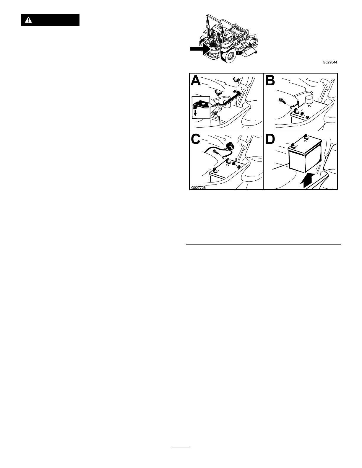
WARNING
Incorrectbatterycableroutingcoulddamage
themachineandcablescausingsparks.
Sparkscancausethebatterygasesto
explode,resultinginpersonalinjury.
•Alwaysdisconnectthenegative(black)
batterycablebeforedisconnectingthe
positive(red)cable.
•Alwaysconnectthepositive(red)battery
cablebeforereconnectingthenegative
(black)cable.
1.Disengagetheblade-controlswitch(PTO),move
themotion-controlleverstotheneutral-locked
positionandsettheparkingbrake.
2.Stoptheengine,removethekey ,andwait
forallmovingpartstostopbeforeleavingthe
operatingposition.
3.Firstdisconnectthenegativebatterycable
(black)fromthenegative(-)(black)battery
terminal(Figure61).
4.Slidetheredterminalbootoffthepositive(red)
batteryterminalandremovethepositive(+)(red)
batterycable(Figure61).
5.Removethewingnutsecuringthebatteryclamp
(Figure61).
6.Removetheclamp(Figure61).
1.Removethewingnutand
clamp
2.Removethenegative
batterycablebeforethe
positive
g029644
g027728
Figure61
3.Removethepositive
batterycable
4.Removebattery
7.Removethebattery .
InstallingtheBattery
1.Positionbatteryinthetraywiththeterminal
postsoppositefromthehydraulictank(Figure
61).
2.First,installthepositive(red)batterycableto
positive(+)batteryterminal.
3.Theninstallthenegative(black)batterycable
andgroundwiretothenegative(-)battery
terminal.
4.Securethecableswith2bolts,2washers,and
2locknuts(Figure61).
5.Slidetheredterminalbootontothepositive
(red)batterypost.
6.Installtheclampandsecureitwiththewingnut
(Figure61).
47
Page 48
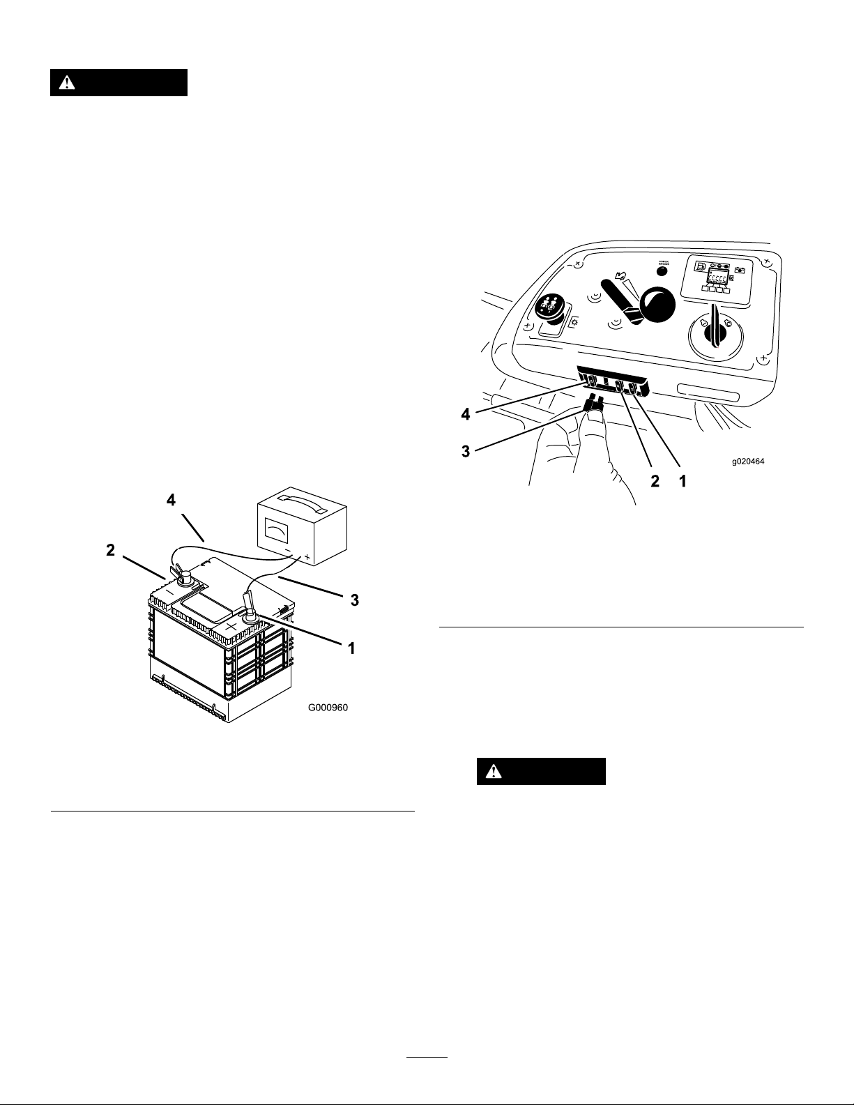
ChargingtheBattery
ServicingtheFuses
WARNING
Chargingthebatteryproducesgasesthatcan
explode.
Neversmokenearthebatteryandkeepsparks
andamesawayfrombattery.
Important:Alwayskeepthebatteryfullycharged
(1.265specicgravity).Thisisespecially
importanttopreventbatterydamagewhenthe
temperatureisbelow0°C(32°F).
1.Chargebatteryfor10to15minutesat25to30
ampsor30minutesat10amps.
2.Whenthebatteryisfullycharged,unplug
thechargerfromtheelectricaloutlet;then
disconnectthechargerleadsfromthebattery
posts(Figure62).
3.Installthebatteryinthemachineandconnect
thebatterycables,refertoInstallingtheBattery.
Note:Donotrunthemachinewiththebattery
disconnected;electricaldamagemayoccur.
Theelectricalsystemisprotectedbyfuses.Itrequires
nomaintenance;however,ifafuseblowscheckthe
component/circuitforamalfunctionorshort.
1.Thefusesarelocatedonrighthandconsole
nexttotheseat(Figure63).
2.Toreplacethefuses,pulloutonthefuseto
removeit.
3.Installanewfuse(Figure63).
1.Positivebatterypost
2.Negativebatterypost
Figure62
3.Red(+)chargerlead
4.Black(-)chargerlead
g020464
Figure63
1.Optional
accesory—15amp
2.Charge—25amp5.Console
3.PTO—10amp
4.Main—25amp
Jump-StartingtheMachine
1.Checkandcleancorrosionfromthebattery
g000960
terminalsbeforejump-starting.Ensurethatthe
connectionsaretight.
CAUTION
Corrosionorlooseconnectionscan
causeunwantedelectricalvoltagespikes
atanytimeduringthejump-starting
procedure.
Donotattempttojump-startwithloose
orcorrodedbatteryterminals,ordamage
totheengineorEFImayoccur.
48
Page 49
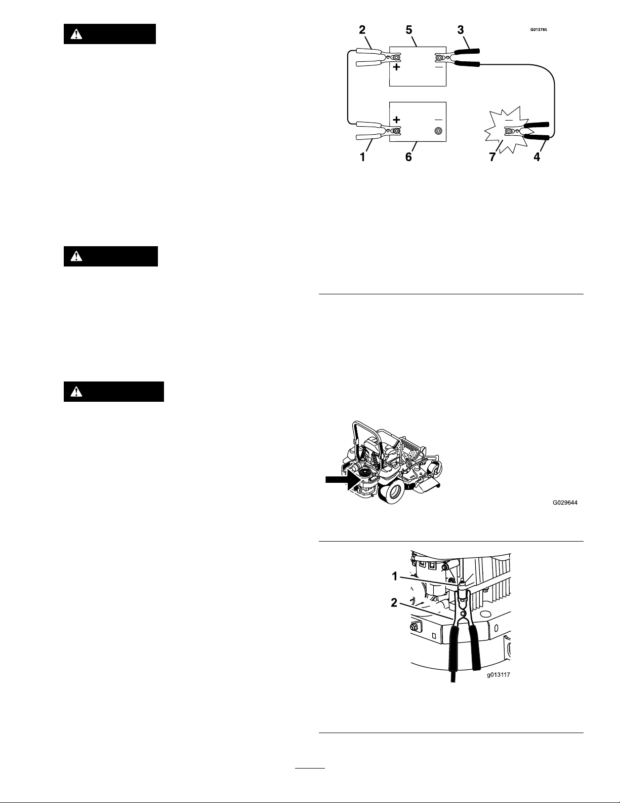
DANGER
Jump-startingaweakbatterythatis
crackedorfrozen,orhasalowelectrolyte
leveloranopen/shortedbatterycellcan
causeanexplosionresultinginserious
personalinjury.
Donotjump-startaweakbatteryifthese
conditionsexist.
2.Makesurethattheboosterbatteryisagoodand
fullychargedlead-acidbatteryat12.6voltsor
greater.Useproperlysizedjumpercableswith
shortlengthstoreducevoltagedropbetween
systems.Makesurethatthecablesarecolor
codedorlabeledforthecorrectpolarity.
CAUTION
Connectingthejumpercablesincorrectly
(wrongpolarity)canimmediatelydamage
theEFIsystem.
Becertainofbatteryterminalpolarity
andjumpercablepolaritywhenhooking
upbatteries.
WARNING
Batteriescontainacidandproduce
explosivegases.
•Shieldtheeyesandfacefromthe
batteriesatalltimes.
Figure64
1.Positive(+)cableon
dischargedbattery
2.Positive(+)cableon
boosterbattery
3.Negative(–)cableonthe
boosterbattery
4.Negative(–)cableonthe
engineblock
5.Boosterbattery
6.Dischargedbattery
7.Engineblock
4.Connecttheotherendofthepositivecableto
thepositiveterminaloftheboosterbattery.
5.Connecttheblacknegative(–)cabletotheother
terminal(negative)oftheboosterbattery.
6.Makethenalconnectionontheengine
blockofthestalledvehicle(nottothe
negativebatterypost)awayfromthebattery
andstandback(Figure66).
g012785
•Donotleanoverthebatteries.
Note:Besuretheventcapsaretightandlevel.
Placeadampcloth,ifavailable,overanyvent
capsonbothbatteries.Besurethevehiclesdo
nottouchandthatbothelectricalsystemsareoff
andatthesameratedsystemvoltage.These
instructionsarefornegativegroundsystems
only.
3.Connectthepositive(+)cabletothepositive(+)
terminalofthedischargedbatterythatiswired
tothestarterorsolenoidasshowninFigure64.
1.Engineblock
g029644
Figure65
g013117
Figure66
2.Negative(–)cable
49
Page 50

7.Startthevehicleandremovethecablesinthe
reverseorderofconnection(theengineblock
(black)connectionisthersttodisconnect).
DriveSystem
Maintenance
CheckingtheSeatBelt
ServiceInterval:Beforeeachuseordaily
Visuallyinspectseatbeltforwear,cuts,andproper
operationofretractorandbuckle.Replacebefore
operatingifdamaged.
CheckingtheKnobsonthe RolloverProtectionSystem (ROPS)
ServiceInterval:Beforeeachuseordaily
WARNING
Toavoidinjuryordeathfromrollover:keep
therollbarinthefullyraisedlockedposition
andusetheseatbelt.
Ensurethattherearpartoftheseatissecured
withtheseatlatch.
Checkthatboththemountinghardwareandtheknobs
areingoodworkingcondition.Makesuretheknobs
arefullyengagedwiththeROPSinthefullyraised
position.Theupperhoopoftherollbarmayneed
tobepushedforwardorpulledrearwardtogetboth
knobsfullyengaged.
50
Page 51
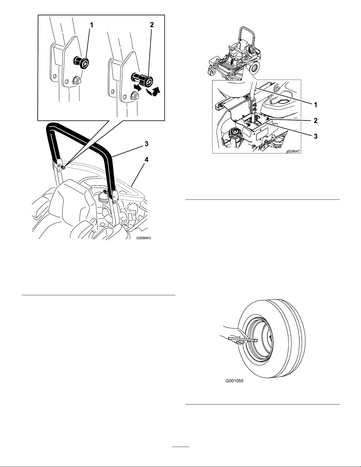
8.Tightenthestopplate(Figure68).
Figure68
Leftcontrollevershown
1.Controllever3.Stopplate
2.Bolt
g029647
Figure67
1.ROPSknob(locked
position)
2.PullROPSknoboutand
rotate90degreesto
changerollbarposition
3.Rollbarintheupright
position
4.Rollbarinthefolded
position
AdjustingtheTracking
1.Disengagetheblade-controlswitch(PTO).
2.Drivetoanopenatarea,movethe
motion-controlleverstotheneutral-locked
position.
3.Movethethrottlemidwaybetweenfastandslow.
4.Movebothmotion-controlleversalltheway
forwarduntiltheybothhitthestopsintheT-slot.
5.Checkwhichwaythemachinetracks.
6.Ifittrackstotheright,loosentheboltsandadjust
theleftstopplaterearwardontheleftT-slotuntil
themachinetracksstraight(Figure68).
7.Ifittrackstotheleft,loosentheboltsandadjust
therightstopplaterearwardontherightT-slot
untilthemachinetracksstraight(Figure68).
CheckingtheTirePressure
ServiceInterval:Every50hours/Monthly(whichever
g008943
Maintaintheairpressureinthereartiresat90kPa
(13psi).Uneventirepressurecancauseunevencut.
Checkthetireswhentheyarecold,togetthemost
accuratepressurereading.
Note:Thefronttiresaresemi-pneumatictiresanddo
notrequireairpressuremaintenance.
comesrst)
g001055
Figure69
51
Page 52
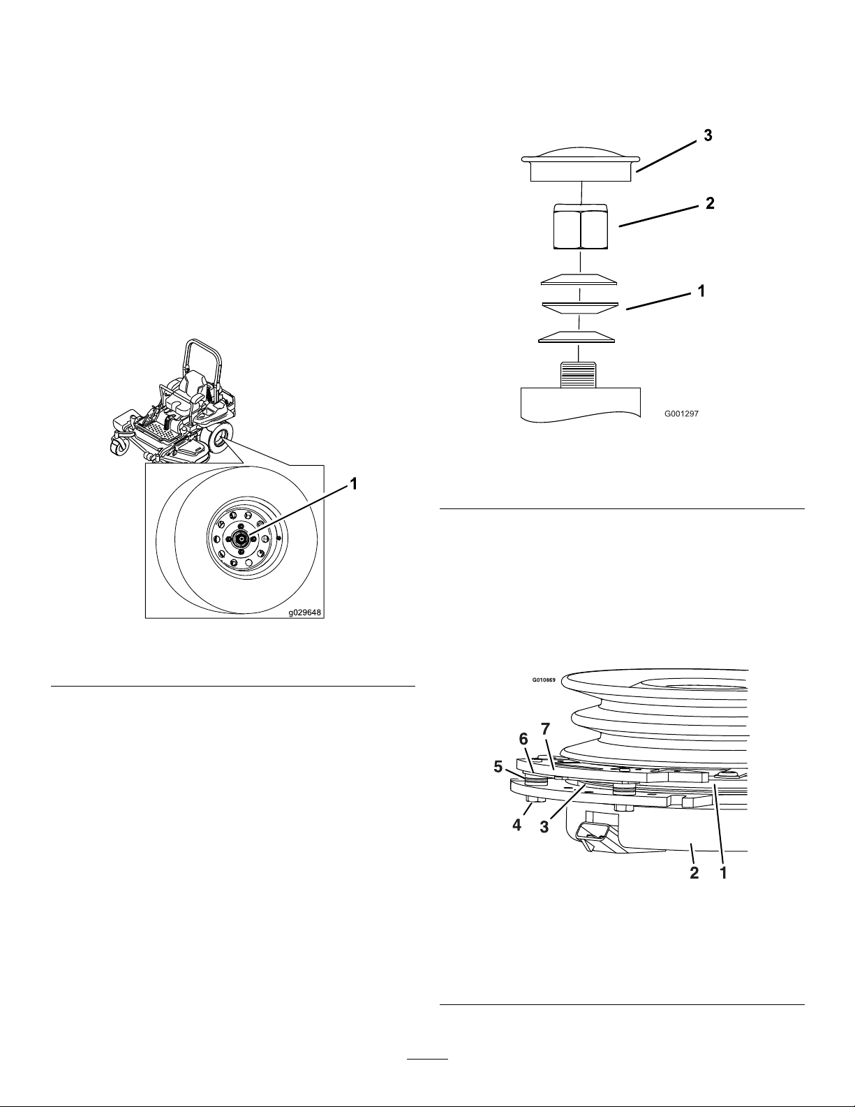
CheckingtheWheelLug Nuts
Checkandtorquethewheellugnutsto122to129
N-m(90to95ft-lb).
CheckingtheWheelHub SlottedNut
ServiceInterval:Aftertherst100hours
Every500hours
Checkandensurethatthetorqueoftheslottednutis
286to352N-m(211to260ft-lb).
Note:Donotuseanti-seizeonwheelhub.
Important:Makesurethatthespring
washersareinstalledcorrectlyasshownin
Figure71.
5.Installthedustcap(Figure71).
g001297
Figure71
Figure70
1.Slottednut
AdjustingtheCasterPivot Bearing
ServiceInterval:Every500hours/Y early(whichever
comesrst)
1.Disengagetheblade-controlswitch(PTO),move
themotion-controlleverstotheneutral-locked
positionandsettheparkingbrake.
2.Stoptheengine,removethekey ,andwait
forallmovingpartstostopbeforeleavingthe
operatingposition.
3.Removethedustcapfromthecasterandtighten
thelocknut(Figure71).
4.Tightenthelocknutuntilthespringwashersare
atandthenbackoffa1/4turntoproperlyset
thepre-loadonthebearings(Figure71).
1.Springwashers
2.Locknut
3.Dustcap
UsingtheClutchShim
Somelatermodelyearunitshavebeenbuiltwith
clutchesthatcontainabrakeshim.Whentheclutch
g029648
brakehasworntothepointwheretheclutchnolonger
engagesconsistently,theshimcanberemovedto
extendtheclutchlife.
g010869
Figure72
1.Armature5.Brakespacer
2.Fieldshell6.Re-gapshim
3.Rotor7.Brakepole
4.Brakemountingbolt
52
Page 53
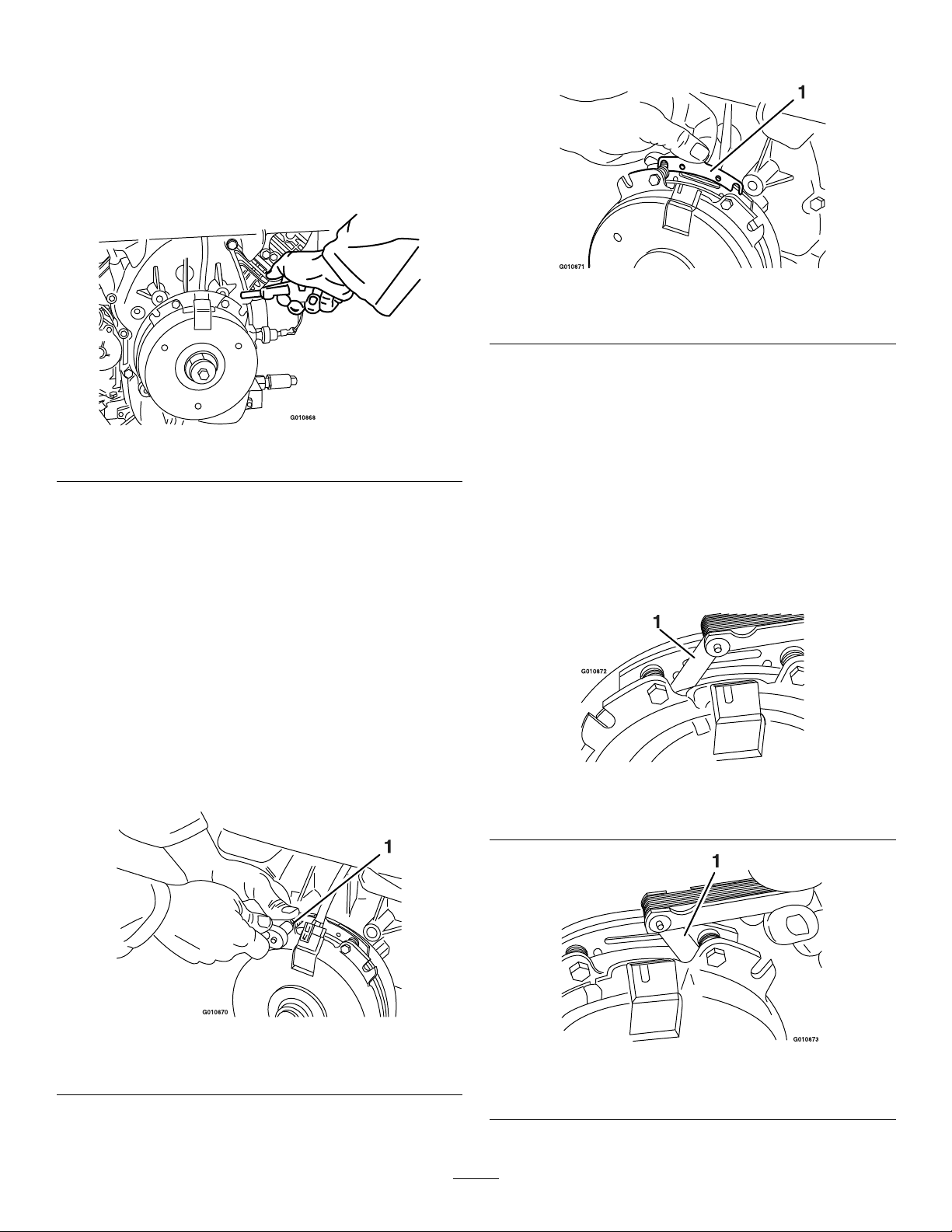
RemovingtheClutchShim
1.Stoptheengine,waitforallmovingpartsto
stop,andremovethekey.Engagetheparking
brake.Allowthemachinetocoolcompletely
beforestartingtheseinstructions.
2.Usinganaircompressor,blowoutanydebris
fromunderthebrakepoleandaroundthebrake
spacers.
Figure73
3.Checktheconditionofthewireharnessleads,
connectors,andterminals.Cleanorrepairas
necessary.
4.Verifythat12Vispresentattheclutchconnector
whenthePTOswitchisengaged.
5.Measurethegapbetweentherotorandthe
armature.Ifthegapisgreaterthan1mm(0.04
inch),proceedwiththefollowingsteps:
A.Loosenbothbrakemountingboltsone-half
toonefullturnasshownbelow.
Note:Donotdiscardtheshimuntilproper
clutchfunctionhasbeenconrmed.
g010871
Figure75
1.Shim
C.Usingapneumaticline,blowoutanydebris
fromunderthebrakepoleandaroundthe
brakespacers.
g010868
D.Re-torqueeachbolt(M6x1)to13N-m(10
ft-lb)+/-0.7N-m(0.5ft-lb).
E.Usinga0.010inchthickfeelergauge,verify
thatagapispresentbetweentherotor
andarmaturefaceonbothsidesofthe
brakepoleasshown.(Duetothewaythe
rotorandarmaturefaceswear(peaksand
valleys)itissometimesdifculttomeasure
thetruegap.)
Note:Donotremovethebrakepolefrom
theeldshell/armature.Thebrakepolehas
worntomatchthearmatureandneedsto
continuetomatchaftertheshimisremoved
toensureproperbraketorque.
Figure74
1.Brakemountingbolt
B.Usingneedle-nosepliers,orbyhand,take
holdofthetabandremovetheshim.
g010872
Figure76
1.Feelergauge
g010870
g010873
Figure77
1.Feelergauge
53
Page 54
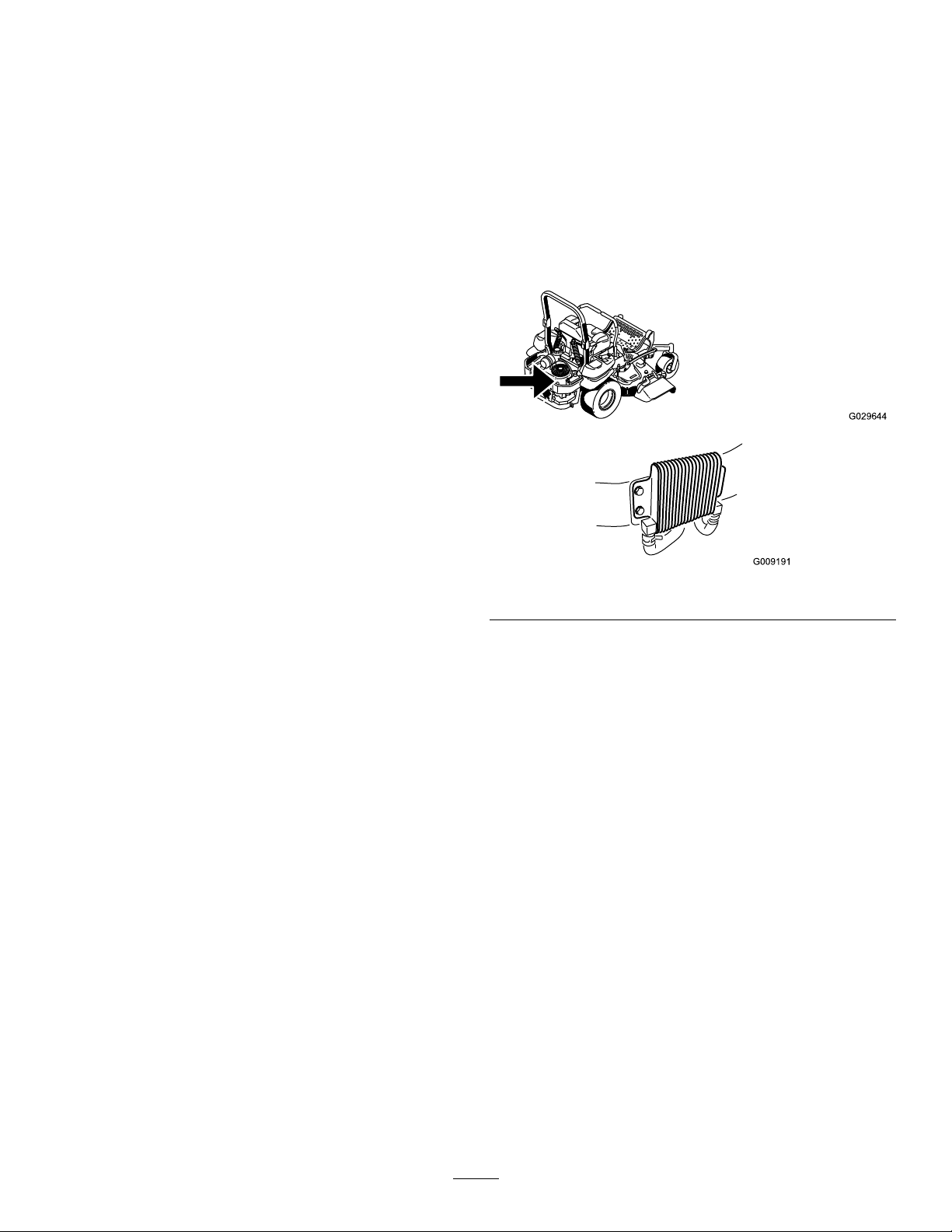
•Ifthegapislessthan0.010inch,then
reinstalltheshimandreferencethe
Troubleshootingsection.
•Ifthegapissufcient,proceedtothe
safetycheckinstepF.
F.Performthefollowingsafetycheck:
CoolingSystem
Maintenance
CleaningtheEngineScreen
i.Sitontheseatandstarttheengine.
ii.Makesurethatthebladesdonot
engagewiththePTOswitchedoff
andtheclutchdisengaged.
Iftheclutchdoesnotdisengage,
installtheshimandreferencethe
Troubleshootingsection.
iii.EngageanddisengagethePTO
switch10consecutivetimesto
ensurethattheclutchisfunctioning
properly.Iftheclutchdoesnot
engageproperly ,referencethe
Troubleshootingsection.
andEngine-OilCooler
ServiceInterval:Beforeeachuseordaily
Removeanybuildupofgrass,dirt,orotherdebris
fromtheoilcooler(Figure78).
g029644
g009191
Figure78
Beforeeachuseremoveanybuildupofgrass,dirt,or
otherdebrisfromtheenginescreen.Thiswillhelp
ensureadequatecoolingandcorrectenginespeed
andwillreducethepossibilityofoverheatingand
mechanicaldamagetotheengine(Figure79).
CleaningtheEngine CoolingFinsandShrouds
ServiceInterval:Every100hours/Y early(whichever
comesrst)
1.DisengagethePTOandsettheparkingbrake.
2.Stoptheengine,removethekey,andwait
forallmovingpartstostopbeforeleavingthe
operatingposition.
3.Removetheairintakescreen,recoilstarter,and
fanhousing(Figure79).
4.Cleanthedebrisandgrassfromtheengine
parts.
5.Installairintakescreen,recoilstarter,andfan
housing(Figure79).
54
Page 55
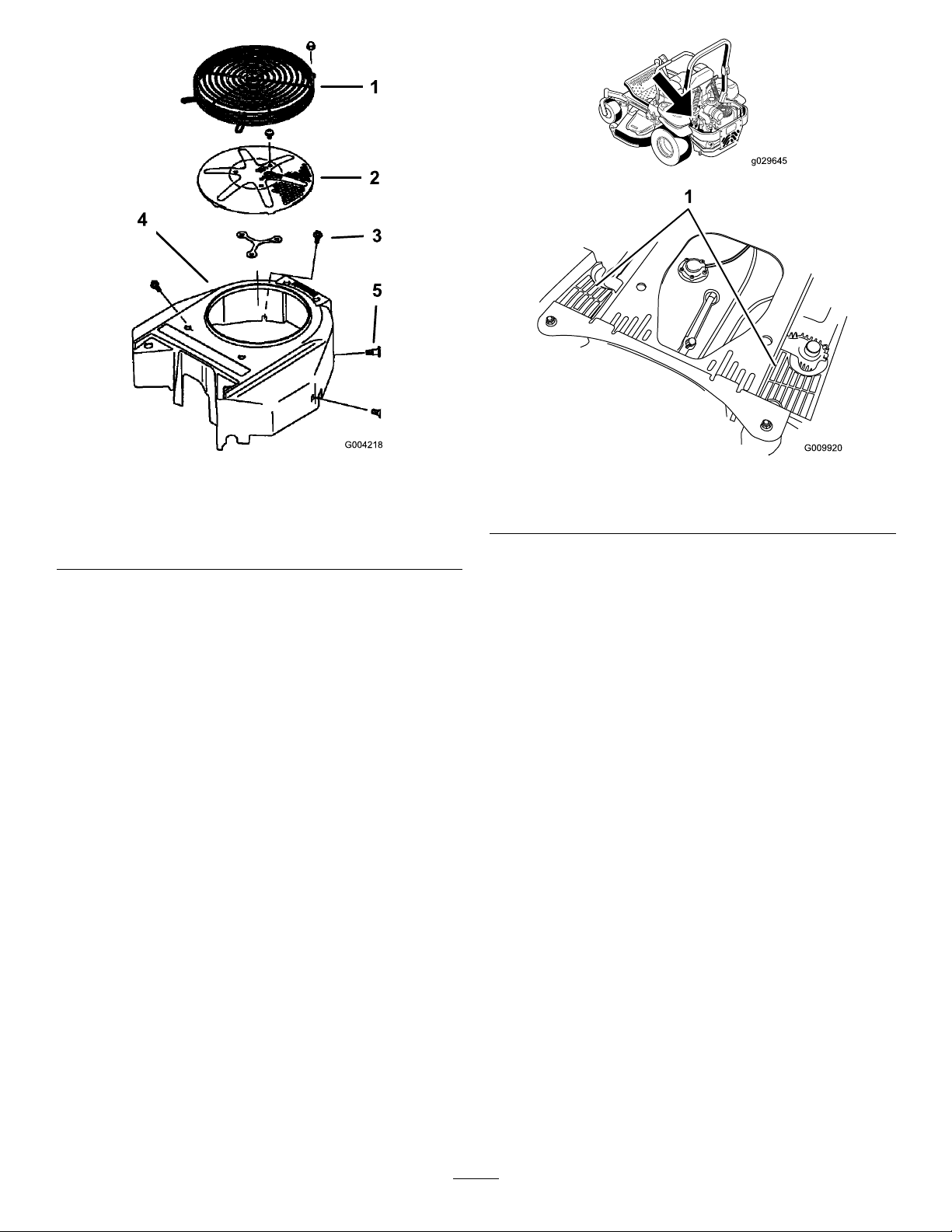
g029645
Figure79
1.Engineguard4.Fanhousing
2.Engineairintakescreen
3.Bolt
5.Screw
CheckandCleanthe Hydraulic-UnitShrouds
ServiceInterval:Beforeeachuseordaily
1.DisengagethePTOandsettheparkingbrake.
2.Stoptheengine,removethekey,andwait
forallmovingpartstostopbeforeleavingthe
operatingposition.
3.Raisetheseat.
4.Cleanthedebrisandgrassfromthehydraulic
unitshrouds(Figure80).
5.Lowertheseat.
g004218
Figure80
1.Hydraulicunitshrouds
g009920
55
Page 56
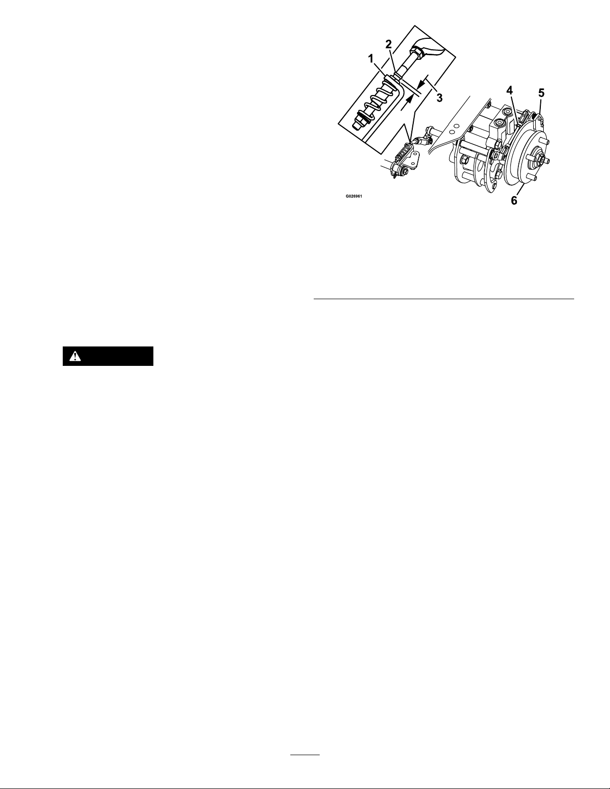
BrakeMaintenance
AdjustingtheParking Brake
ServiceInterval:Aftertherst100hours
Every500hoursthereafter
Checktomakesurethebrakeisadjustedproperly
beforeadjusting.
Note:Thisproceduremustbefollowedafterthe
rst100hoursorwhenabrakecomponenthasbeen
removedorreplaced.
1.Drivethemachineontoalevelsurface.
2.Disengagetheblade-controlswitch(PTO),move
themotion-controlleverstotheneutral-locked
positionandengagetheparkingbrake.
3.Stoptheengine,waitforallmovingpartsto
stop,andremovethekey .
4.Raisethebackofthemachineupandsupport
themachinewithjackstands.
DANGER
Mechanicalorhydraulicjacksmayfail
tosupportmachineandcauseaserious
injury.
•Usejackstandwhensupporting
machine.
•Donotusehydraulicjacks.
5.Removethereartiresfromthemachine.
6.Removeanydebrisfromthebrakearea.
7.Rotatethedrivewheelreleasehandletothe
releasedposition.RefertoUsingtheDrive
WheelReleaseV alves(page30).
8.Checktoseeifthereisavisiblegapbetween
theL-bracketandthelinkagestop(Figure81).
Figure81
LeftSideShown
1.L-bracket4.Rearlinkageassembly
2.Linkagestop
3.Gap
9.Disengagetheparkingbrake,thelevershould
beinthedownposition.
10.Turnthewheelhubbyhandinbothdirections
relativetothecaliper;thewheelhubshould
movefreelybetweenthecaliper.
11.Ifagapisneededorthewheelhubdoesnot
movefreely:
A.Disengagetheparkingbrake.
B.Disconnectandne-tunetherearlinkage
assembly:
5.Caliper
6.Wheelhub
•Shortenthelinktocreateagap.
•Lengthenthelinktoallowwheelhub
movement.
C.Reconnecttherearlinkageassembly .
12.Engagetheparkingbrakeandcheckthegap.
13.Repeatsteps9through13untilavisiblegapis
achievedandthewheelhubrotatesfreely.
14.Repeatthisprocedureforthebrakeonthe
oppositeside.
g026961
15.Rotatethedrivewheelreleasehandletothe
operatingposition.RefertoUsingtheDrive
WheelReleaseV alves(page30).
16.Installthereartiresandtorquethelugnuts.
RefertoCheckingtheWheelLugNuts(page
52).
17.Removethejackstands.
56
Page 57
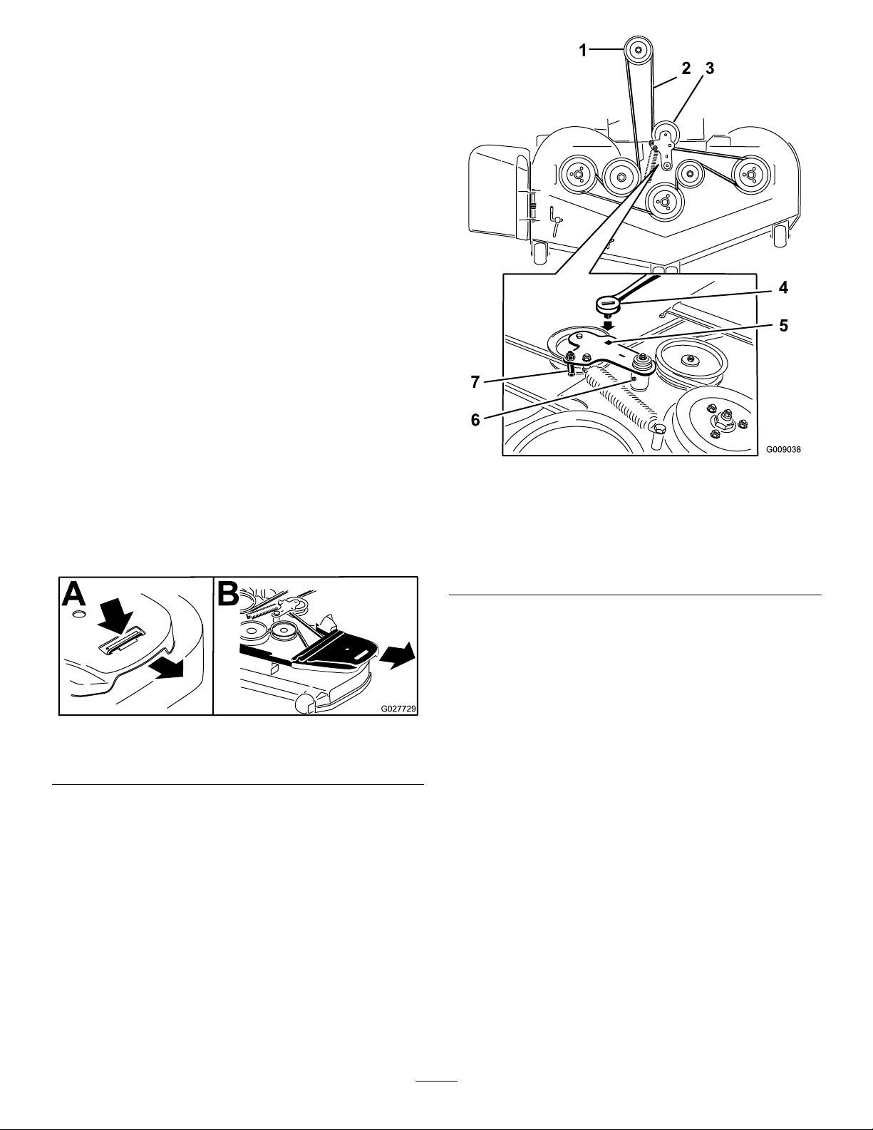
BeltMaintenance
InspectingtheBelts
ServiceInterval:Every50hours
Checkthebeltsforsquealingwhenthebeltisrotating,
bladesslippingwhencuttinggrass,frayedbeltedges,
burnmarks,andcracks.Thesearesignsofaworn
mowerbelt;replacethemowerbeltifanyofthese
conditionsareevident.
ReplacingtheMowerBelt
Squealingwhenthebeltisrotating,bladesslipping
whencuttinggrass,frayedbeltedges,burnmarks,
andcracksaresignsofawornmowerbelt.Replace
themowerbeltifanyoftheseconditionsareevident.
1.DisengagethePTO,movethemotion-control
leverstotheneutral-lockedposition,andsetthe
parkingbrake.
2.Stoptheengine,removethekey,andwait
forallmovingpartstostopbeforeleavingthe
operatingposition.
3.Lowerthemowertothe76mm(3inch)height
ofcut.
4.Removethebeltcovers(Figure82).
Figure82
1.Pushtabdown2.Removebeltcover
5.Usearatchetinthesquareholeintheidlerarm
toremovetensionontheidlerspring(Figure83).
6.Removethebeltfromthemowerdeckpulleys.
g009038
Figure83
1.Clutchpulley5.Squareholeintheidler
2.Mowerbelt
3.Spring-loadedidlerpulley
4.Ratchet
armfortheratchet
6.Idlergreasetting
7.Beltguide
10.Installthebeltguideontheidlerarmshownin
Figure83.
11.Usingtheratchetinthesquarehole,installthe
idlerspring(Figure83).
Makesurethatthespringendsareseatedin
g027729
theanchorgrooves.
12.Installthebeltcovers(Figure84).
7.Removethebeltguideonthespring-loaded
idlerarmshowninFigure83.
8.Removetheexistingbelt.
9.Installthenewbeltaroundthemowerpulleys
andtheclutchpulleyundertheengine(Figure
83).
57
Page 58
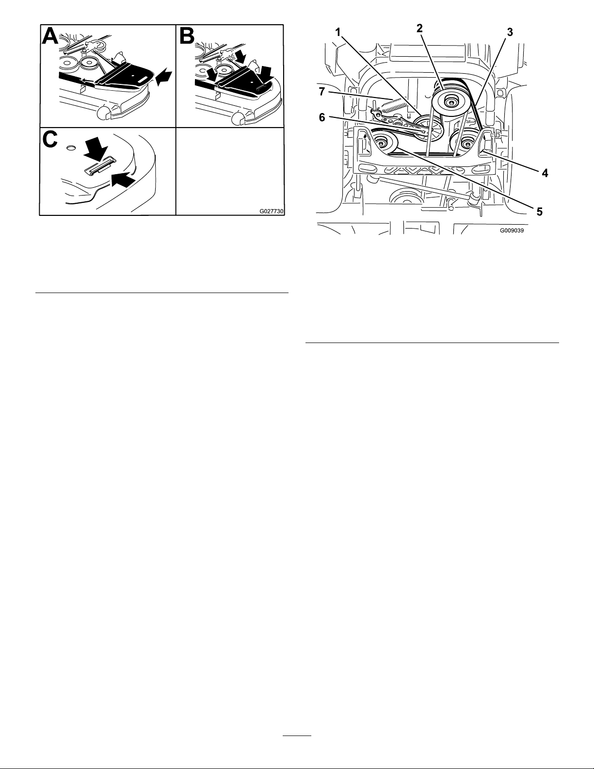
Figure84
1.Positionthebeltcover3.Ensurethatthetabis
underthemetalcatch
2.Slidebeltcoverunderthe
sidecatches
ReplacingtheHydraulic
g027730
g009039
Figure85
1.Idlerpulley
2.Clutchpulley6.Squareholeinidlerarm
3.Pumpdrivebelt7.Idlerspring
4.Right-handhydraulic
pumppulley
5.Left-handhydraulicpump
pulley
PumpDriveBelt
1.DisengagethePTOandsettheparkingbrake.
2.Stoptheengine,removethekey,andwait
forallmovingpartstostopbeforeleavingthe
operatingposition.
3.Removethemowerbelt.RefertoReplacingthe
MowerBeltinMaintenance.
4.Raisethemachineandsupportitwithjack
stands(Figure85).
5.Usearatchetinthesquareholeintheidlerarm
toremovetheidlerspring(Figure85).
6.Unhooktheidlerspringfromtheframe(Figure
85).
7.Removethebeltfromthehydraulicunitdrive
pulleysandtheenginepulley
8.Installthenewbeltaroundenginepulleyand
thetwodrivepulleys.
9.Usingaratchetinthesquareholeintheidler
arm,installtheidlerspringtotheframe(Figure
85).
10.Installthemowerbelt.RefertoReplacingthe
MowerBelt.
58
Page 59
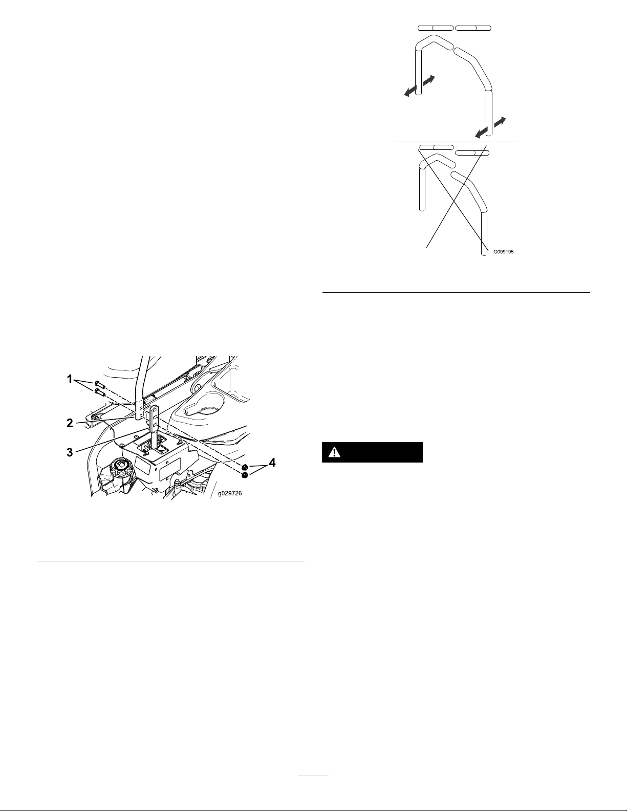
ControlsSystem
Maintenance
AdjustingtheControl HandlePosition
Thereare2heightpositionsforthecontrollevers:
highandlow.Removetheboltstoadjusttheheight
fortheoperator.
1.DisengagethePTO,movethemotion-control
leverstotheneutral-lockedposition,andsetthe
parkingbrake.
2.Stoptheengine,removethekey,andwait
forallmovingpartstostopbeforeleavingthe
operatingposition.
3.Loosentheboltsandangenutsinstalledinthe
levers(Figure86).
4.Alignthefront-to-rearpositionofthelevers
bybringingtheleverstogethertotheneutral
positionandslidingthemuntiltheyarealigned;
thentightenthebolts(Figure87).
g009195
Figure87
Adjustingthe Motion-ControlLinkage
Figure86
1.Bolt
2.Handle4.Nut
3.Controllever
Locatedoneithersideofthefueltank,belowtheseat
arethepumpcontrollinkages.Rotatingthepump
linkagewitha1/2inchwrenchallowsnetuning
adjustmentssothatthemachinedoesnotmovein
neutral.Anyadjustmentsshouldbemadeforneutral
positioningonly.
WARNING
Theenginemustberunningandthedrive
wheelsmustbeturningsothatthemotion
g029726
controladjustmentcanbeperformed.Contact
withmovingpartsorhotsurfacesmaycause
personalinjury.
Keepngers,hands,andclothingclearof
rotatingcomponentsandhotsurfaces.
1.Priortostartingtheengine,pushthedecklift
pedal,removetheheight-of-cutpin,andlower
thedecktotheground.
2.Raisetherearofthemachineupandsupportit
withjackstands(orequivalentsupport)justhigh
enoughtoallowthedrivewheelstoturnfreely.
3.Removetheelectricalconnectionfromtheseat
safetyswitch,locatedunderthebottomcushion
oftheseat.
Note:Theswitchisapartoftheseatassembly.
4.Temporarilyinstallajumperwireacrossthe
terminalsintheconnectorofthemainwiring
harness.
59
Page 60
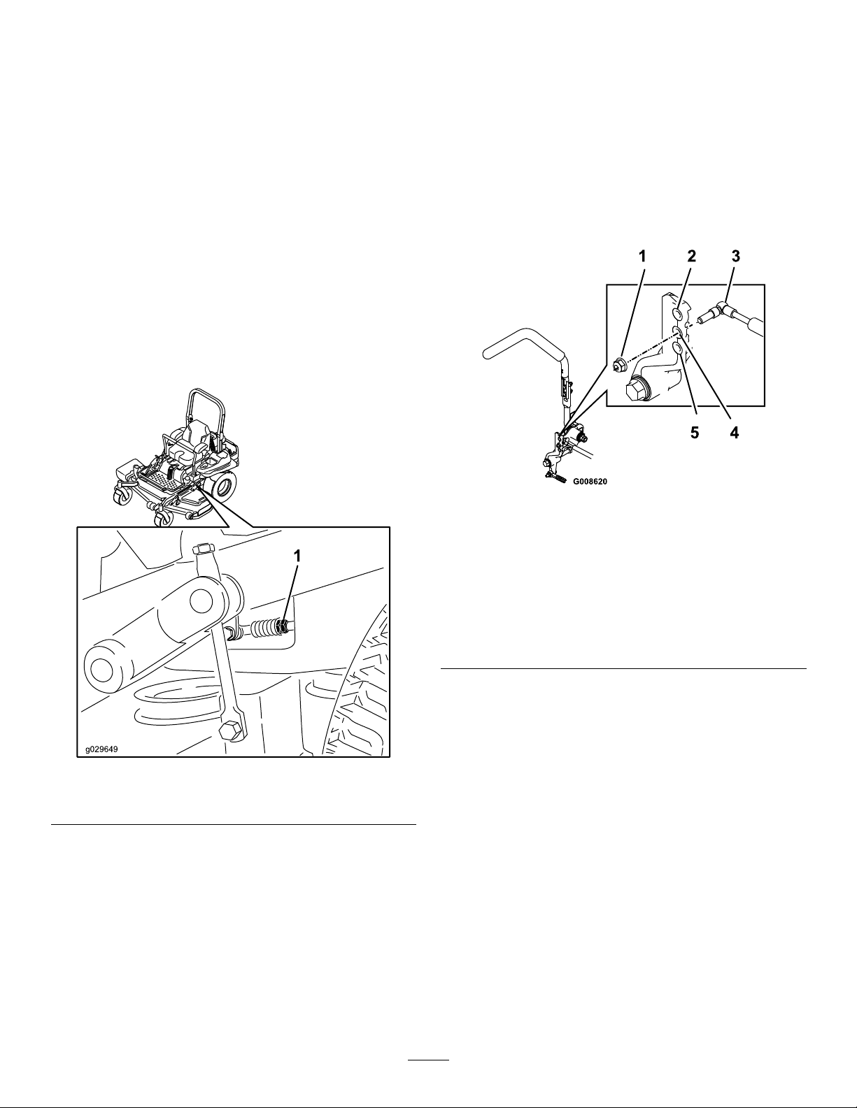
5.Starttheengine.
12.Raisethedeckandinstalltheheight-of-cutpin.
Note:Thebrakemustbeengaged,andthe
motion-controlleversout,tostarttheengine.
Theoperatordoesnothavetobeintheseat
becauseofthejumperwirebeingused.Run
theengineatfullthrottleandreleasethebrake.
6.Runthemachineatleast5minuteswiththe
driveleversatfullforwardspeedtobring
hydraulicoiluptooperatingtemperature.
Note:Themotion-controlleverneedsto
beinneutralwhilemakinganynecessary
adjustments.
7.Bringthemotion-controlleversintotheneutral
position.
8.Adjustthepumpcontrolrodlengthsbyrotating
thedoublenutsontherodintheappropriate
directionuntilthewheelsslightlycreepin
reverse(Figure88).
13.Checkthatthemachinedoesnotcreepin
neutralwiththeparkingbrakedisengaged.
Adjustingthe Motion-ControlDamper
Thetopdampermountingboltcanbeadjustedto
obtainamoredesiredmotion-controlleverresistance.
SeeFigure89formountingoptions.
Figure88
1.Doublenuts
9.Movethemotion-controlleverstothereverse
positionandwhileapplyingslightpressureto
theleverallowthereverseindicatorspringsto
bringtheleversbacktoneutral.
Note:Thewheelsmuststopturningorslightly
creepinreverse.
10.Stoptheengine,removethejumperwirefrom
thewireharness,andplugtheconnectorinto
theseatswitch.
11.Removethejackstands.
g008620
Figure89
Right-handmotioncontrolshown
1.T orquethelocknutto23N-m(17ft-lb).Theboltmust
protrudepasttheendofthelocknutaftertorquing.
2.Mostresistance(rmestfeel)
3.Damper
4.Mediumresistance(mediumfeel)
5.Leastresistance(softestfeel)
Adjustingthe
Motion-ControlNeutral
g029649
LockPivot
Theangednutcanbeadjustedtoobtainamore
desiredmotion-controlleverresistancewhenmoving
ittotheneutrallockposition.SeeFigure90for
adjustmentoptions.
1.Loosenthejamnut.
2.Tightenorloosentheangednuttothedesired
feel.
Formoreresistance,tightentheangednut.
Forlessresistance,loosentheangednut
3.Tightenthejamnut.
60
Page 61

HydraulicSystem
Maintenance
ServicingtheHydraulic System
Figure90
1.Flangednut2.Jamnut
g008621
HydraulicOilType:T oro
oilorMobil
®
115W-50.
®
HYPR-OIL
™
500hydraulic
Important:Useoilspecied.Otheruidscould
causesystemdamage.
EachHydraulicSystemOilCapacity:1.5L(1.59
USqt)persidewithlterchange
CheckingtheHydraulicOil
ServiceInterval:Every50hours—Checkthe
hydraulicoillevel.
1.Positionthemachineonalevelsurface.
2.DisengagethePTO,movethemotion-control
leverstotheneutral-lockedpositionandsetthe
parkingbrake.
3.Stoptheengine,removethekey,andwait
forallmovingpartstostopbeforeleavingthe
operatingposition.
4.Allowtheengineandthehydraulicsystemto
coolfor10minutes.
Note:Theoillevelonthedipstickwillbe
incorrectiftheoilischeckedwhenthemachine
ishot.
5.Movetheseatforward.
6.Cleantheareaaroundthedipsticksofthe
hydraulic-systemreservoirs(Figure91).
7.Removeonedipstickfromthehydraulicreservoir
(Figure91).
8.Wipethedipstickoffandthreadthedipstickinto
thereservoir.
9.Removethedipstickandlookattheend(Figure
91).Iftheoillevelisattheaddmark,slowly
pouronlyenoughoilintothehydraulicreservoir
toraisetheleveltothefullorHline.
Important:Donotoverllthehydraulic
unitswithoilasdamagemayoccur.Donot
runthemachinewiththeoilbelowtheadd
mark.
10.Installthedipstick.
11.Repeatprocedurefortheoppositedipstick.
61
Page 62
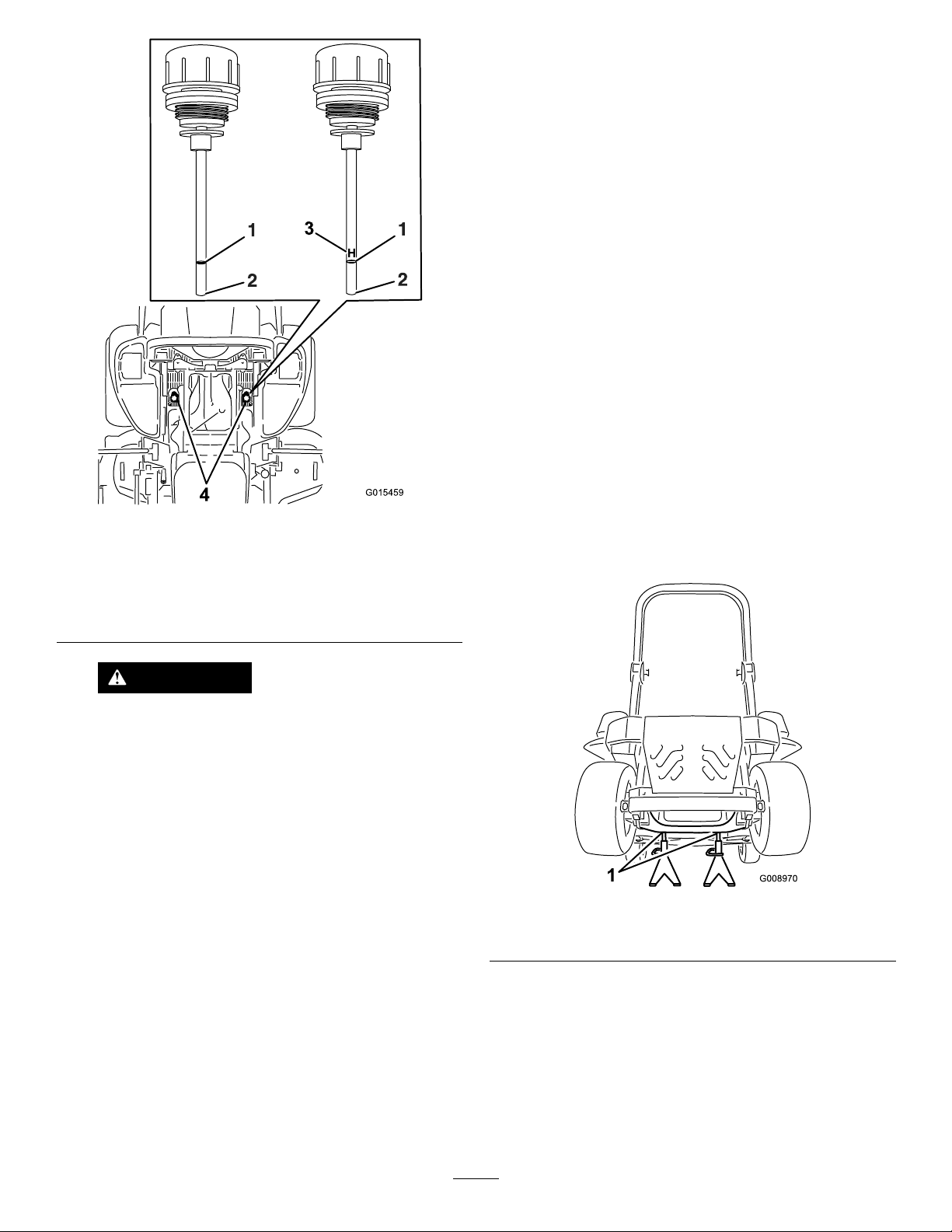
ReplacingtheHydraulicFilters andHydraulicOil
ServiceInterval:Aftertherst250hours—Change
thehydraulicltersandhydraulicoil
whenusinganytypeofoil.
Figure91
Eitherdipstickwillbeusedinthemachine
1.Full3.H—meanshighlevel
2.Add4.Dipsticklocationsunder
seat
Every250hours—Changethehydrauliclters
andhydraulicoilwhenusingMobil
®
1oil(more
oftenindirtyordustyconditions).
Every500hours—Changethehydrauliclters
andhydraulicoilwhenusingT oro
®
HYPR-OIL
™
500hydraulicoil(moreoftenindirtyordusty
conditions).
Toreplacethehydraulicoil,theltersneedtobe
removed.Replacebothatthesametime.Referto
theoilspecicationsunderServicingtheHydraulic
System(page61)forthecorrectoil.
1.Disengagetheblade-controlswitch(PTO),move
themotion-controlleverstotheneutral-locked
positionandsettheparkingbrake.
2.Stoptheengine,removethekey,andwait
forallmovingpartstostopbeforeleavingthe
g015459
operatingposition.
3.Raisethemachineandsupportitwithjack
stands(Figure92).
WARNING
Hydraulicoilescapingunderpressure
canpenetrateskinandcauseinjury .
•Ifhydraulicoilisinjectedintotheskin
itmustbesurgicallyremovedwithin
afewhoursbyadoctorfamiliarwith
thistypeofinjury.Gangrenemay
resultifthisisnotdone.
•Keepbodyandhandsawayfrompin
holeleaksornozzlesthatejecthigh
pressurehydraulicoil.
•Usecardboardorpapertond
hydraulicleaks.
•Safelyrelieveallpressureinthe
hydraulicsystembeforeperforming
anyworkonthehydraulicsystem.
•Makesureallhydraulicoilhosesand
linesareingoodconditionandall
hydraulicconnectionsandttings
aretightbeforeapplyingpressureto
hydraulicsystem.
g008970
Figure92
1.Jackstands
4.Removeboththemowerbeltandthepump
drivebelt.Thiswillpreventoilgettingonthe
belts.RefertoBeltMaintenance(page57).
5.Placeadrainpanunderthelter,removethe
oldlterandwipethesurfaceclean(Figure93).
62
Page 63
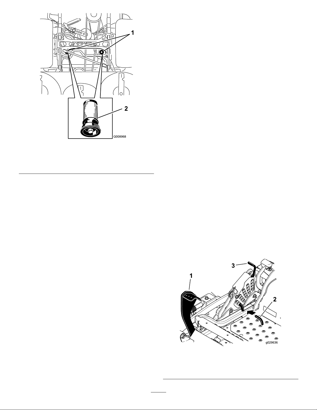
MowerDeck Maintenance
LevelingtheMowerDeck
SettingUptheMachine
Note:Ensurethatthemowerdeckisleveledbefore
matchingtheheightofcut(HOC).
1.Positionthemachineonaatsurface.
2.Disengagetheblade-controlswitch(PTO),move
themotion-controlleverstotheneutral-locked
positionandsettheparkingbrake.
3.Stoptheengine,removethekey,andwait
forallmovingpartstostopbeforeleavingthe
operatingposition.
g008968
Figure93
BottomViewofMachine
1.Filterlocations
2.Hydrauliclter
4.Checkthetirepressureofthedrivetires.If
needed,adjustthepressureto90kPa(13psi)
5.Positionthemowertothe76mm(3inch)
height-of-cutposition.
6.Applyathincoatofhydraulicoiltotherubber
gasketonthereplacementlter(Figure93).
7.Installthereplacementhydrauliclter.
8.Installthepumpdrivebeltandthemowerbelt.
9.Removethejackstandsandlowerthemachine
(Figure92).
10.Addoiltothehydraulicreservoirandcheckfor
anyleaks.
11.Cleanupanyspilledoil.
12.Starttheengineandletitrunforabouttwo
minutestopurgeairfromthesystem.Stopthe
engineandcheckforleaks.
13.Checktheoillevelwhiletheoiliscold.
14.Ifrequired,addoiltothehydraulicreservoir.Do
notoverll.
LevelingtheDeck
1.Positionthemoweronaatsurface.
2.Stopengine,waitforallmovingpartstostop,
andremovekey.Engageparkingbrake.
3.Checkthetirepressureinthedrivetires.Proper
inationpressurefortiresis90kPa(13psi).
Adjustifnecessary.
4.Positionthetransportlockinthelatching
position.
5.Pushthedeckliftpedalallthewayforwardand
thedeckwilllatchatthe14cm(5-1/2inch)
transportposition(Figure94).
1.Deck-liftpedal
2.Height-of-cutpin
63
g029840
Figure94
3.Transportlock
Page 64
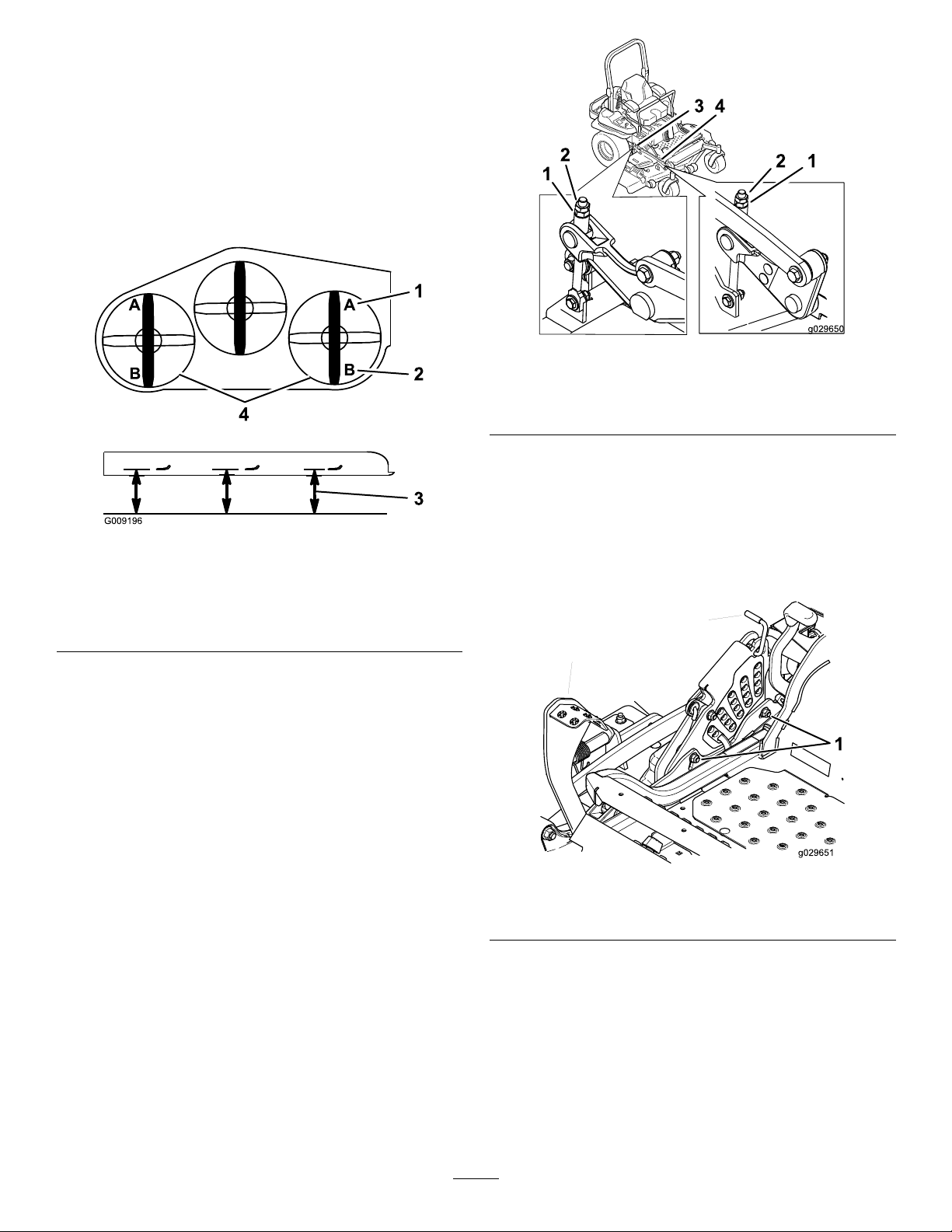
6.Inserttheheight-adjustmentpinintothe7.6cm
(3inch)cutting-heightposition.
7.Releasethetransportlockandallowthedeckto
lowertothecuttingheight.
8.Raisethedischargechute.
9.Onbothsidesofthedeck,measurefromthe
levelsurfacetothefronttipoftheblade(Postion
A).Themeasurementshouldread7.6mm(3
inches);refertoFigure95.
Figure95
1.7.6cm(3inches)atAis
correct
2.8.3cm(3-1/4inches)atB
iscorrect
3.Measureherefromthe
bladetiptohardsurface
4.MeasureatAandBon
bothsides
g029650
Figure96
1.Flangedlocknut3.Jamnut
2.Adjusterscrew4.Y oke
11.Ifthefrontdecklinksdonothaveenough
adjustmenttoachieveaccuratecutheight,the
singlepointadjustmentcanbeutilizedtogain
moreadjustment.
g009196
12.T oadjustthesinglepointsystem,loosenthetwo
boltsatthebottomoftheheight-of-cutplate.
RefertoFigure97.
10.Ifneeded,loosentheangedlocknutontheside
oftheyokeandthejamnutontop.Fine-tune
theadjusterscrewbyturningittoget7.6mm(3
inch)height(Figure96).
Toincreasetheheight,turntheadjusterscrew
clockwise;todecreasetheheight,turnit
counterclockwise.
g029651
Figure97
1.Boltsatthebottomoftheheight-of-cutplate
13.Ifthedeckistoolow,tightenthesinglepoint
adjustmentboltbyrotatingitclockwise.If
thedeckistoohigh,loosenthesinglepoint
adjustmentboltbyrotatingitcounterclockwise
(Figure98).
Note:Loosenortightenthesinglepoint
adjustmentboltenoughtomovethe
height-of-cutplatemountingboltsatleast1/3
thelengthoftheavailabletravelintheirslots.
64
Page 65
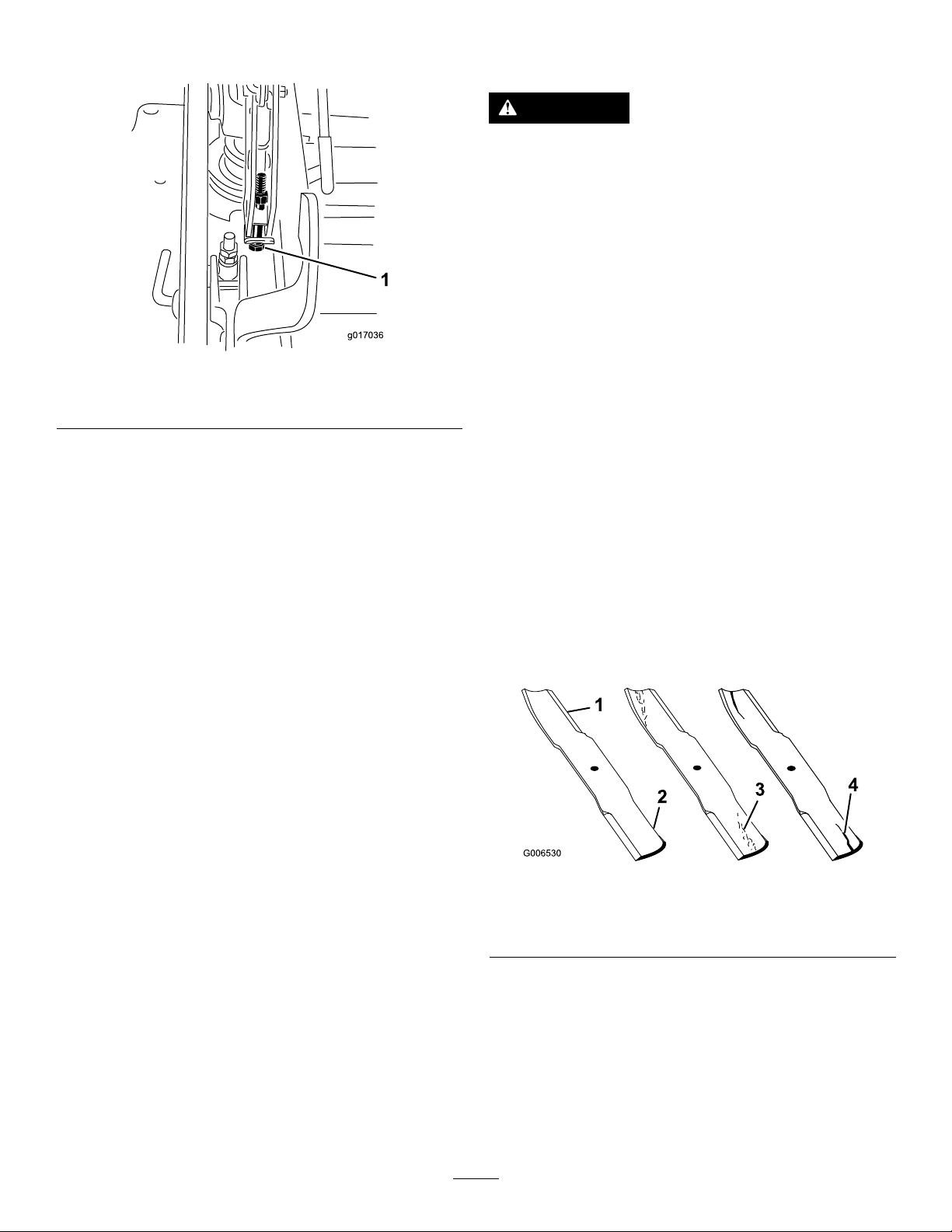
Thiswillregainsomeup-and-downadjustment
oneachofthe4decklinks.
sharpeningandreplacement,youmaywanttokeep
extrabladesonhand.
DANGER
Awornordamagedbladecanbreak,anda
pieceofthebladecouldbethrownintothe
operator'sorbystander'sarea,resultingin
seriouspersonalinjuryordeath.
•Inspectthebladeperiodicallyforwearor
damage.
•Replaceawornordamagedblade.
BeforeInspectingorServicingthe
Figure98
1.Singlepointadjustmentbolt
14.Tightenthe2boltsatthebottomofthe
height-of-cutplate(Figure97).T orquethemto
37to45N-m(27to33ft-lb).
Note:Inmostconditions,thebackbladetip
shouldbeadjusted6.4mm(1/4inch)higher
thanthefront.
15.Onbothsidesofthedeck,measurefromthe
levelsurfacetothebacktipoftheblade(Postion
B).Themeasurementshouldread8.3cm(3-1/4
inches);refertoFigure95.
16.Fine-tunetheadjusterscrewbyturningittoget
8.3mm(3-1/4inches)height(Figure96).
Toincreasetheheight,turntheadjustmentnut
clockwise;todecreasetheheight,turnthenut
counterclockwise.
17.Measureuntilall4sidesarethecorrectheight.
Tightenallthejamnutsonthedeck-liftarm
assemblies.
18.Lowerthedischargechute.
g017036
Blades
Parkthemachineonalevelsurface,disengagethe
blade-controlswitch(PTO),andsettheparkingbrake.
TurntheignitionkeytoOff.Removethekey.
InspectingtheBlades
ServiceInterval:Beforeeachuseordaily
1.Inspectthecuttingedges(Figure99).Ifthe
edgesarenotsharporhavenicks,removeand
sharpentheblades.RefertoSharpeningthe
Blades.
2.Inspecttheblades,especiallythecurvedarea
(Figure99).Ifyounoticeanydamage,wear,ora
slotforminginthisarea(Figure99),immediately
installanewblade.
ServicingtheCutting Blades
Maintainsharpbladesthroughoutthecuttingseason,
becausesharpbladescutcleanlywithouttearingor
shreddingthegrassblades.T earingandshredding
turnsgrassbrownattheedges,whichslowsgrowth
andincreasesthechanceofdisease.
Checkthecutterbladesdailyforsharpness,and
foranywearordamage.Filedownanynicksand
sharpenthebladesasnecessary.Ifabladeis
damagedorworn,replaceitimmediatelywitha
genuineTororeplacementblade.Forconvenient
g006530
Figure99
1.Cuttingedge3.Wear/slotforming
2.Curvedarea4.Crack
CheckingforBentBlades
1.Disengagetheblade-controlswitch(PTO),move
themotion-controlleverstotheneutral-locked
positionandsettheparkingbrake.
2.Stoptheengine,removethekey,andwait
forallmovingpartstostopbeforeleavingthe
operatingposition.
65
Page 66
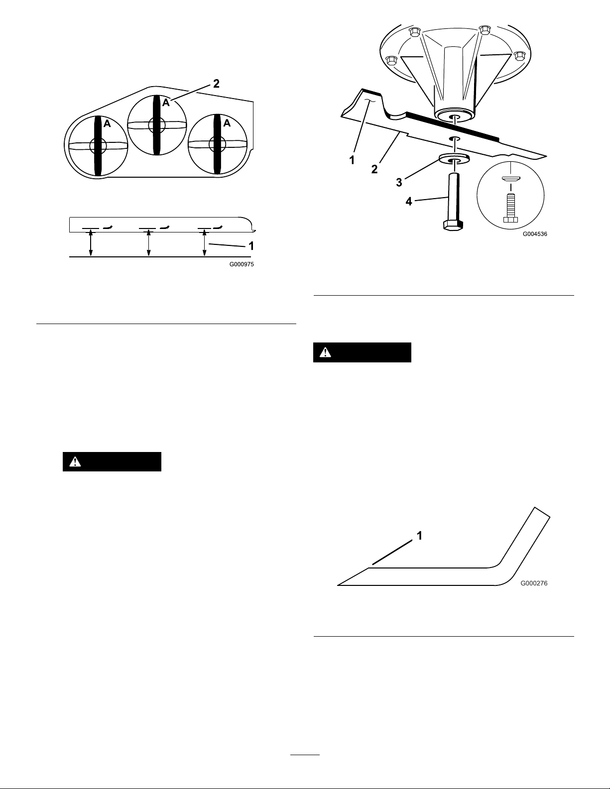
3.Rotatethebladesuntiltheendsfaceforward
andbackward(Figure100).Measurefroma
levelsurfacetothecuttingedge,positionA,of
theblades(Figure100).Notethisdimension.
g004536
Figure101
Figure100
1.Measureherefromblade
tohardsurface
2.PositionA
4.Rotatetheoppositeendsofthebladesforward.
5.Measurefromalevelsurfacetothecuttingedge
ofthebladesatthesamepositionasinstep3
above.Thedifferencebetweenthedimensions
obtainedinsteps3and4mustnotexceed
1/8inch(3mm).Ifthisdimensionexceeds
1/8inch(3mm),thebladeisbentandmust
bereplaced;refertoRemovingtheBladesand
InstallingtheBlades.
WARNING
Abladethatisbentordamagedcould
breakapartandcouldseriouslyinjureor
killyouorbystanders.
•Alwaysreplacebentordamaged
bladewithanewblade.
•Neverleorcreatesharpnotchesin
theedgesorsurfacesofblade.
g000975
1.Sailareaofblade3.Curvedwasher
2.Blade4.Bladebolt
SharpeningtheBlades
WARNING
Whensharpeningblades,piecesofablade
couldbethrownandcauseseriousinjury.
Wearpropereyeprotectionwhensharpening
blades.
1.Usealetosharpenthecuttingedgeatboth
endsoftheblade(Figure102).Maintainthe
originalangle.Thebladeretainsitsbalanceif
thesameamountofmaterialisremovedfrom
bothcuttingedges.
RemovingtheBlades
Bladesmustbereplacedifasolidobjectishit,ifthe
bladeisoutofbalanceorisbent.T oensureoptimum
performanceandcontinuedsafetyconformanceof
themachine,usegenuineTororeplacementblades.
Replacementbladesmadebyothermanufacturers
mayresultinnon-conformancewithsafetystandards.
1.Holdthebladeendusingaragorthickly-padded
glove.
2.Removethebladebolt,curvedwasher,and
bladefromthespindleshaft(Figure101).
g000276
Figure102
1.Sharpenatoriginalangle
2.Checkthebalanceofthebladebyputtingitona
bladebalancer(Figure103).Ifthebladestays
inahorizontalposition,thebladeisbalanced
andcanbeused.Ifthebladeisnotbalanced,
lesomemetalofftheendofthesailareaonly
(Figure104).Repeatthisprocedureuntilthe
bladeisbalanced.
66
Page 67

InstallingtheBlades
1.Installthebladeontothespindleshaft(Figure
104).
Figure103
1.Blade2.Balancer
g000277
Important:Thecurvedpartoftheblade
mustbepointingupwardtowardtheinside
ofthemowertoensurepropercutting.
2.Installthespringdiskandthebladebolt.The
springdiskconemustbeinstalledtowardthe
bolthead(Figure104).T orquethebladeboltto
115to150N-m(85to110ft-lb).
67
Page 68
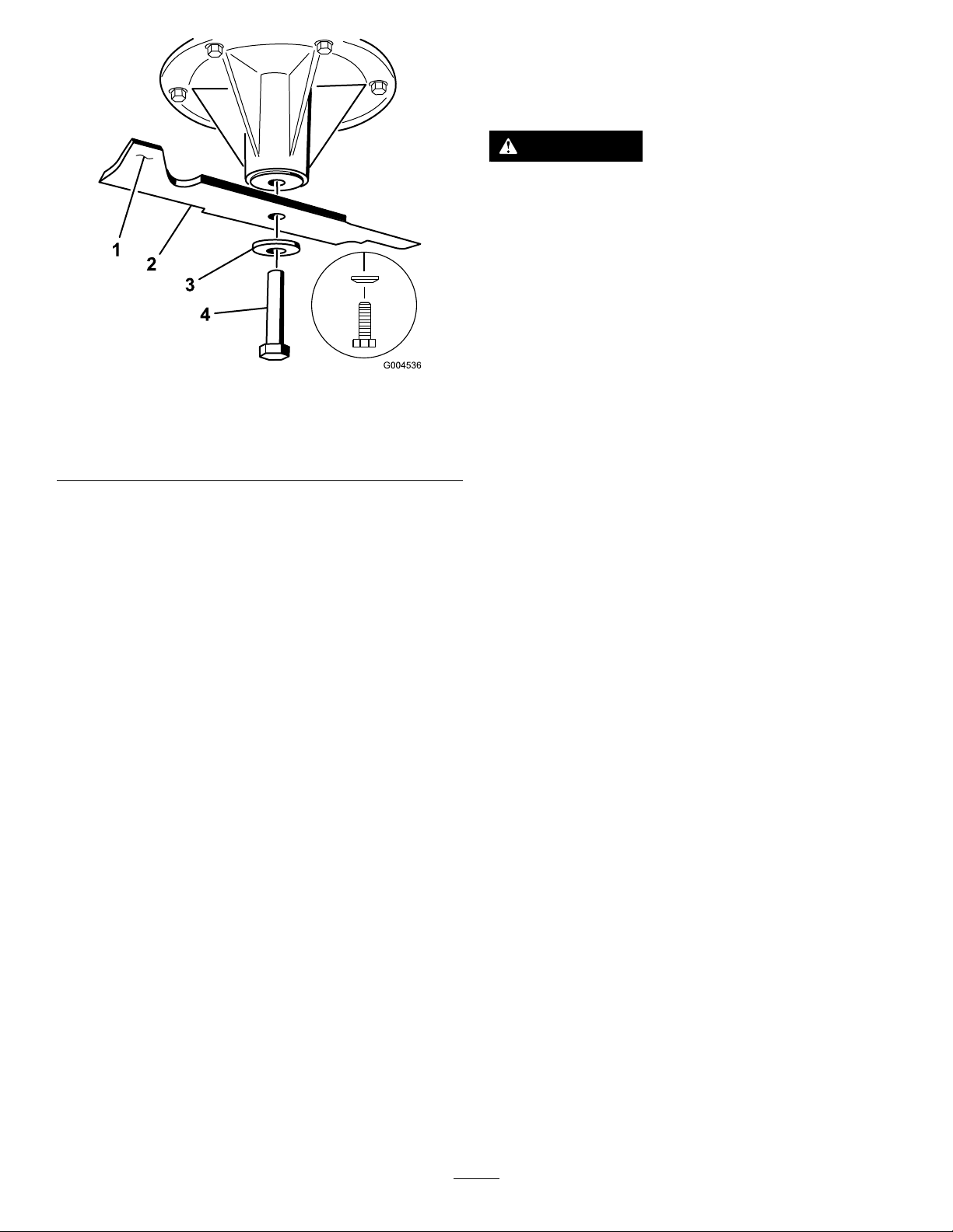
1.Sailareaofblade
2.Blade
3.Curvedwasher
Figure104
4.Bladebolt
5.Conetowardsbolthead
RemovingtheMowerDeck
Beforeservicingorremovingthemowerdeck,the
spring-loadeddeckarmsmustbelockedout.
WARNING
Deckliftarmassemblieshavestoredenergy.
Removingthedeckwithoutreleasingthe
storedenergycancauseseriousinjuryor
death.
Donotattempttodisassemblethedeckfrom
thefrontframewithoutlockingoutthestored
energy.
1.Stoptheengine,waitforallmovingpartstostop,
g004536
andremovethekey.Engagetheparkingbrake.
2.Removetheheight-adjustmentpinandlower
thedecktotheground.
3.Placetheheight-adjustmentpininthe7.6cm(3
inch)cutting-heightlocation.
Note:Thislocksthedeckliftarmsinthelowest
positionwhenthedeckisremovedandthe
storedenergyinthedeckspringisreleased.
4.Removethebeltcovers.
5.Liftuptheoorpanandinsertaratchetintothe
squareholeinthedeckidler(Figure105).
6.Rotatethedeckidlerclockwiseandremovethe
mowerbelt(Figure105).
68
Page 69
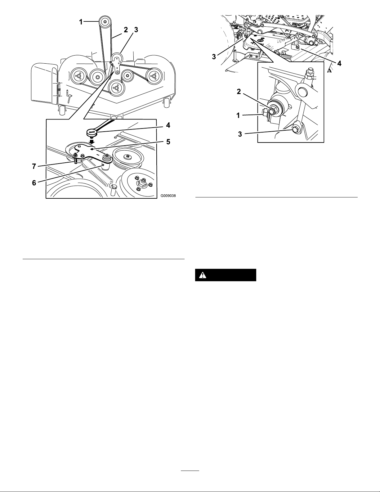
Figure105
1.Clutchpulley5.Squareholeintheidler
2.Mowerbelt
3.Spring-loadedidlerpulley
4.Ratchet
armfortheratchet
6.Idlergreasetting
7.Beltguide
7.Removeandretainthehardwareonbothsides
ofthedeckasshowninFigure106.
g029652
Figure106
1.Rightstabilizer
2.Deckstrut(rightsideshown)
3.Removethereardeckliftattachmentshoulderboltandnut.
4.Removethefrontdeckliftattachmentshoulderboltandnut.
g009038
8.Raisethedeckstrutsandsecurethemintheup
position.Slidethedeckouttotherightsideof
themachine.
ReplacingtheGrass
Deector
WARNING
Operatingthemachinewiththeengine
runningataspeedgreaterthanthefactory
settingcancausethemachinetothrowapart
ofthebladeorenginetowardtheoperatoror
abystanderandresultinseriouspersonal
injuryordeath.
Neveroperatethemachineunlessyouinstall
acoverplate,amulchplate,agrassdeector,
orabagger.
1.Removethelocknut,bolt,spring,andspacer
holdingthedeectortothepivotbrackets
(Figure107).Removethedamagedorworn
grassdeector.
69
Page 70
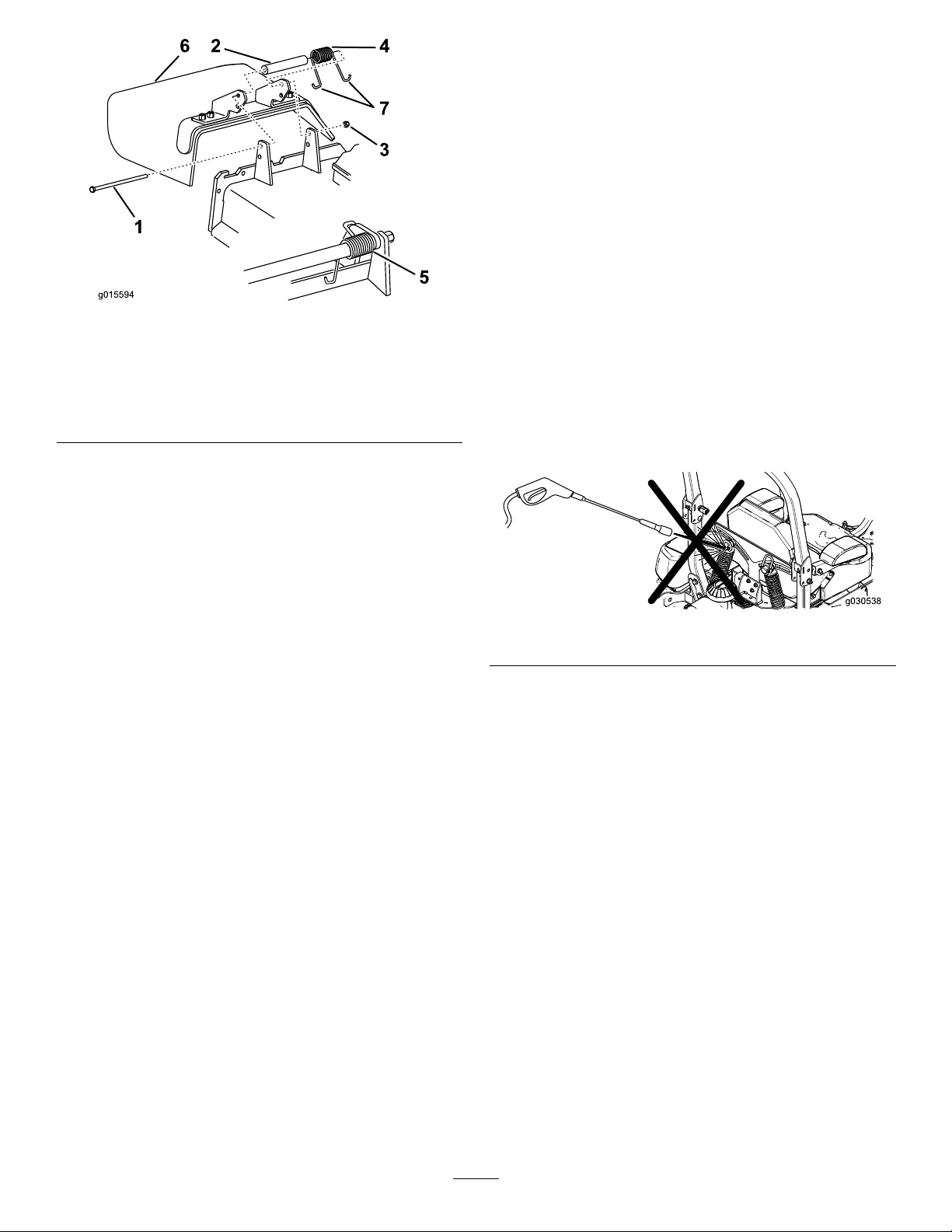
Figure107
Cleaning
CleaningundertheMower
ServiceInterval:Beforeeachuseordaily
1.Disengagetheblade-controlswitch(PTO),move
themotion-controlleverstotheneutral-locked
positionandsettheparkingbrake.
2.Stoptheengine,removethekey,andwait
forallmovingpartstostopbeforeleavingthe
operatingposition.
g015594
3.Raisethemowertothetransportposition.
1.Bolt
2.Spacer6.Grassdeector
3.Locknut
4.Spring
2.Placethespacerandthespringontothegrass
deector.PlaceoneJendofthespringbehind
thedeckedge.
5.Springinstalled
7.J-hookendofspring
Note:MakesureoneJ-endofthespringis
installedbehindthedeckedgebeforeinstalling
theboltasshowninFigure107.
3.Installtheboltandthenut.PlaceoneJ-hook
endofthespringaroundthegrassdeector
(Figure107).
Important:Thegrassdeectormustbeable
torotate.Liftthedeectoruptothefullopen
positionandensurethatitrotatesintothe
fulldownposition.
CleaningtheSuspension System
Note:Donotcleantheshockassemblieswith
pressurizedwater.
g030538
Figure108
DisposingofWaste
Engineoil,batteries,hydraulicoil,andenginecoolant
arepollutantstotheenvironment.Disposeofthese
accordingtoyourstateandlocalregulations.
70
Page 71

Storage
CleaningandStorage
1.Disengagethepowertakeoff(blade-control
switch(PTO),settheparkingbrake,andturn
theignitionkeytoOff.Removethekey.
2.Removegrassclippings,dirt,andgrimefromthe
externalpartsoftheentiremachine,especially
theengineandhydraulicsystem.Cleandirtand
chafffromtheoutsideoftheenginecylinder
headnsandblowerhousing.
Important:Youcanwashthemachinewith
milddetergentandwater.Donotpressure
washthemachine.Avoidexcessiveuse
ofwater,especiallynearthecontrolpanel,
engine,hydraulicpumps,andmotors.
3.Checkthebrake;refertoBrakeMaintenance
(page56).
4.Servicetheaircleaner;refertoServicingtheAir
Cleaner(page39).
B.Runtheenginetodistributeconditionedfuel
throughthefuelsystem(5minutes).
C.Stoptheengine,allowittocool,anddrain
thefueltank;refertoServicingtheFuel
Tank(page46).
D.Restarttheengineandrunituntilitstops.
E.Disposeoffuelproperly.Recycleasper
localcodes.
Important:Donotstore
stabilizer/conditionedfuelover
90days.
13.Checkandtightenallbolts,nuts,andscrews.
Repairorreplaceanypartthatisdamaged.
14.Paintallscratchedorbaremetalsurfaces.Paint
isavailablefromyourAuthorizedServiceDealer.
15.Storethemachineinaclean,drygarageor
storagearea.Removethekeyfromtheignition
switchandkeepitoutofreachofchildrenor
otherunauthorizedusers.Coverthemachineto
protectitandkeepitclean.
5.Greasethemachine;refertoLubrication(page
36)
6.Changethecrankcaseoil;refertoChangingthe
EngineOil(page41).
7.Checkthetirepressure;refertoCheckingthe
TirePressure(page51).
8.Changethehydrauliclters;refertoServicing
theHydraulicSystem(page61).
9.Chargethebattery;refertoChargingtheBattery
(page48).
10.Scrapeanyheavybuildupofgrassanddirt
fromtheundersideofthemower,thenwashthe
mowerwithagardenhose.
Note:Runthemachinewiththeblade-control
switch(PTO)engagedandtheengineathigh
idlefor2to5minutesafterwashing.
11.Checktheconditionoftheblades;referto
ServicingtheCuttingBlades(page65).
12.Forstorageover30days,preparethemachine
asfollows:
A.Addapetroleum-based
stabilizer/conditionertofuelinthe
tank.Followthemixinginstructionsfrom
thestabilizermanufacturer.Donotuse
analcohol-basedstabilizer(ethanolor
methanol).
Note:Afuelstabilizer/conditionerismost
effectivewhenmixedwithfreshfueland
usedatalltimes.
71
Page 72

Troubleshooting
Problem
ThemalfunctionIndicatorLight(MIL)
comeson.
Thestarterdoesnotcrank.
PossibleCauseCorrectiveAction
1.Theengineistoohot.
2.Thereisoldgasinthegastank.2.Usenewgas.
3.Thefuelshut-offvalveisnotopen
completely.
4.Theaircleanerisdirty.4.Makesurethattheaircleanerand
5.Thebatteryisnotcharged.
6.Incorrectfuelltersarebeingusedor
thefuelltersaredirty.
7.Theconnectionstothesensors
electroniccontrolunit(ECU)andfuel
injectorsarenotsecuredproperly .
8.Thereislowvoltagefromthebattery.
9.Afuseisblown.9.Checkandreplaceanyblownfuses.
1.Theblade-controlswitch(PTO)is
engaged.
2.Theparkingbrakeisnoton.
3.Themotion-controlleversarenotin
theneutral-lockposition.
4.Theoperatorisnotseated.
5.Thebatteryisdead.
6.Theelectricalconnectionsare
corrodedorloose.
7.Thefuseisblown.7.Replacethefuse.
8.Therelayorswitchiswornor
damaged.
1.Turntheengineoffandletitcool.
3.Openthefuelshut-offvalve.
precleanerareclean.Replaceif
necessary.
5.Chargeorreplacethebattery.
6.ContactanAuthorizedServiceDealer.
7.ContactanAuthorizedServiceDealer.
8.Ensureagood12voltbatteryisbeing
usedandisfullycharged.
1.Movetheblade-controlswitch(PTO)
tothedisengagedposition.
2.Settheparkingbrake.
3.Ensurethatthemotion-controllevers
areintheneutral-lockposition.
4.Sitontheseat.
5.Chargethebattery.
6.Checktheelectricalconnectionsfor
goodcontact.
8.ContactanAuthorizedServiceDealer.
Theenginedoesnotstart,startshard,or
failstokeeprunning.
1.Thefueltankisempty.1.Fillthefueltank.
2.Thefuel-shutoffvalveisclosed.2.Openthefuel-shutoffvalve.
3.Theoillevelinthecrankcaseislow.3.Addoiltothecrankcase.
4.Thethrottleisnotinthecorrect
position.
5.Thereisdirtinthefuellter.5.Replacethefuellter.
6.Thereisdirt,water,orstalefuelisin
thefuelsystem.
7.Theaircleanerisdirty.
8.Theseatswitchisnotfunctioning
properly.
9.Theelectricalconnectionsare
corroded,loose,ordamaged.
10.Therelayorswitchiswornor
damaged.
11.Thesparkplugisfouledorimproperly
gapped.
12.Thespark-plugwireisnotconnected.
4.Besurethatthethrottlecontrolis
midwaybetweentheslowandfast
positions.
6.ContactanAuthorizedServiceDealer.
7.Cleanorreplacetheair-cleaner
element.
8.Checktheseat-switchindicator.
Replacetheseatifnecessary .
9.Checktheelectricalconnections
forgoodcontact.Cleanthe
connectorterminalsthoroughlywith
electrical-contactcleaner,apply
dielectricgrease,andmakethe
appropriateconnections.
10.ContactanAuthorizedServiceDealer.
11.Adjustorreplacethesparkplug.
12.Checkthespark-plugwireconnection.
72
Page 73

Problem
PossibleCauseCorrectiveAction
Theenginelosespower.
Theengineoverheats.
Themowerpullstotheleftorright(with
leversfullyforward)
Themachinedoesnotdrive.
1.Theengineloadisexcessive.1.Reducethegroundspeed.
2.Theaircleanerisdirty.
3.Theoillevelinthecrankcaseislow.3.Addoiltothecrankcase.
4.Thecoolingnsandtheairpassages
abovetheengineareplugged.
5.Theventholeinthefuelcapisplugged.5.Cleanorreplacethefuelcap.
6.Thereisdirtinthefuellter.6.Replacethefuellter.
7.Thereisdirt,water,orstalefuelisin
thefuelsystem.
1.Theengineloadisexcessive.1.Reducethegroundspeed.
2.Theoillevelinthecrankcaseislow.2.Addoiltothecrankcase.
3.Thecoolingnsandtheairpassages
abovetheengineareplugged.
1.Thetrackingneedsadjustment1.Adjustthetracking.
2.Thetirepressureinthedrivetiresis
notcorrect.
1.Thebypassvalvesarenotclosedtight.1.Tightenthebypassvalves.
2.Thepumpbeltisworn,loose,or
broken.
3.Thepumpbeltisoffapulley.3.Changethebelt.
4.Theidlerspringisbrokenormissing.4.Replacethespring.
5.Thehydraulicoillevelislowortoohot.5.Addhydraulicoiltothereservoirsor
2.Cleantheair-cleanerelement.
4.Removetheobstructionfromthe
coolingnsandtheairpassages.
7.ContactanAuthorizedServiceDealer.
3.Removetheobstructionfromthe
coolingnsandtheairpassages.
2.Adjustthetirepressureinthedrive
tires.
2.Changethebelt.
letitcooldown.
Themachinevibratesabnormally .
Themachineproducesanunevencutting
height.
Thebladesdonotrotate.
1.Thecuttingblade(s)is/arebentor
unbalanced.
2.Theblademountingboltisloose.2.Tightentheblademountingbolt.
3.Theenginemountingboltsareloose.3.Tightentheenginemountingbolts.
4.Theenginepulley ,idlerpulley,orblade
pulleyisloose.
5.Theenginepulleyisdamaged.
6.Thebladespindleisbent.
7.Themotormountislooseorworn.
1.Theblade(s)is/arenotsharp.1.Sharpentheblade(s).
2.Thecuttingblade(s)is/arebent.2.Installnewcuttingblade(s).
3.Themowerdeckisnotlevel.
4.Theundersideofmowerisdirty.4.Cleantheundersideofthemower.
5.Thetirepressureisnotcorrect.5.Adjustthetirepressure.
6.Thebladespindleisbent.
1.Themowerdeckbeltisworn,loose,
orbroken.
2.Themowerdeckbeltisoffpulley.
Thepumpdrivebeltisworn,loose,or
3.
broken.
4.Theidlerspringisbrokenormissing.4.Replacethespring.
1.Installnewcuttingblade(s).
4.Tightentheappropriatepulley.
5.ContactanAuthorizedServiceDealer.
6.ContactanAuthorizedServiceDealer.
7.ContactanAuthorizedServiceDealer.
3.Levelthemowerdeckfromside-to-side
andfront-to-rear.
6.ContactanAuthorizedServiceDealer.
1.Installanewdeckbelt.
2.Installthemowerdeckpulleyand
checktheidlerpulley,idlerarm,and
springforcorrectpositionandfunction.
3.Checkthebelttensionorinstallanew
belt.
73
Page 74

Problem
PossibleCauseCorrectiveAction
Theclutchdoesnotengage.
1.Thefuseisblown.1.Replacethefuse.Checkthecoil
2.Thereislowvoltagesupplyatthe
clutch.
3.Thecoilisdamaged.3.Replacetheclutch.
4.Thereisinadequatecurrentsupply.4.Repairorreplacetheclutchlead
5.Therotor/armatureairgapistoolarge.
resistance,batterycharge,charging
system,andwiringconnections,and
replacecomponentsifnecessary.
2.Checkthecoilresistance,battery
charge,chargingsystem,andwiring
connectionsandreplacepartsif
necessary.
wireorelectricalsystem.Cleanthe
connectorcontacts.
5.Removetheshimorreplacetheclutch.
74
Page 75
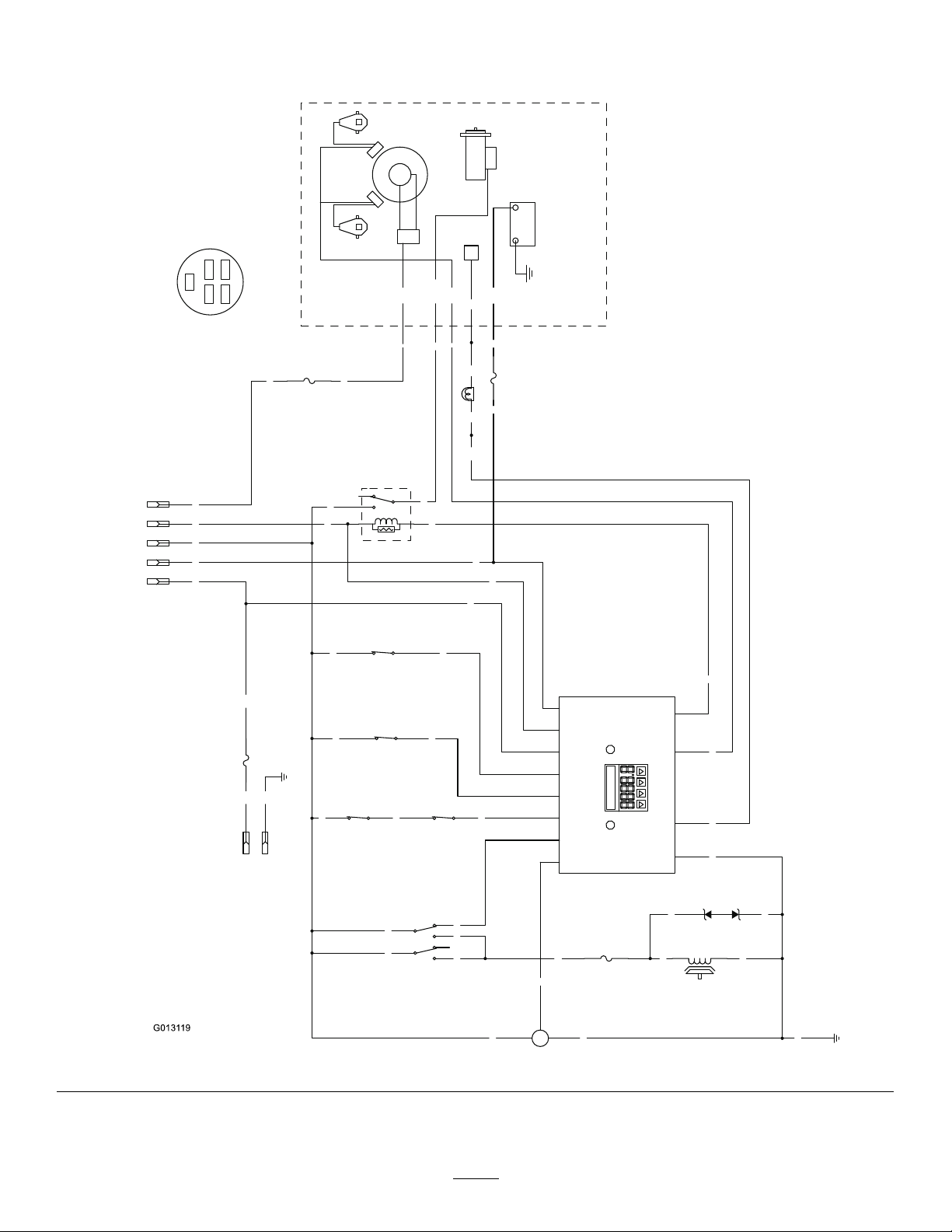
Schematics
BN
BN
BU
BK
Y
W
T
PK
BN
PK
OR
GN
S R
PK PK
PK
LTGR
GY
GY
PK
V
BN
V
OR
GN
OR
R
PK R BK
T
R
BK
GND
PK
BK
BN
BN
BK PK
BK
GND
15A
F4
GY
R
IBA
W
V
BU
V
V
BK
+
S
-
FUEL SENDER
10A
F3
(BRAKE)
SW6
PK
OR
R
F2
25A
PTO
CLUTCH
BU
1
2
5
4
7
8
(PTO SWITCH)
SW2
25A
LAMP
F1
(SEAT)
SW7
2
3
5
4
1
K2
(START RELAY)
TVS DIODE
U2
(NEUT_R)
SW5
B+
MAG
ECU
REG
START
AC
STARTER
+-
AC
IGNITION
MODULES
SPARK PLUGSPARK PLUG
KOHLER EFI
(NEUT_L)
SW4
12
B+
10
KEY_S
9
KEY_A
4
SEAT
11
BRAKE
2
NEUTRAL
3
PTO
5
FUEL
1
START_RELAY
7
MAGNETO
6
FUEL_SOLENOID
8
GROUND
HOUR METER
2
R A
I
A
4
7
1 3
6
5
A
3
SW1
1
B
B
C
B
8
2
4
5
(IGNITION)
6
5
1
KEY SW
OPTIONAL
ACCESSORIES
2
S
Ignition switch terminal locations
viewed from back
OFF = no connections
ON = BRIA
START = BRIS
BK = BLACK
BN = BROWN
BU = BLUE
GN = GREEN
GY = GREY
LT GR = LIGHT GREEN
OR = ORANGE
PK = PINK
R = RED
T = T
AN
V = VIOLET
W = WHITE
WireDiagram(Rev .A)
75
g013119
Page 76

TheToroTotalCoverageWarranty
ALimitedWarranty(seewarrantyperiodsbelow)Contractor
Landscape
Equipment
(LCE)
ConditionsandProductsCovered
TheToroCompanyanditsafliate,T oroWarrantyCompany ,pursuanttoanagreement
betweenthem,jointlypromisetotheoriginalpurchasertorepairtheT oroProducts
listedbelowifdefectiveinmaterialsorworkmanship.
Thefollowingtimeperiodsapplyfromthedateofpurchasebytheoriginalowner:
ProductsWarrantyPeriod
21in.Mowers2yearsResidentialUse
1yearCommercialUse
4
•Engines
Honda–2years
Kawasaki–3years
30in.Mowers2yearsResidentialUse
1yearCommercialUse
4
•Engines
Mid-SizeWalk-BehindMowers
4
•Engines
GrandStand
4
•Engines
•Frame
®
ZMaster
•Engines
2000SeriesMowers
4
•Frame
®
ZMaster
•Engines
•Frame
ZMaster
•Engines
4
®
4
3000SeriesMowers
5000SeriesMowers
®
Mowers
Kawasaki–3years
2years
Kawasaki–3years
5yearsor1,200hours
3years
Lifetime(originalowneronly)
4yearsor500hours
3years
Lifetime(originalowneronly)
5yearsor1,200hours
3years
Lifetime(originalowneronly)
5yearsor1,200hours
KohlerCommand–2years
KohlerEFI–3years
•Frame
®
ZMaster
•Engines
6000SeriesMowers
4
•Frame
®
ZMaster
•Engines
7000SeriesMowers
4
•Frame
Lifetime(originalowneronly)
5yearsor1,200hours
Kawasaki–3years
Lifetime(originalowneronly)
5yearsor1,200hours
2years
Lifetime(originalowneronly)
AllMowers
•Battery90daysPartsandLabor
1yearPartsonly
•BeltsandTires90days
•Attachments1year
1
Residentialusemeansuseoftheproductonthesamelotasyourhome.Useatmorethanone
locationisconsideredcommercialuseandthecommercialwarrantywouldapply.
2
Whicheveroccursrst.
3
LifetimeFrameWarranty-Ifthemainframe,consistingofthepartsweldedtogethertoformthe
tractorstructurethatothercomponentssuchastheenginearesecuredto,cracksorbreaksin
normaluse,itwillberepairedorreplaced,atT oro'soption,underwarrantyatnocostforpartsand
labor.Framefailureduetomisuseorabuseandfailureorrepairrequiredduetorustorcorrosion
arenotcovered.
4
SomeenginesusedonT oroProductsarewarrantedbytheenginemanufacturer.
1
1
2
3
2
3
2
3
2
3
2
3
2
3
InstructionsforObtainingWarrantyService
IfyouthinkthatyourT oroProductcontainsadefectinmaterialsorworkmanship,
followthisprocedure:
1.ContactanyAuthorizedT oroServiceDealertoarrangeserviceattheir
dealership.T olocateadealerconvenienttoyou,refertotheY ellowPagesof
yourtelephonedirectory(lookunder“LawnMowers”)oraccessourwebsite
atwww.Toro.com.Y oumayalsocallthenumberslistedinitem#3tousethe
24-hourT oroDealerlocatorsystem.
2.Bringtheproductandyourproofofpurchase(salesreceipt)totheService
Dealer.Thedealerwilldiagnosetheproblemanddetermineifitiscovered
underwarranty.
3.IfforanyreasonyouaredissatisedwiththeServiceDealer’sanalysisorwith
theassistanceprovided,contactusat:
RLCCustomerCareDepartment
ToroWarrantyCompany
811 1LyndaleAvenueSouth
Bloomington,MN55420-1 196
888-865-5676(U.S.Customers)
888-865-5691(Canadacustomers)
OwnerResponsibilities
YoumustmaintainyourT oroProductbyfollowingthemaintenanceprocedures
describedintheOperator'sManual.Suchroutinemaintenance,whetherperformedby
adealerorbyyou,isatyourexpense.
ItemsandConditionsNotCovered
Thereisnootherexpresswarrantyexceptforspecialemissionsystemcoverage
andenginewarrantycoverageonsomeproducts.Thisexpresswarrantydoesnot
coverthefollowing:
•Costofregularmaintenanceserviceorparts,suchaslters,fuel,lubricants,oil
changes,sparkplugs,airltersbladesharpeningorwornblades,cable/linkage
adjustments,orbrakeandclutchadjustments
•Componentsfailingduetonormalwear
•Anyproductorpartwhichhasbeenalteredormisusedorneglectedandrequires
replacementorrepairduetoaccidentsorlackofpropermaintenance
•Pickupanddeliverycharges
•RepairsorattemptedrepairsbyanyoneotherthananAuthorizedToroService
Dealer
•Repairsnecessaryduetofailuretofollowrecommendedfuelprocedure(consult
Operator'sManualformoredetails)
–Removingcontaminantsfromthefuelsystemisnotcovered
–Useofoldfuel(morethanonemonthold)orfuelwhichcontainsmorethan
10%ethanolormorethat15%MTBE
–Failuretodrainthefuelsystempriortoanyperiodofnon-useoverone
month
GeneralConditions
AllrepairscoveredbythesewarrantiesmustbeperformedbyanAuthorizedT oro
ServiceDealerusingToroapprovedreplacementparts.
NeitherTheToroCompanynorToroWarrantyCompanyisliableforindirect,
incidentalorconsequentialdamagesinconnectionwiththeuseoftheToro
Productscoveredbythiswarranty ,includinganycostorexpenseofproviding
substituteequipmentorserviceduringreasonableperiodsofmalfunctionor
non-usependingcompletionofrepairsunderthiswarranty .
Allimpliedwarrantiesofmerchantability(thattheproductistforordinaryuse)
andtnessforuse(thattheproductistforaparticularpurpose)arelimitedto
thedurationoftheexpresswarranty.
Somestatesdonotallowexclusionsofincidentalorconsequentialdamages,
orlimitationsonhowlonganimpliedwarrantylasts,sotheaboveexclusions
andlimitationsmaynotapplytoyou.
Thiswarrantygivesyouspeciclegalrights,andyoumayalsohaveotherrights
whichvaryfromstatetostate.
CountriesOtherthantheUnitedStatesorCanada
CustomerswhohavepurchasedToroproductsoutsidetheUnitedStatesorCanadashouldcontacttheirToroDistributor(Dealer)toobtainguaranteepoliciesforyourcountry ,
province,orstate.IfforanyreasonyouaredissatisedwithyourDistributor'sserviceorhavedifcultyobtainingguaranteeinformation,contacttheToroimporter.Ifallother
remediesfail,youmaycontactusatT oroWarrantyCompany .
AustralianConsumerLaw:AustraliancustomerswillnddetailsrelatingtotheAustralianConsumerLaweitherinsidetheboxoratyourlocalT oroDealer.
374-0252RevF
 Loading...