

Toro 72211, 72212 Addendum
417XT and 419XT
Wheel Horse Garden Tractor
Model No. 7221 1—240000001 and Up
Model No. 72212—240000001 and Up
Important The following instructions are updates for
the Setup instructions in the tractor Operator’s Manual.
Loose Parts
Note: Use the chart below to verify all parts have been shipped.
Description Qty. Use
Form No. 3351–401
Addendum
Steering Wheel
Lock Washer, 1/2 inch
Nut, 1/2 inch
Logo Cover
Seat
Spacer , small inside diameter
Spacer , large inside diameter
Shoulder Bolt
Knob
Flat Washer, 11/32 inch
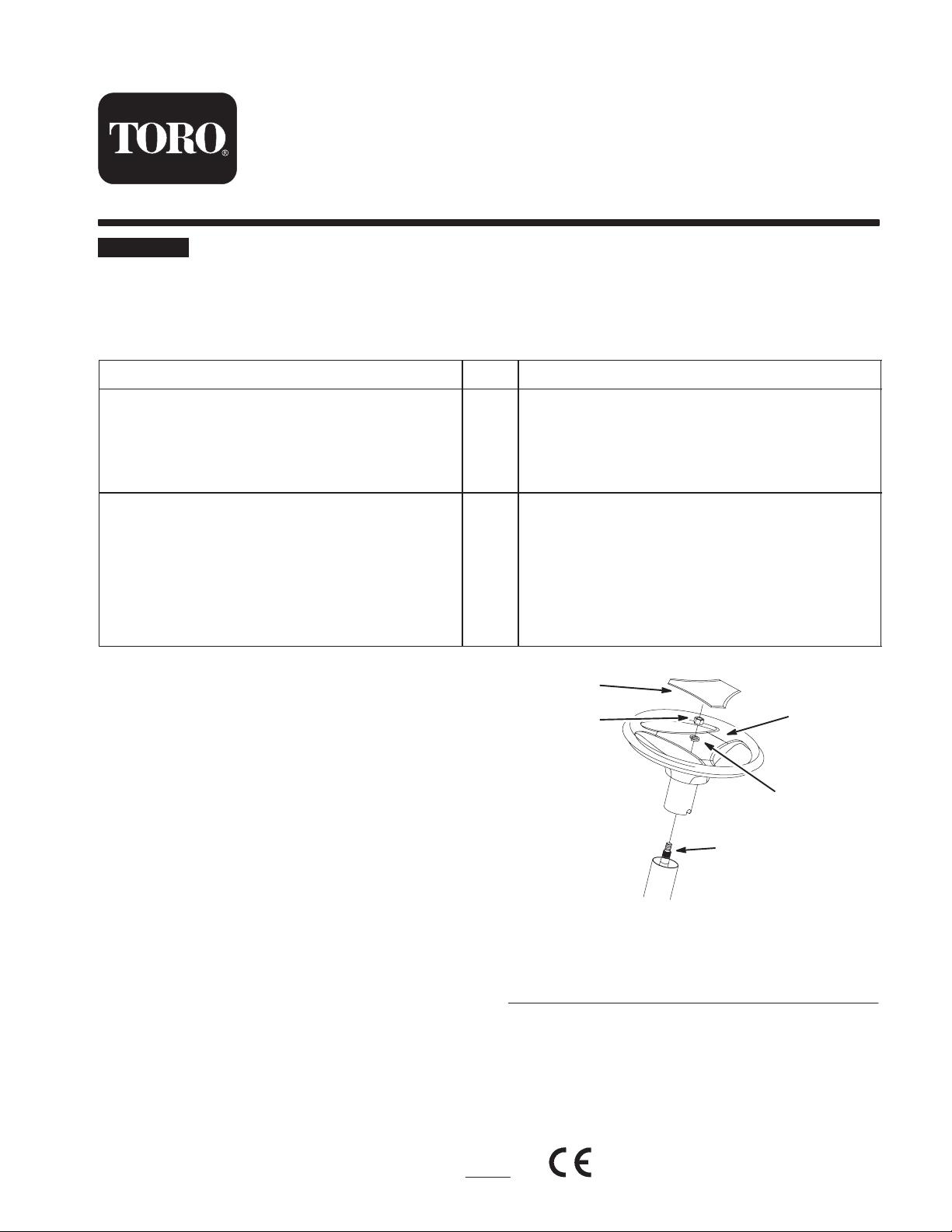
Installing the Steering Wheel
1. Position the front wheels straight ahead.
2. Remove the logo cover by releasing the 3 latches from
the back side with a screwdriver.
3. Line up the center spoke toward the seat and position
the steering wheel onto the shaft spline (Fig. 1).
4. Secure the steering wheel with a lockwasher (1/2 inch)
and nut (1/2 inch) (Fig. 1).
1
1
1
1
1
2
2
2
2
2
Install the steering wheel
Install the seat
5
4
1
3
2
5. Torque the steering wheel nut to 50 ft-lb (37 N.m).
6. Snap the logo cover into place (Fig. 1).
2003 by The Toro Company
8111 Lyndale Avenue South
Bloomington, MN 55420-1196
Figure 1
1. Center spoke
2. Shaft spline
3. Lock washer, 1/2 inch
4. Nut, 1/2 inch
5. Logo cover
Installing the Seat
1. Install the large inside diameter spacer and the 2
shoulder bolts into the rear holes of the seat (Fig. 2).
Contact us at www.Toro.com
1
Original Instructions (GB)
All Rights Reserved
Printed in the USA
2307
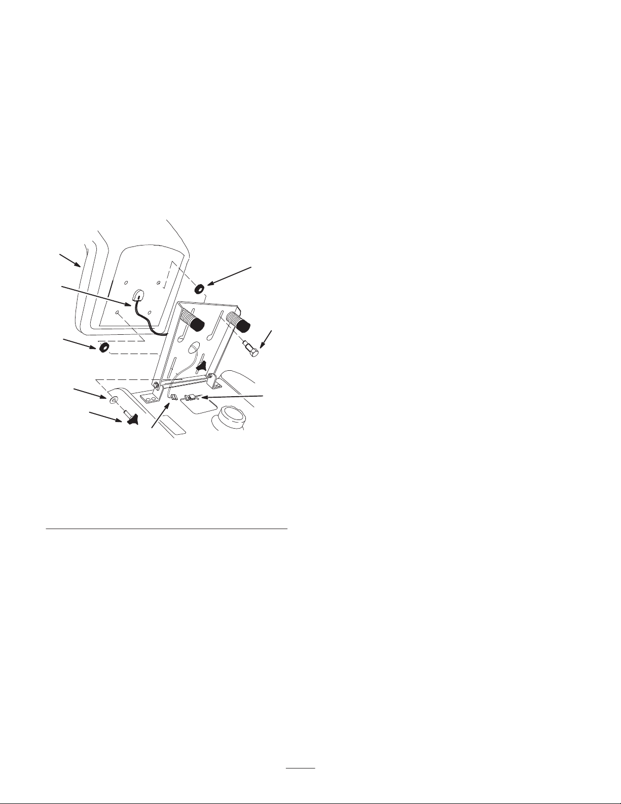
2. Position the seat onto the seat base by inserting the
2 shoulder bolts through the key hole openings at the
end of both slots (Fig. 2).
3. Locate the small inside diameter spacer between the
seat and the seat base, thread the 2 knobs and 2 flat
washers (11/32 inch) into the front holes in the seat
(Fig. 2). Adjust the seat and tighten the knobs.
4. Route the seat switch wire and connector through the
center opening in the seat base. Push the seat switch
connector fully into the wire harness connector (Fig. 2).
5. Secure the seat switch wire cable to the fender opening
(Fig. 2).
1
3
6
4
2
9
5
1. Seat
2. Spacer-small ID
3. Spacer-large ID
4. Shoulder bolt
5. Knob
7
Figure 2
8
m–5081
6. Wire and connector
7. Wire harness connector
8. Wire clip
9. Flat washer, 11/32 inch
2
 Loading...