

Toro 72201 Parts Catalogue

420 Garden Tractor
Model No. 72201 - 250000001 and up.
Form Number 3353-244
Parts Catalog
Ordering Replacement Parts
To order replacement parts, please supply the part
number, the quantity, and the description of each part
desired.
Understanding Reference Numbers
Each Identified part in an illustration has a reference
number. The reference number for a part also
appears in the parts list, along with other information
about the part.
This catalog uses two special reference number
formats, one to indicate parts in a service assembly
and another to indicate the quantity of a given part in
an illustration.
Service Assembly Reference Numbers
Parts in service assemblies have reference numbers
in the form a:b. The a represents the reference
number of the entire service assembly and the b
represents a sequential number unique to each part
within the service assembly.
© The Toro Company - 2005
Register your product at www.Toro.com
All Rights Reserved
For example, a wheel assembly might be identified
by reference number 6, the tire by 6:1, the valve by
6:2, and the wheel by 6:3. When you order the
assembly identified by reference number 6, you
receive all parts identified by reference numbers 6:1,
6:2, and 6:3. However, you may also order any part
individually. Reference numbers of this type appear
in illustrations and in part lists.
Reference Numbers Indicating Quantity
In an illustration, if a reference number indicates
more than one part, the reference number has the
form nX y. The n represents the quantity of the part,
the X is the multiplication symbol, and the y
represents the reference number.
For example, in an illustration, the reference number
2X 37 means that two of the parts identified by
reference number 37 are indicated.

Contents
Description Page
. . . . . . 3Hood and Grill Assembly
. . . . . . 4Hydro Drive Assembly
. . . . . . 5Front Axle and Hitch Assembly
. . . . . . 6PTO Stop Assembly
. . . . . . 7Engine, Muf f l er and PTO Asse m bly
. . . . . . 8Battery Assembly
. . . . . . 9Fuel Tank Assembly
. . . . . . 10Lower Steering Wheel and Tilt Assembly
. . . . . . 11Steering Wheel and Tilt Assembly
. . . . . . 12Hoodstand and Firewall Assembly
. . . . . . 13Manual Lift Lever Assembly
. . . . . . 14Lift Assembly
. . . . . . 15Brake Assembly
. . . . . . 16Hydro Control Assembly
. . . . . . 17Frame Assembly
. . . . . . 18Hydro Transaxle Assembly
Housing and Fan Assembly Transaxle
Assembly No. 104-4310
Differential Gear Assembly Transaxle
Assembly No. 104-4310
Brake Assembly Transaxle Assembly No. 1044310
Cylinder Block Assembly Transaxle Assembly
No. 104-4310
. . . . . . 19
. . . . . . 20
. . . . . . 21
. . . . . . 22
. . . . . . 23Fender and Foot rest Assemb l y
Description Page
. . . . . . 24Seat Assembly
. . . . . . 25Dash Assembly
. . . . . . 26Rear Wheel Assembly
. . . . . . 27Cruise Control Assembly
Cylinder and Crankcase Assembly Kawasaki
FH541V-DS04
Piston and Crankshaft Assembly Kawasaki
FH541V-DS04
Valve and Camshaft Assembly Kawasaki
FH541V-DS04
Cooling Equipment Assembly Kawasaki
FH541V-DS04
Lubrication Equipment Assembly Kawasaki
FH541V-DS04
Electric Equipment Assembly Kawasaki
FH541V-DS04
Control Equipment Assembly Kawasaki
FH541V-DS04
Air Filter and Muffler Assembly Kawasaki
FH541V-DS04
Fuel Tank and Valve Assembly Kawasaki
FH541V-DS04
. . . . . . 28
. . . . . . 29
. . . . . . 30
. . . . . . 31
. . . . . . 32
. . . . . . 34
. . . . . . 35Carburetor Assembly Kawasaki FH541V-DS04
. . . . . . 36
. . . . . . 38
. . . . . . 39
. . . . . . 40Starter Assembly Kawasaki FH541V-DS04
. . . . . . 42Label Assembly Kawasaki FH541V-DS04
Part Description Abbreviations
Part descriptions in this catalog may include the following abbreviations.
AR. . . . . . . . . . . . . . .as required
ASM. . . . . . . . . . . . . assembly
BBC. . . . . . . . . . . . . blade brake clutch
CARR. . . . . . . . . . . . carriage
DEG. . . . . . . . . . . . . degrees
EXT. . . . . . . . . . . . . .external
FH. . . . . . . . . . . . . . . flat head
GA. . . . . . . . . . . . . . gauge
HF. . . . . . . . . . . . . . . hex flange
HH. . . . . . . . . . . . . . hex head
HHF. . . . . . . . . . . . . hex head flange
HHFTF. . . . . . . . . . . hex head flange thread forming
HJ. . . . . . . . . . . . . . . hex jam
HLH. . . . . . . . . . . . . hex lag head
HOC. . . . . . . . . . . . . height-of-cut
HSBH. . . . . . . . . . . . hex socket button head
HSFH. . . . . . . . . . . . hex socket flat head
HSH. . . . . . . . . . . . . hex socket head
HWH. . . . . . . . . . . . . hex washer head
HWHTF. . . . . . . . . . . hex washer head thread
HYD. . . . . . . . . . . . . hydraulic
INC. . . . . . . . . . . . . . incorporated
LH. . . . . . . . . . . . . . . left hand
NI. . . . . . . . . . . . . . . nylon insert
NPTF. . . . . . . . . . . . national pipe thread fine
PPH. . . . . . . . . . . . . phillips pan head
PPHTF. . . . . . . . . . . phillips pan head thread
PRH. . . . . . . . . . . . . phillips round head
PTH. . . . . . . . . . . . . phillips truss head
PTO. . . . . . . . . . . . . power take off
RH. . . . . . . . . . . . . . right hand
ROPS. . . . . . . . . . . . roll over protection system
SFH. . . . . . . . . . . . . slotted fillister head
SHH. . . . . . . . . . . . . slotted hex head
SHWH. . . . . . . . . . . . slotted hex washer head
SPH. . . . . . . . . . . . . slotted pan head
SQH. . . . . . . . . . . . . square head
Footnotes
n
p
Not illustrated
Obtain from your local Kawasaki dealer
o
forming
forming
Not serviced separately
2
3353-244
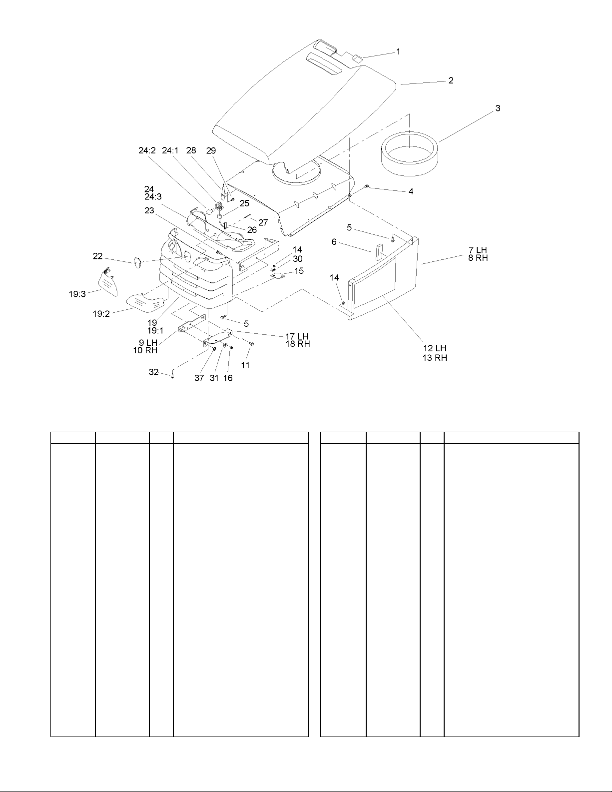
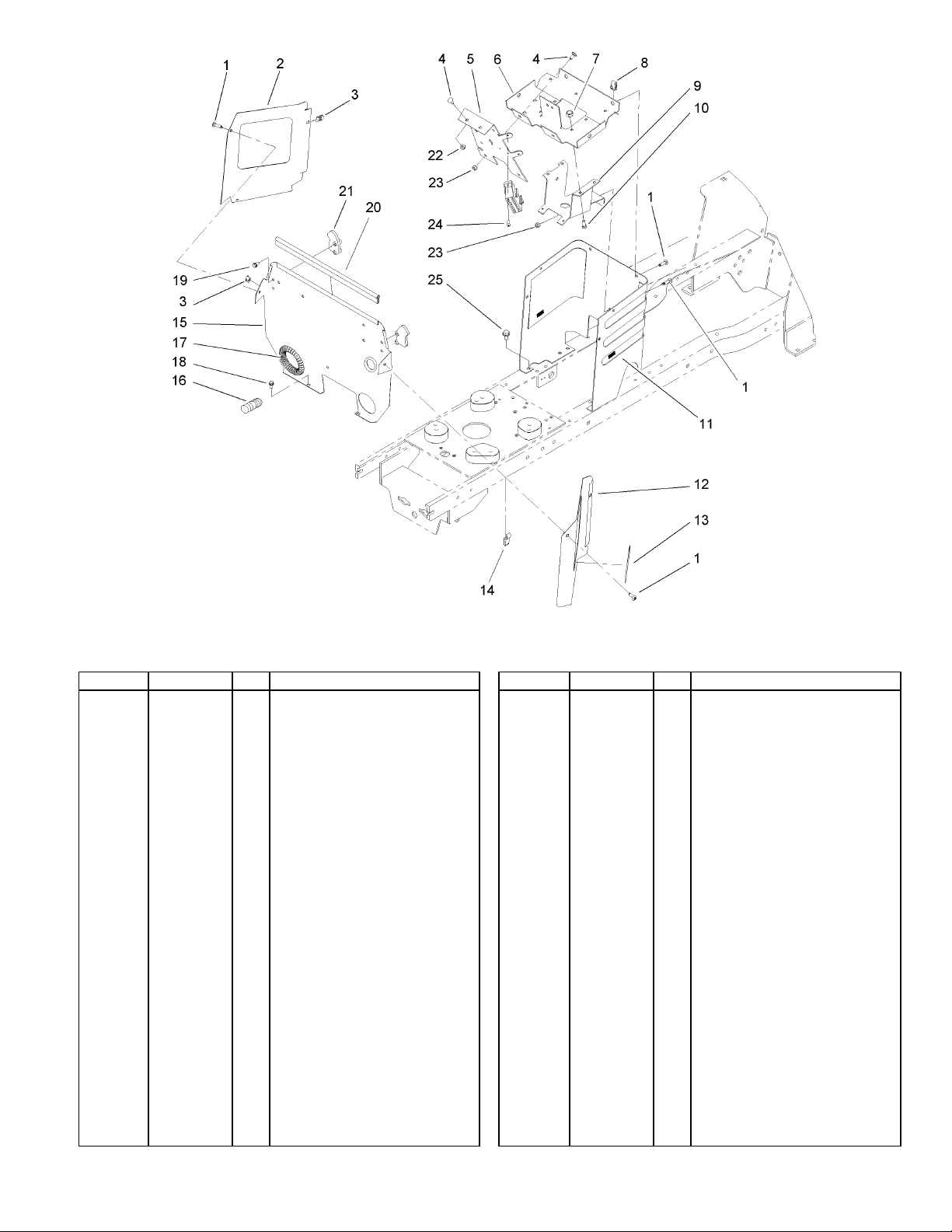
Hood and Grill Assembly
Ref Part No. Qty. Description
Foam-Hood1
94-1980
93-0490
92-7076
92-7006
32105-15
92-7148
93-0491
93-0492
106-5673-03
106-5672-03
32144-14
107-8902
107-8913
32128-10
106-5676-03
3296-29
106-5680-03
106-5682-03
o
106-5595
106-5693
106-5692
95-4248
3230-16
2
Hood ASM2
1
Seal-Air Inlet, Twin3
1
Nut4
4
Screw5
8
Foam-Sidepanel6
2
Hood-Side, LH7
1
Hood-Side, RH8
1
Bracket-Hinge, LH9
1
Bracket-Hinge, RH10
1
Screw-HWH11
2
Decal-Hood, LH12
1
Decal-Hood, RH13
1
Nut-Lock, HHF14
8
Hinge-Hood15
2
Nut-Lock, NI16
2
Bracket-Hood, Hinge, LH17
1
Bracket-Hood, Hinge, RH18
1
Grille ASM19
1
Grille19:1
1
Lens-LH19:2
1
Lens-RH19:3
1
Decal22
1
Screw-CARR23
2
Ref Part No. Qty. Description
1
106-9870
116262
7228
106-9869
106-9890
614249
94-6961
92-6914-03
46-8093
2412-89
98-2390
321-5
106-8745
Reflector And Lamp ASM24
Socket-Headlight24:1
2
Bulb24:2
2
Reflector24:3
1
Harness-Wire, Headlights25
1
Strap-Tie26
2
Screw27
2
Baffle-Hood, Upper28
1
Screw-Plastite29
2
Clamp30
1
Clamp-R31
1
Screw-HH32
4
O-Ring37
1
3
3353-244
3
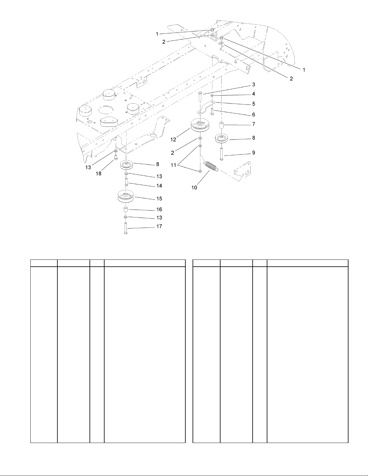
Ref Part No. Qty. Description
Nut-Lock, NI1
3296-39
3256-24
323-10
106-5597
106-5566-03
323-7
106-5565
93-0320
323-13
106-5598
3296-59
92-7101
3253-5
323-8
92-7104
106-5574
323-12
323-4
2
Washer-Flat2
3
Screw-HH3
1
Spacer-Idler, Traction4
1
Bracket-Idler5
1
Screw-HH6
1
Spacer-Idler7
1
Pulley-Idler8
2
Screw-HH9
1
Spring-Extension10
1
Nut-Lock, NI11
2
Pulley-Idler, Flat12
1
Washer-Lock13
3
Screw-HH14
1
Pulley-Idler15
1
Spacer-Mounting, Steering16
1
Screw-HH17
1
Screw-HH18
1
Hydro Drive Assembly
4
4
3353-244
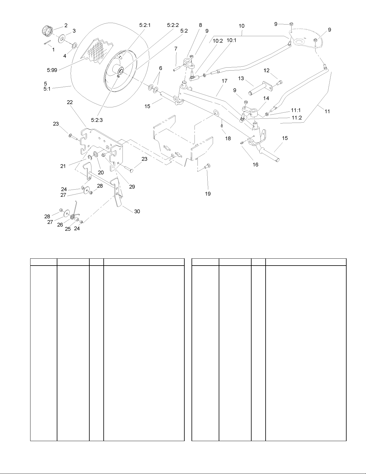
Front Axle and Hitch Assembly
Ref Part No. Qty. Description
Pin-Cotter1
3272-17
61-9780
28-2480
1278
o
99-2336
93-9801
5108
110513
109500
105293
5210
933270
78-1950-03
9150026
92-6883
9150854
78-2920
92-6884
9150854
78-2920
9267154
92-7057-03
78-1940-03
2
Cap-Hub2
2
Washer3
2
Washer4
2
Front Wheel And Tire ASM5
2
Tire5:1
1
Wheel ASM5:2
1
Valve5:2:1
1
Bearing-Wheel5:2:2
2
Zerk-Grease5:2:3
1
Tube-Inner5:99
1
Washer-Shim6
4
Pin7
2
Arm-Spindle, LH8
1
Nut9
4
Linkage-Steering, RH10
1
Nut-Jam10:1
1
Ball-Joint10:2
1
Linkage-Steering, LH11
1
Nut-Jam11:1
1
Ball-Joint11:2
1
Screw12
1
Pin-Axle13
1
Arm-Spindle, RH14
1
Ref Part No. Qty. Description
2
78-2601-03
302-5
78-7960-03
302-11
3231-25
9202324
5618
106-4044-03
3230-5
92-6998
107-3677
106-4048
3256-68
3296-29
3296-39
106-5637-03
Spindle15
Fitting-Grease16
2
Axle-Front17
1
Fitting-Lube, 45 DEG18
1
Screw-CARR19
4
Washer20
1
E-Ring21
1
Hitch-Front22
1
Screw-CARR23
2
Spacer-Yoke, Right24
2
Spacer-Tube25
1
Spring-Torsion26
1
Washer-Flat27
2
Nut-Lock, NI28
2
Nut-Lock, NI29
4
Latch ASM30
1
5

3353-244
5
Ref Part No. Qty. Description
Washer-Lock16
3253-5
323-4
107-3662-03
32144-4
2412-89
2
Screw-HH17
2
PTO Stop ASM18
1
Screw-HWH20
1
Clamp21
1
PTO Stop Assembly
6
6
3353-244
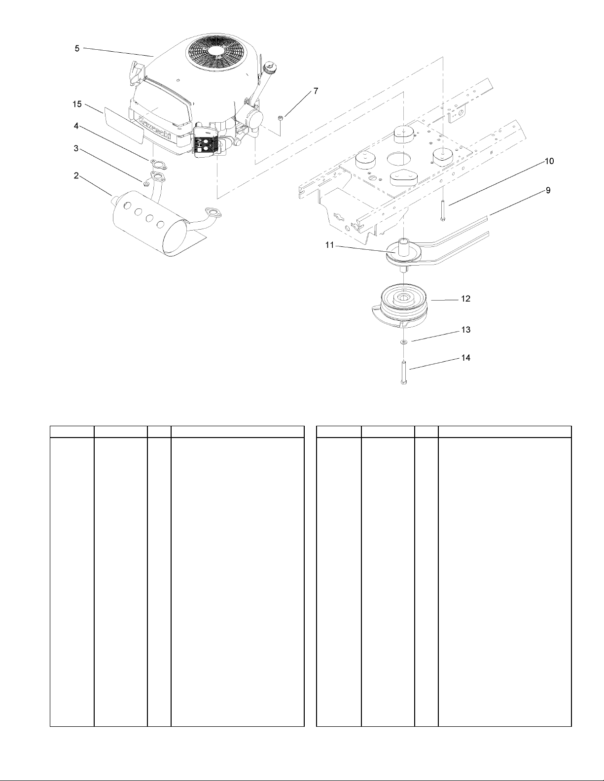
Engine, Muffler and PTO Assembly
Ref Part No. Qty. Description
Muffler2
106-5666
92-6780
93-0350
o
3296-29
106-5813
322-13
106-5665
106-4099
3256-25
3212-19
107-9246
1
Nut-HF3
4
Gasket-Exhaust4
2
Engine-Kawasaki, FH541V-Ds045
1
Nut-Lock, NI7
4
V-Belt, Traction9
1
Screw-HH10
4
Pulley-Engine11
1
Clutch12
1
Washer-Flat13
1
Screw-HH14
1
Decal15
1
7
3353-244
7
Ref Part No. Qty. Description
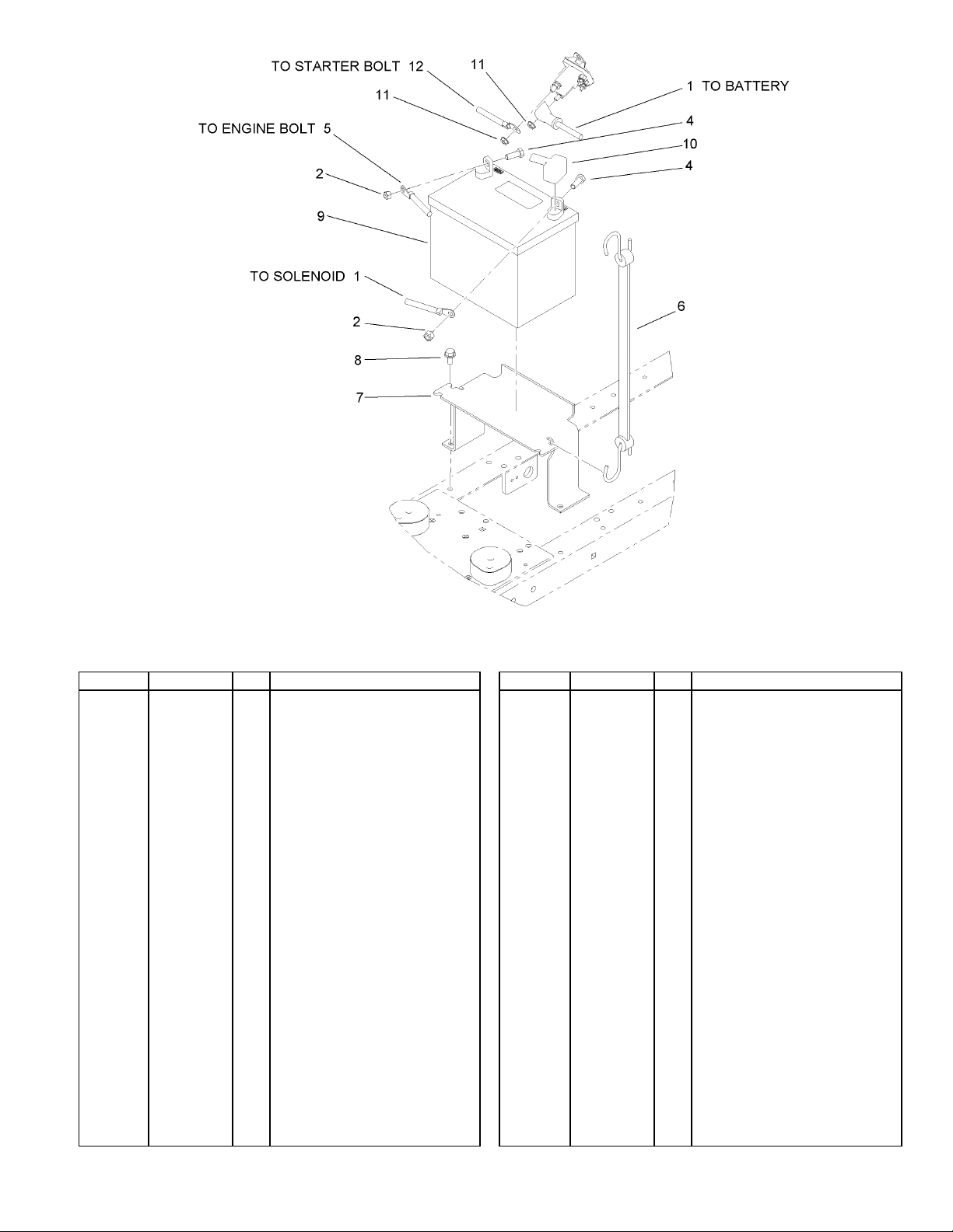
Cable-Battery, Red1
106-8268
3296-29
322-4
105-0836
104-2467
104-0812-03
32144-14
104-2492
28-8080
32149-2
106-8269
1
Nut-Lock, NI2
2
Screw-HH4
2
Cable-Battery, Black5
1
Hold-Down, Battery6
1
Bracket-Battery7
1
Screw-HWH8
2
Battery9
1
Boot-Terminal10
1
Nut-Keps11
2
Cable-Battery, Red12
1
Battery Assembly
8
8
3353-244
Ref Part No. Qty. Description
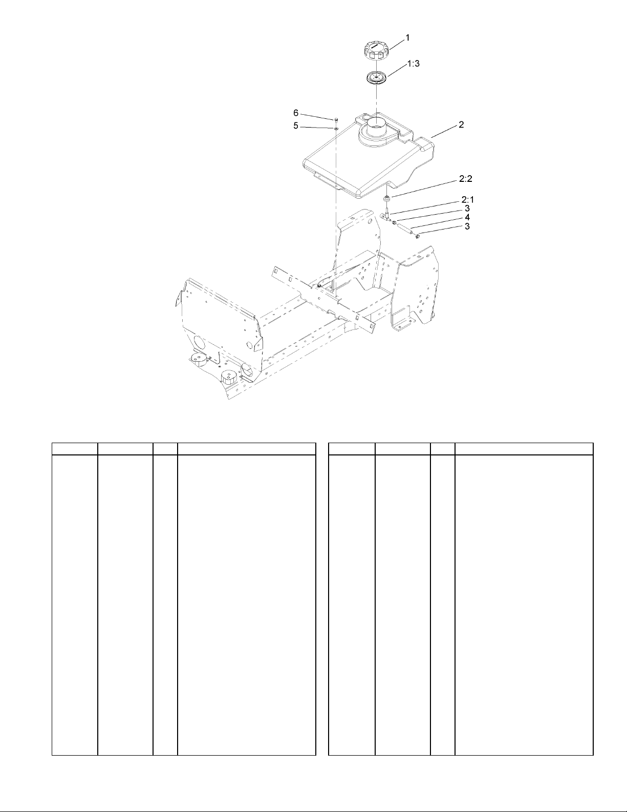
Gas Cap ASM1
88-3980
88-4010
94-6928
104048
104047
2412-98
106-9876
3256-22
32144-4
1
Gasket-Cap, Gas1:3
1
Tank-Gas2
1
Valve-Fuel2:1
1
Bushing2:2
1
Clamp3
2
Hose-Line, Fuel4
1
Washer-Flat5
2
Screw-HWH6
2
Fuel Tank Assembly
9
3353-244
9
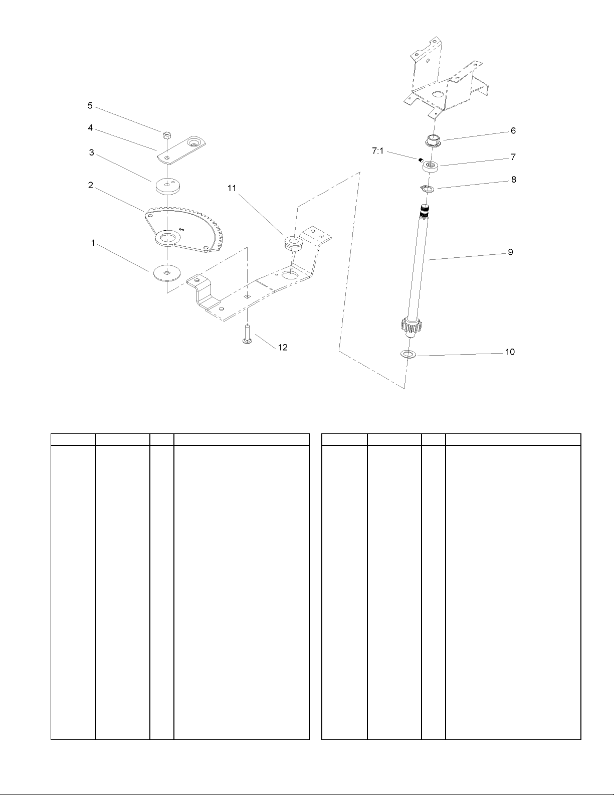
Lower Steering Wheel and Tilt Assembly
Ref Part No. Qty. Description
Washer-Bearing1
111419
106-8262
111418
78-9150-03
108881
109189
111383
3245-32
111646
92-6702
1278
110391
3231-4
1
Sector-Gear2
1
Bushing3
1
Plate4
1
Nut5
1
Bearing-Flanged6
1
Collar7
1
Screw-HSH7:1
1
Ring-Retaining8
1
Shaft-Steering, Lower9
1
Washer10
1
Bearing-Wheel11
1
Screw-CARR12
1
10
10
3353-244
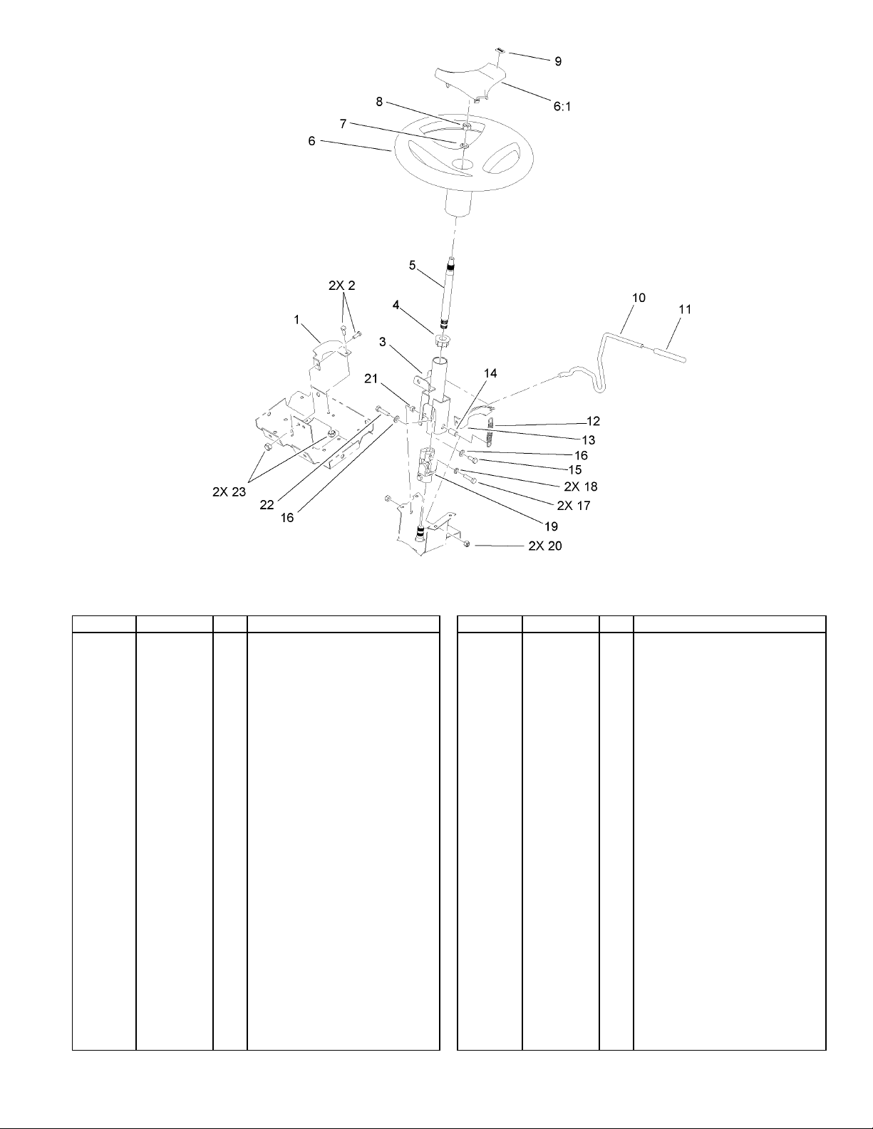
Steering Wheel and Tilt Assembly
Ref Part No. Qty. Description
Bracket-Support, Column1
92-6777-03
321-4
93-1148-03
93-1146
94-2874
98-1472
98-1468
3253-7
3217-9
98-1459
92-6971
92-6798
93-1357
92-6776
92-6999
322-3
3256-23
33114-030
3253-4
92-6717
3296-29
92-6998
322-17
3296-8
1
Screw-HH2
4
Column ASM3
1
Bushing-Upper, Steering4
1
Shaft-Short, Steering5
1
Wheel-Steering6
1
Cover-Wheel, Steering6:1
1
Washer-Lock7
1
Nut-Hex8
1
Decal9
1
Lever-Tilt10
1
Cap-Rod, Tilt11
1
Spring-Extension12
1
Bracket-Detent13
1
Spacer-Yoke14
1
Screw-HH15
1
Washer-Flat16
2
Screw-HH17
2
Washer-Lock18
2
U-Joint, Steering19
1
Nut-Lock, NI20
2
Spacer-Yoke, Right21
1
Screw-HH22
1
Nut-Lock23
4
11
3353-244
11
Hoodstand and Firewall Assembly
Ref Part No. Qty. Description
Screw-HH1
92-7020
92-6937-03
92-7006
3229-11
106-8246-03
92-6859-03
3296-8
107069
92-6778-03
321-4
106-5570-03
92-6936-03
107-9242
212-93
104-0818-03
106-4147
24-7924
32144-4
46-8093
93-1131
92-6960
32149-2
3296-42
32144-8
12
9
RH Side Cover ASM2
1
Nut3
4
Screw-CARR4
4
Panel-Support, Dash5
1
Support-Dash6
1
Nut-Lock7
4
Clip8
4
Bracket-Colu m n , Lo we r9
1
Screw-HH10
4
Hoodstand ASM11
1
LH Cover ASM12
1
Decal13
2
Clamp-Casing14
1
Firewall15
1
Harness-Wire16
1
Cover-Shaft, Drive17
2
Screw-HWH18
2
Screw-Plastite19
2
Trim-Seal, Firewall20
1
Latch-Hood21
2
Nut-Keps22
2
Nut-Lock, NI23
3
Screw-HH24
2
Ref Part No. Qty. Description
2
32144-14
Screw-HWH25
12
3353-244
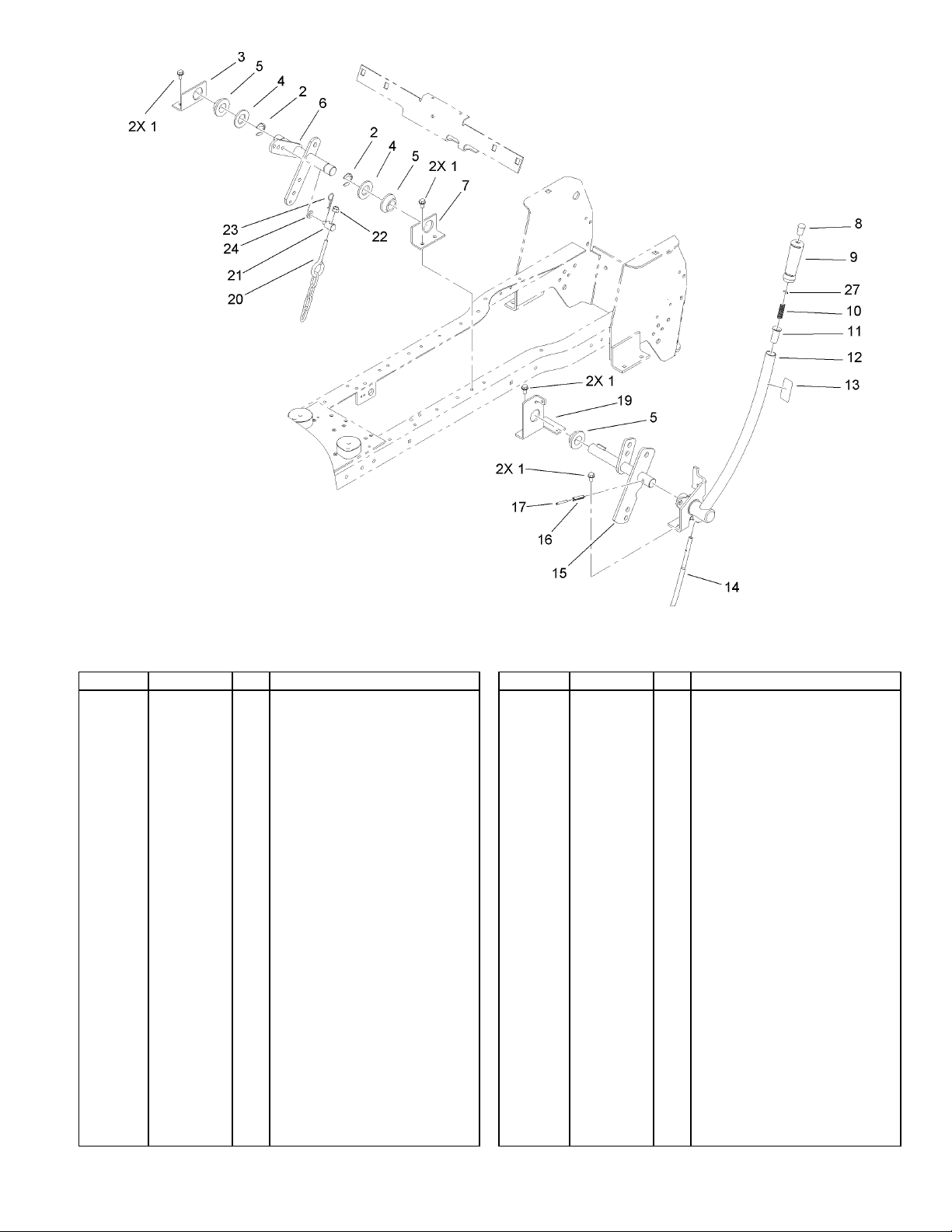
Manual Lift Lever Assembly
Ref Part No. Qty. Description
Screw-HWH1
32144-14
32151-91
106-5650-03
3256-62
106269
106-5660-03
106-5652-03
92-6711
92-6710
3624
8130
106-5663-03
112168
92-6977-03
106-5656-03
32121-25
32121-103
106-4073-03
106522
79-2790
3296-39
9335054
3256-24
933148
8
Ring-Retaining2
2
Bracket-Pivot Linkage, RH3
1
Washer-Flat4
2
Bearing-Flange5
3
Lift Lever ASM6
1
Bracket-Pivot Linkage, LH7
1
Tip-Rod8
1
Grip-Handle9
1
Spring-Compression10
1
Retainer-Spring11
1
Lift Lever ASM12
1
Decal-Lift13
1
Rod-Lever, Lift14
1
Lift Arm ASM15
1
Pin-Roll16
1
Pin-Spring17
1
Bracket-Pivot, Lift19
1
Chain-Lift20
1
Trunnion21
1
Nut-Lock, NI22
1
Pin-Hair23
1
Washer-Flat24
1
Pin-Spirol27
1
13
3353-244
13
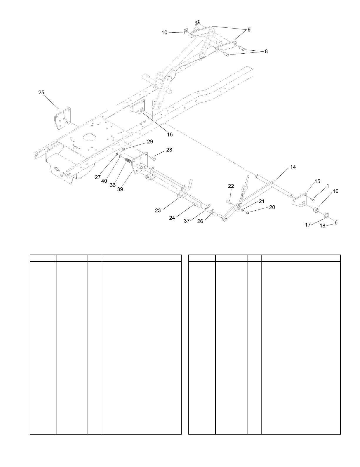
Ref Part No. Qty. Description
Screw-HWH1
32144-14
98-1639
106-5691-03
95-4064
106-4065-03
106-4066
98-1636
3256-28
32151-48
3296-29
3256-23
322-6
106-4091
107-3663
106-4060
3256-26
105797
323-46
3296-39
101853
9335054
107-3665
3256-24
2
Pin-Clevis8
2
Strap-Link, Lif t9
2
Clip-Pin10
2
Lift Bar ASM14
1
Plate-Lift, Rear15
2
Bushing-Flange16
2
Washer-Flat17
2
E-Ring18
2
Nut-Lock, NI20
1
Washer-Flat21
1
Screw-HH22
1
Midhitch Latch ASM23
1
Rod-Catch24
1
Plate-Hitch25
1
Washer-Flat26
1
Ring-Retaining27
1
Screw-HH28
6
Nut-Lock, NI29
6
Spring-Compression36
1
Pin-Hair37
1
Midhitch ASM39
1
Washer-Flat40
1
Lift Assembly
14
 Loading...