

Page 1

400XT Series Tractor
Service
Manual
Page 2

ABOUT THIS MANUAL
This service manual was written expressly for Toro service technicians. The Toro Company
has made every effort to make the information in this manual complete and correct.
Basic shop safety knowledge and mechanical/electrical skills are assumed. The Table of
Contents lists the systems and the related topics covered in this manual.
For additional information on the electrical system, please refer to the Toro Electrical
Demystification Guide (492-4404). For service information on drive systems, please refer to
the Hydro-Gear (330-3000) service manual. For information information specific to the
engines used on this unit, refer to the appropriate engine manufacturer’s service and repair
instructions.
Tractor model years 2003 - 2004 are covered in this manual. The manual may also be
specified for use on later model products.
The hydrostatic transaxle is a sophisticated piece of machinery. Maintain strict cleanliness
control during all stages of service and repair. Cover or cap all hose ends and fittings
whenever they are exposed. Even a small amount of dirt or other contamination can
severely damage the system.
We are hopeful that you will find this manual a valuable addition to your service shop. If you
have questions or comments regarding this manual, please contact us at the following
address:
The Toro Company
Consumer Service Department
8111 Lyndale Avenue South
Bloomington, MN 55420-1196
The Toro Company reserves the right to change product specifications or this manual
without notice.
Copyright© All Rights Reserved
©2003 The Toro Company
Page 3

SPECIFICATIONS
General Information . . . . . . . . . . . . . . . . . . . . . . . . . . . . . . . . . . . . . . . . . . . . . . . . .1 - 1
Think Safety First . . . . . . . . . . . . . . . . . . . . . . . . . . . . . . . . . . . . . . . . . . . . . . . . . . .1 - 1
General Specifications . . . . . . . . . . . . . . . . . . . . . . . . . . . . . . . . . . . . . . . . . . . . . . .1 - 2
Hydrostatic Transaxle . . . . . . . . . . . . . . . . . . . . . . . . . . . . . . . . . . . . . . . . . . . . . . . .1 - 3
Identification: Hydro-Gear Model 330-3000 Transaxle . . . . . . . . . . . . . . . . . . . . .1 - 3
General Specifications . . . . . . . . . . . . . . . . . . . . . . . . . . . . . . . . . . . . . . . . . . . . . . .1 - 3
Torque Specifications . . . . . . . . . . . . . . . . . . . . . . . . . . . . . . . . . . . . . . . . . . . . . . . .1 - 4
Fastener Identification . . . . . . . . . . . . . . . . . . . . . . . . . . . . . . . . . . . . . . . . . . . . .1 - 4
Standard Torque for Dry, Zinc Plated, and Steel Fasteners (Inch Series) . . . . . . . .1 - 5
Standard Torque for Dry, Zinc, and Steel Fasteners (Metric Fasteners) . . . . . . . . .1 - 6
Other Torque Specifications . . . . . . . . . . . . . . . . . . . . . . . . . . . . . . . . . . . . . . . . . . .1 - 7
SAE Grade 8 Steel Set Screws . . . . . . . . . . . . . . . . . . . . . . . . . . . . . . . . . . . . . .1 - 7
Thread Cutting Screws (Zinc Plated Steel) . . . . . . . . . . . . . . . . . . . . . . . . . . . . .1 - 7
Conversion Factors . . . . . . . . . . . . . . . . . . . . . . . . . . . . . . . . . . . . . . . . . . . . . . .1 - 7
Wheel Bolts and Lug Nuts . . . . . . . . . . . . . . . . . . . . . . . . . . . . . . . . . . . . . . . . . .1 - 7
Thread Cutting Screws (Zinc Plated Steel) . . . . . . . . . . . . . . . . . . . . . . . . . . . . .1 - 7
Equivalents and Conversions . . . . . . . . . . . . . . . . . . . . . . . . . . . . . . . . . . . . . . . . . .1 - 8
Decimal and Millimeter Equivalents . . . . . . . . . . . . . . . . . . . . . . . . . . . . . . . . . . . . .1 - 8
U.S. to Metric Conversions . . . . . . . . . . . . . . . . . . . . . . . . . . . . . . . . . . . . . . . . . . . .1 - 9
TABLE OF CONTENTS
CHASSIS
Model and Serial Number Location . . . . . . . . . . . . . . . . . . . . . . . . . . . . . . . . . . . . .2 - 1
Greasing and Lubrication . . . . . . . . . . . . . . . . . . . . . . . . . . . . . . . . . . . . . . . . . . . . .2 - 1
Front Wheel Toe-in . . . . . . . . . . . . . . . . . . . . . . . . . . . . . . . . . . . . . . . . . . . . . . . . . .2 - 1
Front Wheel Toe-in Adjustment . . . . . . . . . . . . . . . . . . . . . . . . . . . . . . . . . . . . . . . .2 - 2
Front Wheel and Spindle Removal and Installation . . . . . . . . . . . . . . . . . . . . . . . . .2 - 3
Front Axle Removal and Installation . . . . . . . . . . . . . . . . . . . . . . . . . . . . . . . . . . . . .2 - 4
Steering Gear . . . . . . . . . . . . . . . . . . . . . . . . . . . . . . . . . . . . . . . . . . . . . . . . . . . . . .2 - 5
Steering Backlash Adjustment . . . . . . . . . . . . . . . . . . . . . . . . . . . . . . . . . . . . . . . . .2 - 5
Steering Gear Shaft Disassembly . . . . . . . . . . . . . . . . . . . . . . . . . . . . . . . . . . . . . . .2 - 7
Steering Gear Assembly . . . . . . . . . . . . . . . . . . . . . . . . . . . . . . . . . . . . . . . . . . . . . .2 - 9
Sector Gear Disassembly . . . . . . . . . . . . . . . . . . . . . . . . . . . . . . . . . . . . . . . . . . . .2 - 11
Sector Gear Assembly . . . . . . . . . . . . . . . . . . . . . . . . . . . . . . . . . . . . . . . . . . . . . .2 - 11
Tilt Steering . . . . . . . . . . . . . . . . . . . . . . . . . . . . . . . . . . . . . . . . . . . . . . . . . . . . . . .2 - 12
Tilt Steering Disassembly . . . . . . . . . . . . . . . . . . . . . . . . . . . . . . . . . . . . . . . . . . . .2 - 13
Tilt Steering Assembly . . . . . . . . . . . . . . . . . . . . . . . . . . . . . . . . . . . . . . . . . . . . . .2 - 13
Steering Specifications . . . . . . . . . . . . . . . . . . . . . . . . . . . . . . . . . . . . . . . . . . . . . .2 - 14
Hood Removal . . . . . . . . . . . . . . . . . . . . . . . . . . . . . . . . . . . . . . . . . . . . . . . . . . . .2 - 15
Seat and Fender Removal . . . . . . . . . . . . . . . . . . . . . . . . . . . . . . . . . . . . . . . . . . .2 - 15
Gas Tank Removal . . . . . . . . . . . . . . . . . . . . . . . . . . . . . . . . . . . . . . . . . . . . . . . . .2 - 16
Removal . . . . . . . . . . . . . . . . . . . . . . . . . . . . . . . . . . . . . . . . . . . . . . . . . . . . . . . .2 - 3
Description . . . . . . . . . . . . . . . . . . . . . . . . . . . . . . . . . . . . . . . . . . . . . . . . . . . . . .2 - 5
Description . . . . . . . . . . . . . . . . . . . . . . . . . . . . . . . . . . . . . . . . . . . . . . . . . . . . .2 - 12
Installation . . . . . . . . . . . . . . . . . . . . . . . . . . . . . . . . . . . . . . . . . . . . . . . . . . . . .2 - 17
400XT Series Tractor Service Manual iii
Page 4

TABLE OF CONTENTS
CHASSIS (cont’d)
Lift Bar Assembly . . . . . . . . . . . . . . . . . . . . . . . . . . . . . . . . . . . . . . . . . . . . . . . . . 2 - 17
Removal . . . . . . . . . . . . . . . . . . . . . . . . . . . . . . . . . . . . . . . . . . . . . . . . . . . . . . 2 - 17
Lift Lever Assembly . . . . . . . . . . . . . . . . . . . . . . . . . . . . . . . . . . . . . . . . . . . . . . . . 2 - 18
Removal . . . . . . . . . . . . . . . . . . . . . . . . . . . . . . . . . . . . . . . . . . . . . . . . . . . . . . 2 - 18
Assembly . . . . . . . . . . . . . . . . . . . . . . . . . . . . . . . . . . . . . . . . . . . . . . . . . . . . . 2 - 18
Lift Arm/Lift Lever Assembly . . . . . . . . . . . . . . . . . . . . . . . . . . . . . . . . . . . . . . . . . 2 - 19
Removal . . . . . . . . . . . . . . . . . . . . . . . . . . . . . . . . . . . . . . . . . . . . . . . . . . . . . . 2 - 19
Installation . . . . . . . . . . . . . . . . . . . . . . . . . . . . . . . . . . . . . . . . . . . . . . . . . . . . . 2 - 20
Electric Lift . . . . . . . . . . . . . . . . . . . . . . . . . . . . . . . . . . . . . . . . . . . . . . . . . . . . . . . 2 - 21
Removal . . . . . . . . . . . . . . . . . . . . . . . . . . . . . . . . . . . . . . . . . . . . . . . . . . . . . . 2 - 21
Installation . . . . . . . . . . . . . . . . . . . . . . . . . . . . . . . . . . . . . . . . . . . . . . . . . . . . . 2 - 21
HYDRO-GEAR TRANSAXLE
Hydro-Gear Hydrostatic Transaxle . . . . . . . . . . . . . . . . . . . . . . . . . . . . . . . . . . . . . 3 - 1
Internal Service . . . . . . . . . . . . . . . . . . . . . . . . . . . . . . . . . . . . . . . . . . . . . . . . . . 3 - 1
Fluid Change . . . . . . . . . . . . . . . . . . . . . . . . . . . . . . . . . . . . . . . . . . . . . . . . . . . . 3 - 1
Transaxle Removal . . . . . . . . . . . . . . . . . . . . . . . . . . . . . . . . . . . . . . . . . . . . . . . . . 3 - 1
Installation - Hydro-Gear Transaxle . . . . . . . . . . . . . . . . . . . . . . . . . . . . . . . . . . 3 - 4
Neutral Adjustment . . . . . . . . . . . . . . . . . . . . . . . . . . . . . . . . . . . . . . . . . . . . . . . . . 3 - 7
Transaxle Purging Procedures . . . . . . . . . . . . . . . . . . . . . . . . . . . . . . . . . . . . . . 3 - 8
Brake . . . . . . . . . . . . . . . . . . . . . . . . . . . . . . . . . . . . . . . . . . . . . . . . . . . . . . . . . . . . 3 - 9
Checking the Brake . . . . . . . . . . . . . . . . . . . . . . . . . . . . . . . . . . . . . . . . . . . . . . . 3 - 9
Brake Adjustment . . . . . . . . . . . . . . . . . . . . . . . . . . . . . . . . . . . . . . . . . . . . . . . . . . 3 - 9
Foot Control Adjustment . . . . . . . . . . . . . . . . . . . . . . . . . . . . . . . . . . . . . . . . . . . . 3 - 10
Traction Belt Replacement . . . . . . . . . . . . . . . . . . . . . . . . . . . . . . . . . . . . . . . . . . 3 - 11
ELECTRICAL SYSTEMS
Electrical Systems . . . . . . . . . . . . . . . . . . . . . . . . . . . . . . . . . . . . . . . . . . . . . . . . . . 4 - 1
Relay . . . . . . . . . . . . . . . . . . . . . . . . . . . . . . . . . . . . . . . . . . . . . . . . . . . . . . . . . . . . 4 - 1
Purpose . . . . . . . . . . . . . . . . . . . . . . . . . . . . . . . . . . . . . . . . . . . . . . . . . . . . . . . . 4 - 1
Location . . . . . . . . . . . . . . . . . . . . . . . . . . . . . . . . . . . . . . . . . . . . . . . . . . . . . . . 4 - 1
How It Works . . . . . . . . . . . . . . . . . . . . . . . . . . . . . . . . . . . . . . . . . . . . . . . . . . . . 4 - 1
Testing . . . . . . . . . . . . . . . . . . . . . . . . . . . . . . . . . . . . . . . . . . . . . . . . . . . . . . . . 4 - 2
Solenoid . . . . . . . . . . . . . . . . . . . . . . . . . . . . . . . . . . . . . . . . . . . . . . . . . . . . . . . . . 4 - 2
Purpose . . . . . . . . . . . . . . . . . . . . . . . . . . . . . . . . . . . . . . . . . . . . . . . . . . . . . . . . 4 - 2
Location . . . . . . . . . . . . . . . . . . . . . . . . . . . . . . . . . . . . . . . . . . . . . . . . . . . . . . . 4 - 3
How it Works . . . . . . . . . . . . . . . . . . . . . . . . . . . . . . . . . . . . . . . . . . . . . . . . . . . . 4 - 3
Testing . . . . . . . . . . . . . . . . . . . . . . . . . . . . . . . . . . . . . . . . . . . . . . . . . . . . . . . . 4 - 3
iv 400XT Series Tractor Service Manual
Page 5

ELECTRICAL SYSTEMS (con’d)
Ignition Switch . . . . . . . . . . . . . . . . . . . . . . . . . . . . . . . . . . . . . . . . . . . . . . . . . . . . . .4 - 4
Purpose . . . . . . . . . . . . . . . . . . . . . . . . . . . . . . . . . . . . . . . . . . . . . . . . . . . . . . . .4 - 4
Location . . . . . . . . . . . . . . . . . . . . . . . . . . . . . . . . . . . . . . . . . . . . . . . . . . . . . . . .4 - 4
How It Works . . . . . . . . . . . . . . . . . . . . . . . . . . . . . . . . . . . . . . . . . . . . . . . . . . . .4 - 4
Testing . . . . . . . . . . . . . . . . . . . . . . . . . . . . . . . . . . . . . . . . . . . . . . . . . . . . . . . . .4 - 5
Electric (PTO) Clutch . . . . . . . . . . . . . . . . . . . . . . . . . . . . . . . . . . . . . . . . . . . . . .4 - 5
Purpose . . . . . . . . . . . . . . . . . . . . . . . . . . . . . . . . . . . . . . . . . . . . . . . . . . . . . . . .4 - 5
Location . . . . . . . . . . . . . . . . . . . . . . . . . . . . . . . . . . . . . . . . . . . . . . . . . . . . . . . .4 - 5
How It Works . . . . . . . . . . . . . . . . . . . . . . . . . . . . . . . . . . . . . . . . . . . . . . . . . . . .4 - 5
Testing . . . . . . . . . . . . . . . . . . . . . . . . . . . . . . . . . . . . . . . . . . . . . . . . . . . . . . . . .4 - 5
Coil Resistance Measurement . . . . . . . . . . . . . . . . . . . . . . . . . . . . . . . . . . . . . . .4 - 5
Measuring Clutch Current Draw . . . . . . . . . . . . . . . . . . . . . . . . . . . . . . . . . . . . . .4 - 6
Clutch Burnishing Procedure . . . . . . . . . . . . . . . . . . . . . . . . . . . . . . . . . . . . . . . .4 - 6
PTO Switch . . . . . . . . . . . . . . . . . . . . . . . . . . . . . . . . . . . . . . . . . . . . . . . . . . . . . . . .4 - 6
Purpose . . . . . . . . . . . . . . . . . . . . . . . . . . . . . . . . . . . . . . . . . . . . . . . . . . . . . . . .4 - 6
Location . . . . . . . . . . . . . . . . . . . . . . . . . . . . . . . . . . . . . . . . . . . . . . . . . . . . . . . .4 - 7
How it Works . . . . . . . . . . . . . . . . . . . . . . . . . . . . . . . . . . . . . . . . . . . . . . . . . . . .4 - 7
Testing . . . . . . . . . . . . . . . . . . . . . . . . . . . . . . . . . . . . . . . . . . . . . . . . . . . . . . . . .4 - 7
Seat Switch . . . . . . . . . . . . . . . . . . . . . . . . . . . . . . . . . . . . . . . . . . . . . . . . . . . . . . . .4 - 7
Purpose . . . . . . . . . . . . . . . . . . . . . . . . . . . . . . . . . . . . . . . . . . . . . . . . . . . . . . . .4 - 7
Location . . . . . . . . . . . . . . . . . . . . . . . . . . . . . . . . . . . . . . . . . . . . . . . . . . . . . . . .4 - 8
How It works . . . . . . . . . . . . . . . . . . . . . . . . . . . . . . . . . . . . . . . . . . . . . . . . . . . . .4 - 8
Testing . . . . . . . . . . . . . . . . . . . . . . . . . . . . . . . . . . . . . . . . . . . . . . . . . . . . . . . . .4 - 8
Hourmeter . . . . . . . . . . . . . . . . . . . . . . . . . . . . . . . . . . . . . . . . . . . . . . . . . . . . . . .4 - 8
Purpose . . . . . . . . . . . . . . . . . . . . . . . . . . . . . . . . . . . . . . . . . . . . . . . . . . . . . . . .4 - 8
Location . . . . . . . . . . . . . . . . . . . . . . . . . . . . . . . . . . . . . . . . . . . . . . . . . . . . . . . .4 - 8
How It Works . . . . . . . . . . . . . . . . . . . . . . . . . . . . . . . . . . . . . . . . . . . . . . . . . . . .4 - 8
Testing . . . . . . . . . . . . . . . . . . . . . . . . . . . . . . . . . . . . . . . . . . . . . . . . . . . . . . . . .4 - 8
Magnet Assembly - Cruise Control . . . . . . . . . . . . . . . . . . . . . . . . . . . . . . . . . . . . . .4 - 9
Purpose . . . . . . . . . . . . . . . . . . . . . . . . . . . . . . . . . . . . . . . . . . . . . . . . . . . . . . . .4 - 9
Location . . . . . . . . . . . . . . . . . . . . . . . . . . . . . . . . . . . . . . . . . . . . . . . . . . . . . . . .4 - 9
How It Works . . . . . . . . . . . . . . . . . . . . . . . . . . . . . . . . . . . . . . . . . . . . . . . . . . . .4 - 9
Testing . . . . . . . . . . . . . . . . . . . . . . . . . . . . . . . . . . . . . . . . . . . . . . . . . . . . . . . . .4 - 9
Switch, Cruise Control . . . . . . . . . . . . . . . . . . . . . . . . . . . . . . . . . . . . . . . . . . . . . . .4 - 9
Purpose . . . . . . . . . . . . . . . . . . . . . . . . . . . . . . . . . . . . . . . . . . . . . . . . . . . . . . . .4 - 9
Location . . . . . . . . . . . . . . . . . . . . . . . . . . . . . . . . . . . . . . . . . . . . . . . . . . . . . . . .4 - 9
How It Works . . . . . . . . . . . . . . . . . . . . . . . . . . . . . . . . . . . . . . . . . . . . . . . . . . . .4 - 9
Testing . . . . . . . . . . . . . . . . . . . . . . . . . . . . . . . . . . . . . . . . . . . . . . . . . . . . . . . .4 - 10
Brake Switch . . . . . . . . . . . . . . . . . . . . . . . . . . . . . . . . . . . . . . . . . . . . . . . . . . . . . .4 - 10
Purpose . . . . . . . . . . . . . . . . . . . . . . . . . . . . . . . . . . . . . . . . . . . . . . . . . . . . . . .4 - 10
Location . . . . . . . . . . . . . . . . . . . . . . . . . . . . . . . . . . . . . . . . . . . . . . . . . . . . . . .4 - 10
How it Works . . . . . . . . . . . . . . . . . . . . . . . . . . . . . . . . . . . . . . . . . . . . . . . . . . .4 - 10
Testing . . . . . . . . . . . . . . . . . . . . . . . . . . . . . . . . . . . . . . . . . . . . . . . . . . . . . . . .4 - 10
TABLE OF CONTENTS
400XT Series Tractor Service Manual v
Page 6

TABLE OF CONTENTS
ELECTRICAL SYSTEMS (con’d)
KeyChoice™ Reverse Operating System . . . . . . . . . . . . . . . . . . . . . . . . . . . . . . . 4 - 11
Testing the Key Choice™ Reverse Operating System - Unactivated . . . . . . . . 4 - 11
Testing the KeyChoice™ Reverse Operating System - Activated . . . . . . . . . . 4 - 11
KeyChoice™ Reverse Operating System Switch . . . . . . . . . . . . . . . . . . . . . . . . . 4 - 13
Purpose . . . . . . . . . . . . . . . . . . . . . . . . . . . . . . . . . . . . . . . . . . . . . . . . . . . . . . . 4 - 13
Location . . . . . . . . . . . . . . . . . . . . . . . . . . . . . . . . . . . . . . . . . . . . . . . . . . . . . . 4 - 13
How It Works . . . . . . . . . . . . . . . . . . . . . . . . . . . . . . . . . . . . . . . . . . . . . . . . . . . 4 - 13
Testing . . . . . . . . . . . . . . . . . . . . . . . . . . . . . . . . . . . . . . . . . . . . . . . . . . . . . . . 4 - 13
Reverse Switch . . . . . . . . . . . . . . . . . . . . . . . . . . . . . . . . . . . . . . . . . . . . . . . . . . . 4 - 14
Purpose . . . . . . . . . . . . . . . . . . . . . . . . . . . . . . . . . . . . . . . . . . . . . . . . . . . . . . . 4 - 14
Location . . . . . . . . . . . . . . . . . . . . . . . . . . . . . . . . . . . . . . . . . . . . . . . . . . . . . . 4 - 14
How It Works . . . . . . . . . . . . . . . . . . . . . . . . . . . . . . . . . . . . . . . . . . . . . . . . . . . 4 - 14
Testing . . . . . . . . . . . . . . . . . . . . . . . . . . . . . . . . . . . . . . . . . . . . . . . . . . . . . . . 4 - 14
Module Low Voltage/KeyChoice™ Reverse Operating System . . . . . . . . . . . . . . 4 - 14
Purpose . . . . . . . . . . . . . . . . . . . . . . . . . . . . . . . . . . . . . . . . . . . . . . . . . . . . . . . 4 - 14
Location . . . . . . . . . . . . . . . . . . . . . . . . . . . . . . . . . . . . . . . . . . . . . . . . . . . . . . 4 - 15
How It Works . . . . . . . . . . . . . . . . . . . . . . . . . . . . . . . . . . . . . . . . . . . . . . . . . . . 4 - 15
Testing - Low Voltage Testing . . . . . . . . . . . . . . . . . . . . . . . . . . . . . . . . . . . . . 4 - 15
KeyChoice™ Reverse Operating System Module . . . . . . . . . . . . . . . . . . . . . . . . 4 - 15
Purpose . . . . . . . . . . . . . . . . . . . . . . . . . . . . . . . . . . . . . . . . . . . . . . . . . . . . . . . 4 - 15
vi 400XT Series Tractor Service Manual
Page 7

General Information
This symbol means WARNING or
PERSONAL SAFETY INSTRUCTION
- read the instruction because it has to
do with your safety. Failure to comply
with the instruction may result in
personal injury or even death.
This manual is intended as a service and repair
manual only. The safety instructions provided herein
are for troubleshooting, service, and repair of the
400XT Series tractors. The 400XT Series tractors
Think Safety First
SAFETY INFORMATION
tractors and attachment operator’s manuals contain
safety information and operating tips for safe operating
practices. Operator’s manuals are available through
your Toro parts source or:
The Toro Company
Publications Department
8111 Lyndale Avenue South
Bloomington, MN 55420
Avoid unexpected starting of engine...
Always turn off the engine and disconnect the spark
plug wire(s) before cleaning, adjusting, or repair.
Avoid lacerations and amputations...
Stay clear of all moving parts whenever the engine is
running. Treat all normally moving parts as if they were
moving whenever the engine is running or has the
potential to start.
Avoid burns...
Do not touch the engine, muffler, or other components
which may increase in temperature during operation,
while the unit is running or shortly after it has been
running.
Avoid fires and explosions...
Avoid spilling fuel and never smoke while working with
any type of fuel or lubricant. Wipe up any spilled fuel or
oil immediately. Never remove the fuel cap or add fuel
when the engine is running. Always use approved,
labeled containers for storing or transporting fuel and
lubricants.
Avoid injury from batteries...
Battery acid is poisonous and can cause burns. Avoid
contact with skin, eyes, and clothing. Battery gases
can explode. Keep cigarettes, sparks, and flames away
from the battery.
Avoid injury due to inferior parts...
Use only original equipment parts to ensure that
important safety criteria are met.
Avoid injury to bystanders...
Always clear the area of bystanders before starting or
testing powered equipment.
Avoid injury due to projectiles...
Always clear the area of sticks, rocks, or any other
debris that could be picked up and thrown by the
powered equipment.
Avoid modifications...
Never alter or modify any part unless it is a factory
approved procedure.
Avoid asphyxiation...
Never operate an engine in a confined area without
proper ventilation.
400XT Series Tractor Service Manual 1 - 1
Avoid unsafe operation...
Always test the safety interlock system after making
adjustments or repairs on the machine. Refer to the
Electrical section in this manual for more information.
Page 8

SPECIFICATIONS
General Specifications
Item Specification
16 H.P. Kohler OHV Command Single Cylinder
17 H.P. Kawasaki OHV Twin Cylinder
Engines
RPM Setting, All Models High RPM Setting (no load) – 3250 + or -100 RPM
Construction Frame: 2” X 2” X 1/4” Welded Angle Frame
Fuel Capacity 3.9 Gallons (14.7 liter)
Wheel Base 49.5” (125.7cm)
Overall Length 71.0’ (180.3cm)
Overall Width 35.5” (90.1cm) without the mower
Weight
Traction System Hydro-Gear Transaxle model 330-3000
Ground Speed Forward - Infinite 0 to 6.8 MPH 90 (10.9 km/hr)
Steering Four (4) position tilt wheel
Tires Front: 16 X 6.50 - 8 Super Turf Tread
Tire Pressure Front Tires 20 p.s.i (138 kpa)
Attachment Drive Electric Clutch, Maintenance Free, No Adjustments
19 H.P. Kawasaki OHV Twin Cylinder
For more information on servicing the engines, contact either Briggs & Stratton or
Kawasaki.
416XT net weight 530 lbs. (240.4kg)
417XT net weight 560 lbs. (254kg)
419XT net weight 580 lbs. (263kg)
Reverse - Infinite 0 to 3.2 MPH (0 - 4.8 km/hr)
Turning Radius: 16” (40.6cm) RH and LH
Rear: 23 X 10.50 - 12 Super Turf Tread
Rear Tires 20 p.s.i. (138 kpa)
416XT: 15 amp Regulated DC Charging System
Battery Voltage - 12 volt negative ground
Battery Type: BCI Group U1, 260 CCA
417XT: 13 amp Regulated DC Charging
Battery Voltage - 12 volt negative ground
Battery Type: BCI Group U1, 340 CCA
Electrical System
1 - 2 400XT Series Tractor Service Manual
417XT: 13 amp Regulated DC Charging
Battery Voltage – 12 volt negative ground
Battery Type: BCI Group U1, 340 CCA
25 amp, Charge Circuit
30 amp, Main Circuit
10 amp, Light Circuit
10 amp, Dash Circuit
Page 9
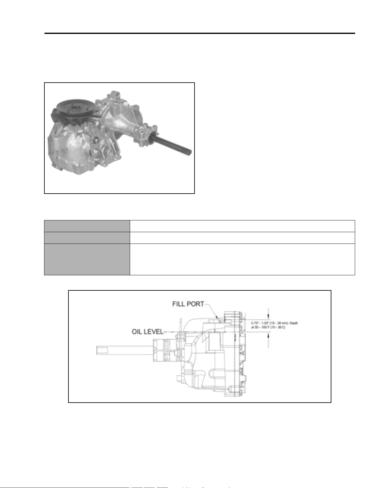
Hydrostatic Transaxle
Identification:
Hydro-Gear Model 330-3000 Transaxle
330-3000
SPECIFICATIONS
General Specifications
Lubrication
Oil Capacity
Oil Level
SAE 20W-50 API Classification SH/CD Oil
3.8 qts. (3.6l)
The transaxle is a sealed system and does not require periodic checking. If the
oil needs to be checked, IT CAN ONLY BE CHECKED COLD. There is a plug
located on the right rear side of the transaxle. Using a ¼ inch Allen wrench,
slowly remove the plug. Oil level should be to the bottom of the port.
400XT Series Tractor Service Manual 1 - 3
Page 10
SPECIFICATIONS
Torque Specifications
Recommended fastener torque values are listed in the
following tables. For critical applications, as determined
by Toro, either the recommended torque or a torque
that is unique to the application is clearly identified and
specified in the service manual.
These torque specifications for the installation and
tightening of fasteners shall apply to all fasteners which
do not have a specific requirement identified in the
service manual. The following factors shall be
considered when applying torque: cleanliness of the
fastener, use of a thread sealant (Loctite), degree of
lubrication on the fastener, presence of a prevailing
torque feature, hardness of the surface underneath of
the fastener’s head, or similar condition which affects
the installation.
As noted in the following tables, torque values should
be reduced by 25% for lubricated fasteners to
achieve the similar stress as a dry fastener. Torque
values may also have to be reduced when the fastener
is threaded into aluminum or brass. The specific torque
value should be determined based on the aluminum or
brass material strength, fastener size, length of thread
engagement, etc.
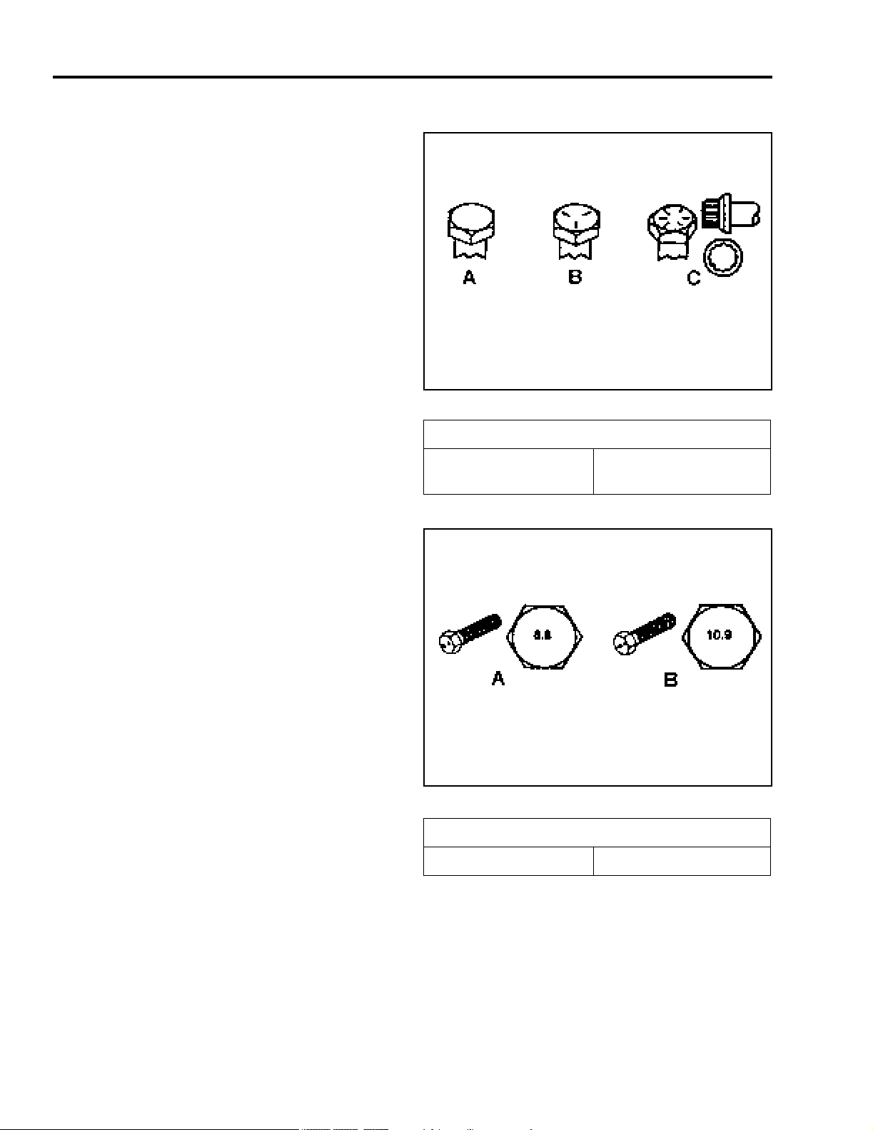
Fastener Identification
Inch Series Bolts and Screws
(A) Grade 1
(B) Grade 5
Figure 1
(C) Grade 8
The standard method of verifying torque shall be
performed by marking a line on the fastener (head or
nut) and mating part, then back off fastener 1/4 of a
turn. Measure the torque required to tighten the
fastener until the lines match up.
Figure 2
Metric Bolts and Screws
(A) Class 8.8 (B) Class 10.9
1 - 4 400XT Series Tractor Service Manual
Page 11

SPECIFICATIONS
Standard Torque for Dry, Zinc Plated, and Steel Fasteners (Inch Series)
Grade 1, 5, &
Thread Size
# 6 - 32 UNC
# 6 - 40 UNF 17 ± 2 190 ± 20 25 ± 2 280 ± 20
# 8 - 32 UNC
# 8 - 36 UNF 31 ± 3 350 ± 30 43 ± 4 31 ± 3
# 10 - 24 UNC
#10 - 32 UNF 48 ± 4 540 ± 45 68 ± 6 765 ± 70
1/4 - 20 UNC 48 ± 7 53 ± 7 599 ± 79 100 ± 10 1125 ± 100 140 ± 15 1580 ± 170
1/4 - 28 UNF 53 ± 7 65 ± 10 734 ± 113 115 ± 10 1300 ± 100 160 ± 15 1800 ± 170
5/16 - 18 UNC 115 ± 15 105 ± 17 1186 ± 169 200 ± 25 2250 ± 280 300 ± 30 3390 ± 340
5/16 - 24 UNF 138 ± 17 128 ± 17 1446 ± 192 225 ± 25 2540 ± 280 325 ± 30 3670 ± 340
3/8 - 16 UNC 16 ± 2 16 ± 2 22 ± 3 30 ± 3 41 ± 4 43 ± 4 58 ± 5
3/8 - 24 UNF 17 ± 2 18 ± 2 24 ± 3 35 ± 3 47 ± 4 50 ± 4 68 ± 5
7/16 - 14 UNC 27 ± 3 27 ± 3 37 ± 4 50 ± 5 68 ± 7 70 ± 7 68 ± 9
7/16 - 20 UNF 29 ± 3 29 ± 3 39 ± 4 55 ± 5 75 ± 7 77 ± 7 104 ± 9
1/2 - 13 UNC 30 ± 3 48 ± 7 65 ± 9 75 ± 8 102 ± 11 105 ± 10 142 ± 14
1/2 - 20 UNF 32 ± 3 53 ± 7 72 ± 9 85 ± 8 115 ± 11 120 ± 10 163 ± 14
5/8 - 11 UNC 65 ± 10 88 ± 12 119 ± 16 150 ± 15 203 ± 20 210 ± 20 285 ± 27
5/8 - 18 UNF 75 ± 10 95 ± 15 129 ± 20 170 ± 15 230 ± 20 240 ± 20 325 ± 27
3/4 - 10 UNC 93 ± 12 140 ± 20 190 ± 27 265 ± 25 359 ± 34 374 ± 35 508 ± 47
3/4 - 16 UNF 115 ± 15 165 ± 25 224 ± 34 300 ± 25 407 ± 34 420 ± 35 569 ± 47
7/8 - 9 UNC 140 ± 20 225 ± 25 305 ± 34 430 ± 45 583 ± 61 600 ± 60 813 ± 81
7/8 - 14 UNF 155 ± 25 260 ± 30 353 ± 41 475 ± 45 644 ± 61 660 ± 60 895 ± 81
8 with Thin
Height Nuts
In-lb In-lb N-cm In-lb N-cm In-lb N-cm
10 ± 2 13 ± 2 147 ± 23
13 ± 2 25 ± 5 282 ± 30
18 ± 2 30 ± 5 339 ± 56
ft-lb ft-lb N-m ft-lb N-m ft-lb N-m
SAE Grade 1 Bolts, Screws,
Studs, & Sems with Regular
Height Nuts (SAE J995
Grade 2 or Stronger Nuts)
SAE Grade 5 Bolts, Screws,
Studs, & Sems with Regular
Height Nuts (SAE J995
Grade 2 or Stronger Nuts)
15 ± 2 170 ± 20 23 ± 2 260 ± 20
29 ± 3 330 ± 30 41 ± 4 460 ± 45
42 ± 4 475 ± 45 60 ± 6 674 ± 70
SAE Grade 8 Bolts, Screws,
Studs, & Sems with Regular
Height Nuts (SAE J995
Grade 2 or Stronger Nuts)
Note: Reduce torque values listed in the table above
by 25% for lubricated fasteners. Lubricated fasteners
are defined as threads coated with a lubricant such as
oil, graphite, or thread sealant such as Loctite.
Note: The nominal torque values listed above for
Grade 5 and 8 fasteners are based on 75% of the
minimum proof load specified in SAE J429. The
tolerance is approximately
value. Thin height nuts include jam nuts.
± 10% of the nominal torque
Note: Torque values may have to be reduced when
installing fasteners into threaded aluminum or brass.
The specific torque value should be determined based
on the fastener size, the aluminum or base material
strength, length of thread engagement, etc.
400XT Series Tractor Service Manual 1 - 5
Page 12

SPECIFICATIONS
Standard Torque for Dry, Zinc, and Steel Fasteners (Metric Fasteners)
Class 8.8 Bolts, Screws, and Studs with
Thread Size
M5 X 0.8 57 ± 5 in-lb 640 ± 60 N-cm 78 ± 7 in-lb 885 ± 80 N-cm
M6 X 1.0 96 ± 9 in-lb 1018 ± 100 N-cm 133 ± 13 in-lb 1500 ± 150 N-cm
M8 X 1.25 19 ± 2 ft-lb 26 ± 3 N-m 27 ± 2 ft-lb 36 ± 3 N-m
M10 X 1.5 38 ± 4 ft-lb 52 ± 5 N-m 53 ± 5 ft-lb 72 ± 7 N-m
M12 X 1.75 66 ± 7 ft-lb 90 ± 10 N-m 92 ± 9 ft-lb 125 ± 12 N-m
M16 X 2.0 166 ± 15 ft-lb 225 ± 20 N-m 229 ± 22 ft-lb 310 ± 30 N-m
M20 X 2.5 325 ± 33 ft-lb 440 ± 45 N-m 450 ± 37 ft-lb 610 ± 50 N-m
Note: Reduce torque values listed in the table above
by 25% for lubricated fasteners. Lubricated fasteners
are defined as threads coated with a lubricant such as
oil, graphite, or thread sealant such as Loctite.
Note: Torque values may have to be reduced when
installing fasteners into threaded aluminum or brass.
The specific torque value should be determined based
on the fastener size, the aluminum or base material
strength, length of thread engagement, etc.
Regular Height Nuts
(Class 8 or Strong Nuts)
Note: The nominal torque values listed above are
based on 75% of the minimum proof load specified in
SAE J1199. The tolerance is approximately
nominal torque value. Thin height nuts include jam nuts.
Class 10.9 Bolts, Screws, and Studs with
Regular Height Nuts (
Class 10 or Strong Nuts)
± 10% of the
1 - 6 400XT Series Tractor Service Manual
Page 13

Other Torque Specifications
SPECIFICATIONS
SAE Grade 8 Steel Set Screws
Recommended Torque
Thread Size
Square Head Hex Socket
1/4 - 20 UNC 140 ± 20 in-lb 73 ± 12 in-lb
5/16 - 18 UNC 215 ± 35 in-lb 145 ± 20 in-lb
3/8 - 16 UNC 35 ± 10 ft-lb 18 ± 3 ft-lb
1/2 - 13 UNC 75 ± 15 ft-lb 50 ± 10 ft-lb
Thread Cutting Screws
(Zinc Plated Steel)
Type 1, Type 23, or Type F
Thread Size Baseline Torque*
No. 6 - 32 UNC 20 ± 5 in-lb
Wheel Bolts and Lug Nuts
Thread Size Recommended Torque**
7/16 - 20 UNF
Grade 5
1/2 - 20 UNF
Grade 5
M12 X 1.25
Class 8.8
M12 X 1.5
Class 8.8
** For steel wheels and non-lubricated fasteners.
Thread
Size
No. 6 18 20 20 ± 5 in-lb
Threads per Inch
Type A Type B
65 ± 10 ft-lb 88 ± 14 N-m
80 ± 10 ft-lb 108 ± 14 N-m
80 ± 10 ft-lb 108 ± 14 N-m
80 ± 10 ft-lb 108 ± 14 N-m
Thread Cutting Screws
(Zinc Plated Steel)
Baseline Torque*
No. 8 - 32 UNC 30 ± 5 in-lb
No.10 - 24 UNC 38 ± 7 in-lb
1/4 - 20 UNC 85 ± 15 in-lb
5/16 - 18 UNC 110 ± 20 in-lb
3/8 - 16 UNC 200 ± 100 in-lb
Conversion Factors
in-lb X 11.2985 - N-cm
ft-lb X 1.3558 = N-m
No. 8 15 18 30 ± 5 in-lb
No. 10 12 16 38 ± 7 in-lb
No. 12 11 14 85 ± 15 in-lb
* Hole size, material strength, material thickness and
finish must be considered when determining specific
torque values. All torque values are based on nonlubricated fasteners.
N-cm X - 0.08851 = in-lb
N-cm X 0.73776 - ft-lb
400XT Series Tractor Service Manual 1 - 7
Page 14

SPECIFICATIONS
Equivalents and Conversions
Decimal and Millimeter Equivalents
Fractions Decimals mm Fractions Decimals mm
1/64 0.015625 0.397 33/64 0.515625 13.097
1/32 0.03125 0.794 16/32 0.53125 13.484
3/64 0.046875 1.191 35/64 0.546875 13.891
1/16 0.0625 1.588 9/16 0.5625 14.288
5/64 0.078125 1.984 37/64 0.578125 14.684
3/32 0.9375 2.381 19/32 0.59375 15.081
1/8 0.1250 3.175 5/8 0.6250 15.875
9/64 0.140625 3.572 41/64 0.640625 16.272
5/32 0.15625 3.969 21/32 0.65625 16.669
11/64 0.171875 4.366 43/64 0.671875 17.066
3/16 0.1875 4.762 11/16 0.6875 17.462
13/64 0.203125 5.159 45/64 0.703125 17.859
7/32 0.21875 5.556 23/32 0.71875 18.256
15/64 0.234375 5.953 47/64 0.734375 18.653
1/4 0.2500 6.350 3/4 0.7500 19.050
17/64 0.265625 6.747 49/64 0.765625 19.447
9/32 0.28125 7.144 25/32 0.78125 19.844
19/64 0.296875 7.541 51/64 0.796875 20.241
5/16 0.3125 7.541 13/16 0.8125 20.638
21/64 0.328125 8.334 53/64 0.828125 21.034
11/32 0.34375 8.731 27/32 0.84375 21.431
23/64 0.359375 9.128 55/64 0.859375 21.828
3/8 0.3750 9.525 7/8 0.8750 22.225
25/64 0.390625 9.922 57/64 0.890625 22.622
13/32 0.40625 10.319 29/32 0.90625 23.019
27/64 0.421875 10.716 59/64 0.921875 23.416
7/16 0.4375 11.112 15/16 0.9375 23.812
29/64 0.453125 11.509 61/64 0.953125 24.209
15/32 0.46875 11.906 31/32 0.96875 24.606
31/64 0.484375 12.303 63/64 0.984375 25.003
1/2 0.5000 12.700 1 1.000 25.400
1 mm = 0.03937 in. 0.001 in. = 0.0254 mm
1 - 8 400XT Series Tractor Service Manual
Page 15

SPECIFICATIONS
U.S. to Metric Conversions
To Convert Into Multiply By
Linear
Measurement
Area
Volume
Weight
Pressure
Work
Liquid Volume
Liquid Flow
Miles
Yards
Feet
Feet
Inches
Inches
Inches
Square Miles
Square Feet
Square Inches
Acre
Cubic Yards
Cubic Feet
Cubic Inches
Tons (Short)
Pounds
Ounces
Pounds/Sq. In. Kilopascal 6.895
Foot-pounds
Foot-pounds
Inch-pounds
Quarts
Gallons
Gallons/Minute Liters/Minute 3.785
Kilometers
Meters
Meters
Centimeters
Meters
Centimeters
Millimeters
Square Kilometers
Square Meters
Square Centimeters
Hectare
Cubic Meters
Cubic Meters
Cubic Centimeters
Metric Tons
Kilograms
Grams
Newton-Meters
Kilogram-Meters
Kilogram-Centimeters
Liters
Liters
1.609
0.9144
0.3048
30.48
0.0254
2.54
25.4
2.59
0.0929
6.452
0.4047
0.7646
0.02832
16.39
0.9078
0.4536
28.3495
1.356
0.1383
1.152144
0.9463
3.785
Temperature
Fahrenheit Celsius 1. Subtract 32°
2. Multiply by 5/9
400XT Series Tractor Service Manual 1 - 9
Page 16

THIS PAGE INTENTIONALLY LEFT BLANK
1 - 10 400XT Series Tractor Service Manual
Page 17
CHASSIS
Model and Serial Number Location
The model and serial number plate location is under
the seat (Figure 3).
Figure 3
MVC-742
Greasing and Lubrication
3. One located on the front axle pivot area (1 total)
(Figure 4).
Figure 4
4. NOTE: On 2004 models, there is a grease zerk
located on the forward/reverse pedal.
MVC-746
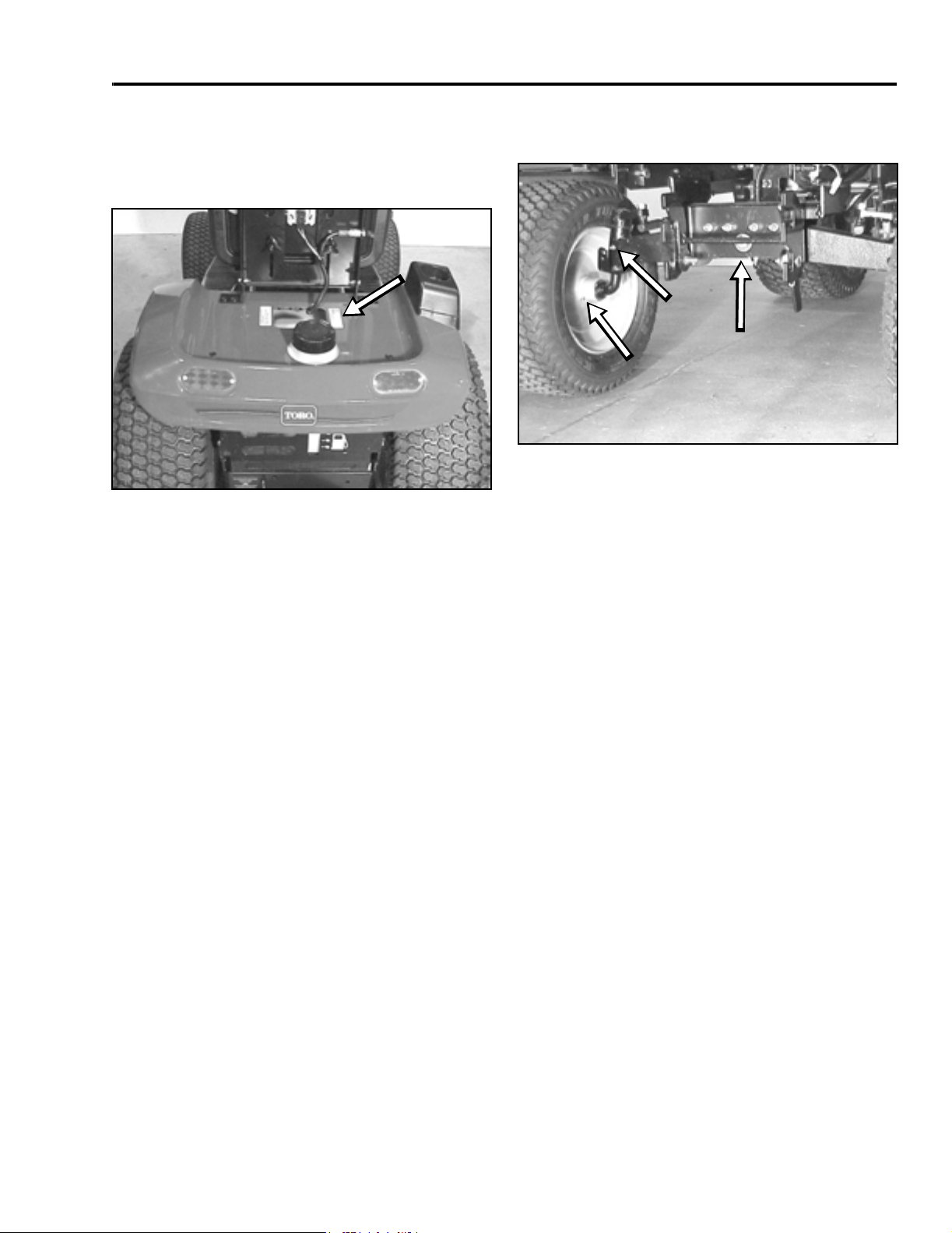
Front Wheel Toe-in
The machine should be greased every 50 hours or
yearly, whichever occurs first. You should grease more
frequently when operating conditions are extremely
dusty or sandy.
Grease Type: General-purpose grease.
There are 5 grease fittings located in the front axle
area:
1. One located on the inside of each wheel hub (2
total).
2. One located on each end of the front axle for the
spindles (2 total).
If there is uneven tire wear, lawn scuffing, or hard
steering, toe-in may need to be adjusted. The front
toe-in measurement should be 1/8” to ¼” (3 to 6mm).
This should be checked every 100 hours or once a
year, whichever occurs first.
MEASUREMENT:
1. Disengage the PTO, set the parking brake, and
turn the ignition key to OFF to stop the engine.
Remove the key.
400XT Series Tractor Service Manual 2 - 1
Page 18
CHASSIS
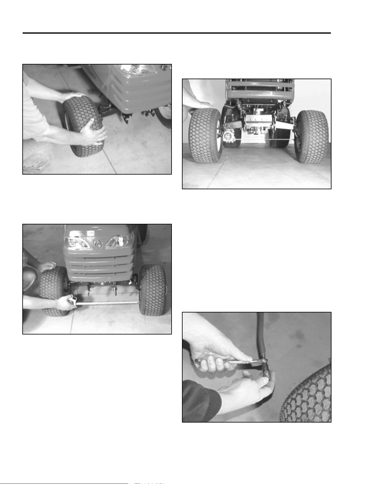
2. Push the front of the tires out to remove normal
looseness in the linkage (Figure 5).
Figure 5
3. Measure the distance between both the front rims
at spindle level, in front and rear of the wheels.
You can also measure between the tread mold
marks if the tires are new (Figure 6).
MVC-747
4. The front measurement should be 1/8” to ¼”
(3mm to 6mm) less than the rear measurement
(Figure 7). If needed, follow the adjustment
procedure.
Figure 7
MVC-752
Front Wheel Toe-in Adjustment
Figure 6
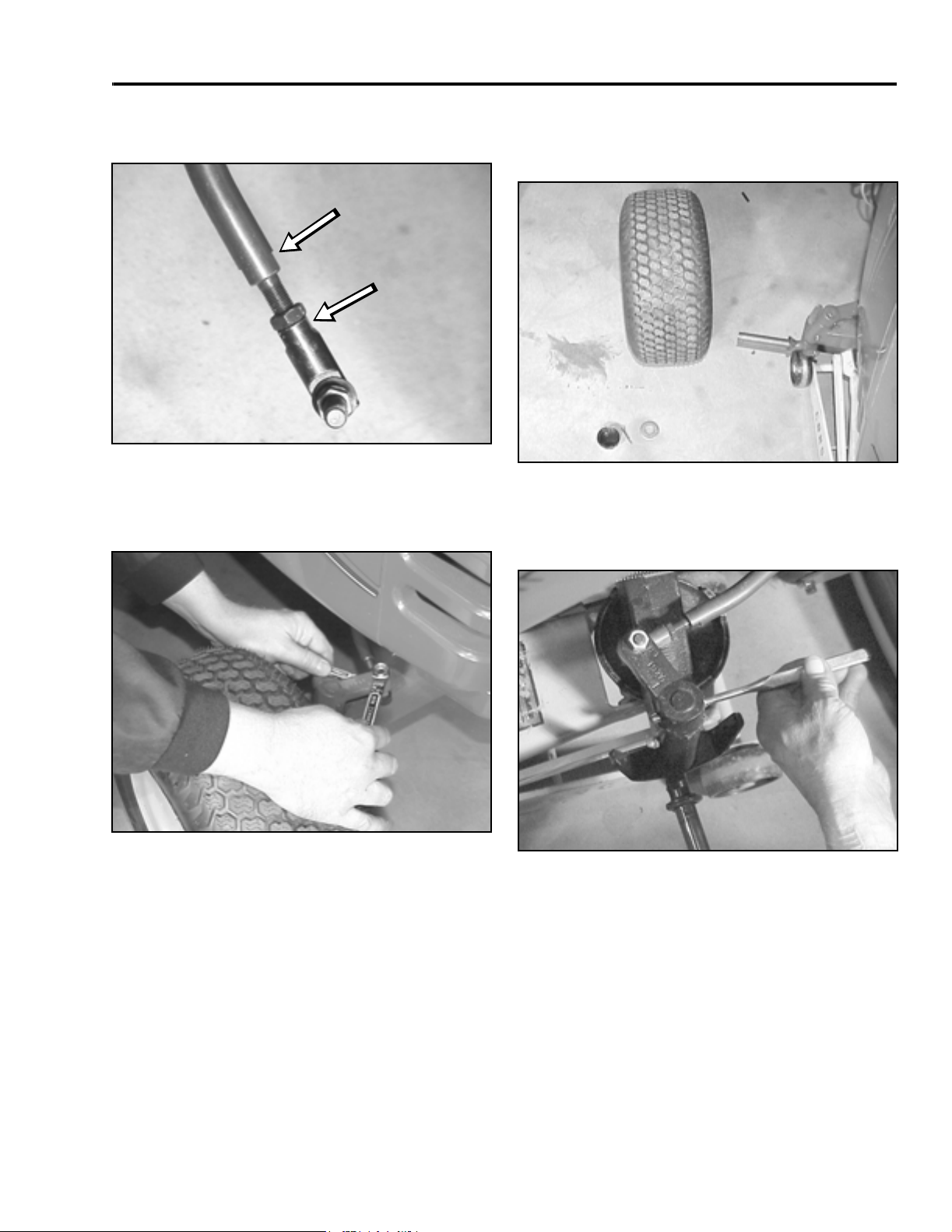
1. Remove the tie rod from one steering arm.
2. Loosen the jam nut securing the ball joint to the
steering rod. Rotate the ball joint one turn:
clockwise to increase toe-in; counterclockwise to
decrease toe-in (Figure 8).
IMPORTANT: If more than one turn is required
to meet specifications, alternate between the
right and left steering rods to maintain
steering wheel alignment.
MVC-749
Figure 8
2 - 2 400XT Series Tractor Service Manual
MVC-095X
Page 19
CHASSIS
3. Hold the flats on the ball joint to align with the flats
on the tie rod and tighten the jam nut (Figure 9).
Figure 9
4. Install the ball joint to the steering arm and check
the toe-in as described in the measurement
section (Figure 10).
MVC-098X
3. Remove the outer hub cap, cotter pin, washer,
and hub cap washer. Slide the wheel and tire off
the spindle (Figure 11).
Figure 11
4. Remove the tie rod from the front spindle arm.
With a drift punch and hammer, drive the roll pin
out of the front spindle arm (Figure 12).
MVC-100X
Figure 10
MVC-099X
Figure 12
MVC-732X
Front Wheel and Spindle Removal
and Installation
Removal
1. Disengage the PTO. Set the parking brake, and
turn the ignition key to OFF to stop the engine.
Remove the key.
2. Raise the front axle by putting a jack under the
side you are removing the wheel or spindle from.
400XT Series Tractor Service Manual 2 - 3
Page 20
CHASSIS
5. The spindle can now be removed out the bottom
of the front axle assembly (Figure 13).
Figure 13
6. Installation – reverse the order of removal.
MVC-102X
Front Axle Removal and Installation
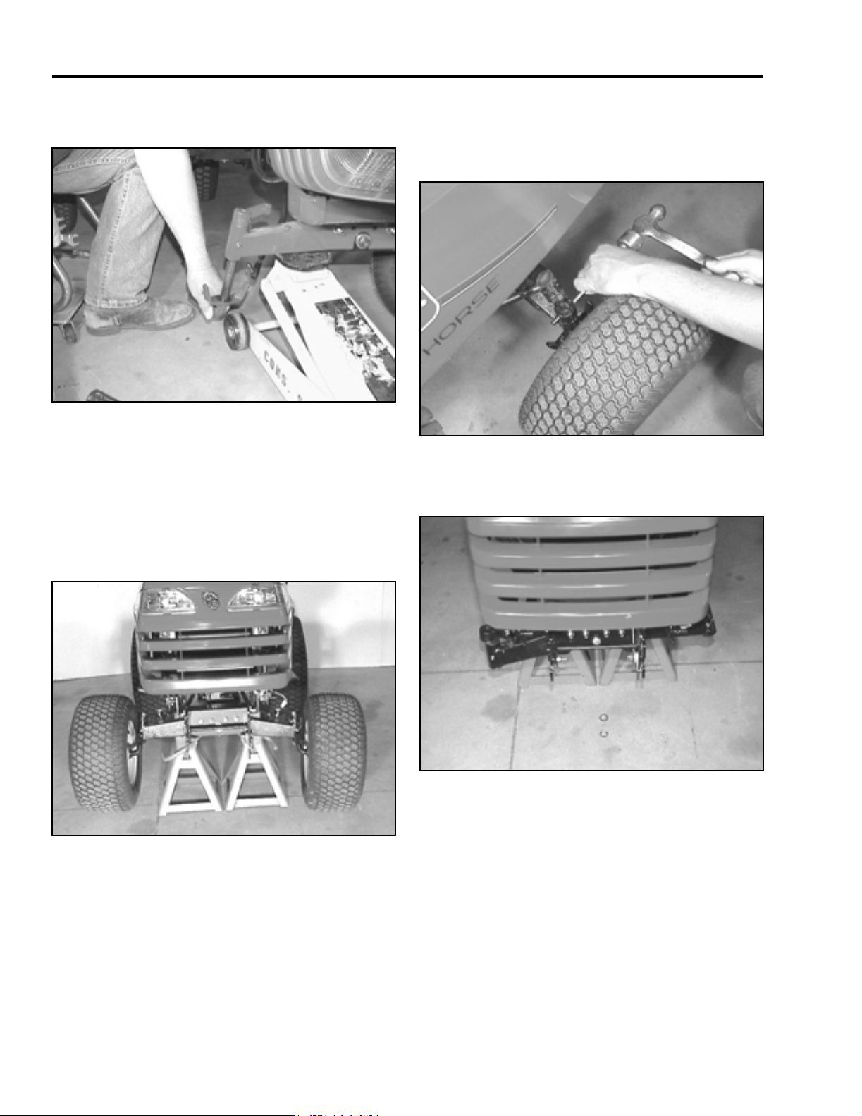
2. Using a drift punch and hammer, drive the roll pin
out of the front spindle arms and remove the arms
from the spindles (Figure 15). Remove the wheels
with steering spindles, from the axle.
Figure 15
3. On the front of the axle, in the center, remove the
E-ring and washers (Figure 16).
MVC-757
1. Jack-up the front of the tractor. Put jack stands
under the frame, just behind the front axle
assembly (Figure 14).
Figure 14
MVC-756
Figure 16
MVC-758
2 - 4 400XT Series Tractor Service Manual
Page 21
CHASSIS
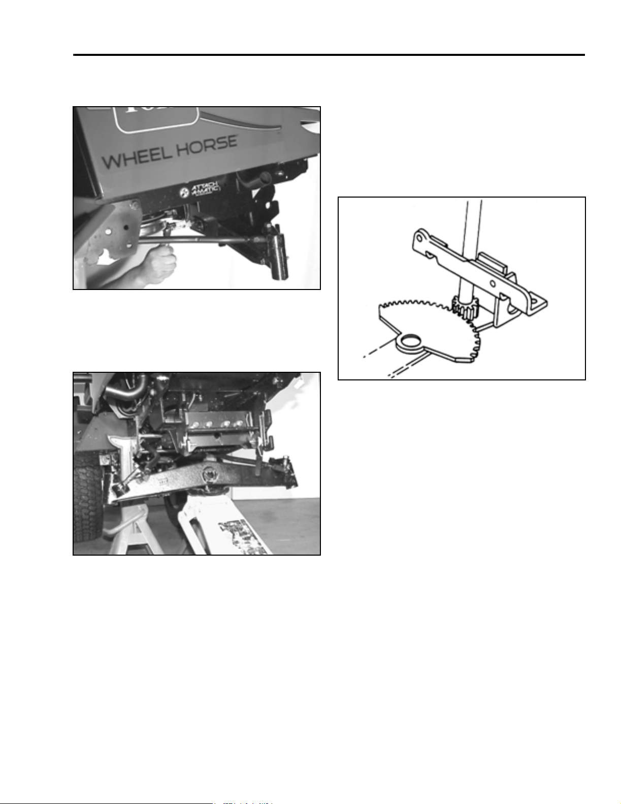
4. On the back side of the axle assembly, remove the
bolt securing the axle pin (Figure 17).
Figure 17
5. Remove the axle pin; use a drift punch and
hammer to tap the axle pin out; if needed. Lower
the axle assembly out of the tractor frame (Figure
18).
mvc-761
Steering Gear
Description
The steering gear assembly is made up of a vertically
mounted steering shaft and a horizontal sector gear.
The sector gear is adjustable so that excessive
backlash play in steering gears can be removed
(Figure 19).
Figure 18
6. Installation - reverse the order of removal.
MVC-763
Figure 19
6-8
Steering Backlash Adjustment
Use the following procedure if there is excessive
steering backlash.
1. Remove battery and battery tray from the tractor.
400XT Series Tractor Service Manual 2 - 5
Page 22

CHASSIS
2. Disconnect the right and left tie rod assemblies
(Figure 20).
Figure 20
MVC-099X
3. Loosen the locking nut on the eccentric. Position
the steering wheel spokes so they extend outward
left to right.
4. Tighten the nut until the eccentric turns with a
small amount of friction (Figure 21).
5. Using a punch, turn the eccentric clockwise until
zero clearance is obtained between the end of the
steering shaft gear and the steering sector (Figure
22).
Figure 22
MVC-113X
6. Tighten the nut to 25 – 35 ft lb (34 – 48 Nm). DO
NOT OVERTIGHTEN.
7. Apply some multipurpose grease to the steering
gear teeth.
Figure 21
MVC-110X
8. Connect the tie rod ends to the steering arms.
9. Turn the wheels left and right. Recheck for zero
clearance (Figure 23).
Figure 23
MVC-115X
10. Reinstall the battery tray and battery.
11. Check wheel alignment and toe-in.
2 - 6 400XT Series Tractor Service Manual
Page 23

CHASSIS
Steering Gear Shaft Disassembly
1. Disconnect the battery cables. Remove the right
side plate and battery from the tractor.
2. Remove the center steering wheel cover.
Remove the nut, lock washer, and pull the
steering wheel off the steering shaft (Figure 24).
4. Rotate the steering shaft until the top bolt of the
universal joint faces the rear of the tractor.
Remove the bolt (Figure 26).
Figure 26
5. Pull the top shaft from the universal joint and
remove it from the top of the tractor (Figure 27).
MVC-729X
Figure 24
3. Remove the boot clip from the inside of the dash
and remove the rubber boot from the steering
shaft console (Figure 25).
Figure 25
MVC-765
MVC-766
Figure 27
6-12
400XT Series Tractor Service Manual 2 - 7
Page 24

CHASSIS
6. Rotate the steering gear shaft until the bottom bolt
of the universal joint faces the front of the tractor.
Remove the bolt (Figure 28).
Figure 28
6-14
7. Tilt steering to the rear position and remove the
universal joint from the steering shaft gear.
Remove the universal joint from the top of the
tractor (Figure 29).
8. Expand the snap ring found on the steering gear
shaft and slide if halfway down the shaft. Loosen
the setscrew on the locking collar of the steering
gear shaft and move it until it meets the snap ring
(Figure 30).
Figure 30
6-16
9. Lift the steering shaft upwards, out of the lower
bushing and through the opening in the mounting
bracket. Tilt the shaft towards the front of the
tractor and remove it (Figure 31).
Figure 29
6-15
Figure 31
6-17
2 - 8 400XT Series Tractor Service Manual
Page 25

CHASSIS
10. Remove the shims from the top of the lower
bushing and set aside for installation process
(Figure 32). Important: Check the bushing,
shaft, and gears for wear and replace with new
parts if necessary. Refer to “Steering
Specifications” on page 2 - 14.
Figure 32
11. Installation - reverse the order of removal.
Steering Gear Assembly
6-16
Figure 33 6-19
(1) Shims
(2) Lower Bushing
(3) Steering Gear Shaft
1. Place two 0.05” (1.27mm) shims,1, between the
top of the bushing, 2, and the steering gear shaft,
3.
Note: Lubricate the bushing with general
purpose grease during assembly.
2. Align the front wheels so that they face straight
ahead.
3. Install snap ring, 4; locking collar, 5; and upper
bushing, 6, onto the steering gear shaft.
4. Insert the steering gear shaft through the opening
in the mounting bracket and onto the lower
bushing.
Note: The shims must be in place.
(4) Snap Ring
(5) Locking Collar
(6) Mid Bushing
400XT Series Tractor Service Manual 2 - 9
Page 26

CHASSIS
5. Move the locking collar upward on the shaft until it
touches the column support mid bushing. Tighten
the collar set screw, then move the snap ring
upward on the shaft until it meets the bottom of
the locking collar (Figure 33).
5
3
3
4
1
2
Figure 34
(1) Universal Joint
(2) Lower Steering Gear
Shaft
(3) Retaining Bolts
(4) Upper Steering
Shaft
(5) Steering Bushing
6-22
8. Install the rubber boot over the steering shaft and
console with a boot clip (Figure 35).
Figure 35
9. Place the steering wheel on the steering shaft and
install the lock washer and nut. Reinstall the
steering wheel cover.
Important: Ensure that all hardware is securely
fastened that the steering wheel is centered when
the wheels are straight ahead, and that the
steering operates properly.
MVC-766
6. Tilt steering to the rear position and place the
universal joint,1, onto the top end of the lower
steering gear shaft, 2. Install the retaining bolt, 3,
of the universal joint through the joint and steering
gear shaft.
7. Place upper steering shaft, 5, onto the upper end
of the universal joint,1. Install the retaining bolt 3,
through the upper end of the universal joint and
upper steering.
Note: Ensure that electrical wiring can not come
into contact with upper steering shaft of universal
joint in any position.
Note: Ensure that electrical wiring can not come
into contact with upper steering shaft of universal
joint in any position.
2 - 10 400XT Series Tractor Service Manual
Page 27

CHASSIS
Sector Gear Disassembly
1. Remove the battery and battery bracket from the
tractor. Disconnect both steering tie rods from the
sector gear. Using the access hole in the
mounting bracket, remove the lock nut and
carriage bolt holding the sector in place (Figure
36).
Figure 36
6-25
Sector Gear Assembly
Figure 38 6-28
(1) Washer Bearing
(2) Sector Gear
(3) Bushing
1. Install the bearing washer, 1, on the mounting
bracket (Figure 38).
(4) Locking Plate
(5) Carriage Bolt
(6) Locknut
2. Remove the locking plate from the top of the
sector gear (Figure 37).
Figure 37
3. Remove the cam bushing, 3, and the sector gear,
2, from the mounting bracket (Figure 38).
Important: Inspect the sector gear teeth and cam
bushing for wear and replace if necessary.
6-26
2. Place the sector gear, 2, on top of the bearing
washer with the teeth facing the rear of the tractor
(Figure 38).
3. Ensure the steering wheel is centered, then center
the steering shaft with the sector gear (Figure 39).
Figure 39
6-8
400XT Series Tractor Service Manual 2 - 11
Page 28

CHASSIS
4. Insert the cam bushing, 3, into the bore of the
sector gear (Figure 38).
5. Place the locking plate, 4, on the cam bushing
(Figure 38).
6. From the bottom, insert the carriage bolt, 5,
through the bearing washer, cam bushing, and the
locking plate. Secure the bolt with the locknut, 6
(Figure 38).
7. Adjust the steering gear, refer to “Steering
Backlash Adjustment” on page 2 - 5.
8. Fasten both steering arms onto the sector gear.
Check wheel alignment and toe-in.
NOTE: On 2004 models and on new replacement
steering sector gears, make sure the angle of the
teeth are facing down.
Tilt Steering
Figure 40 6-34
Description
The tilt steering assembly is made up of the following
components (Figure 40):
1. Universal joint.
2. Steering column (bushing mounted).
3. Detent bracket (left side).
4. Support bracket (right side).
5. Spring-loaded control handle.
(1) Retaining Bolt
(2) Universal Joint
(3) Retaining Bolt
(4) Upper Steering
Shaft
(5) Spring Extension
(6) Bolts
(7) Detent Bracket
(8) Support Bracket
(9) Retaining Bolt
(10) Spacer-Yoke
(11) Column
(12) Tilt Lever
(13) Steering Bushing
Figure 41 6-35
2 - 12 400XT Series Tractor Service Manual
Page 29

CHASSIS
Tilt Steering Disassembly
1. Remove the steering wheel cover, nut, lock
washer, and steering wheel from top of the
steering shaft (Figure 42).
Figure 42
2. Remove the boot clip, from the inside of the dash
and remove the rubber boot from the steering
console (Figure 43).
Mvc-765
6. Remove the spring, 5, from the left pivot spacer
and tilt control handle (Figure 41).
7. Remove the four bolts, 6, and nuts from the left
and right support brackets, 8, and 9, and remove
the brackets (Figure 41).
8. Remove the two side pivot bolts, 9, and spacers,
10, from the steering column. Lift the column, 11,
out of the tractor (Figure 41).
9. Slide the tilt control handle, 12, off the steering
column bracket (Figure 41).
10. Remove the bushing, 13, from the top of the
steering column (Figure 41).
Important: Inspect all bushings and pivot areas
for wear and replace as necessary. Refer to
“Steering Specifications” on page 2 - 14.
Tilt Steering Assembly
1. Place bushing, 13, on top of the steering column
(Figure 41).
Figure 43
3. Remove the bottom retaining bolt, 1, from the
universal joint, 2 (Figure 41).
4. Remove the top retaining bolt, 3, from the
universal joint and disconnect the top steering
shaft, 4, from the tractor (Figure 41).
5. Tilt steering to the rear position and detach the
universal joint from the steering gear shaft. Take
the universal out of the tractor from the top side.
MVC-766
2. Insert the tilt control handle, 12, into the steering
column bracket (Figure 41).
3. Secure the steering column to the mounting
bracket with pivot bolts, 9; spacers, 10; and
locknuts (Figure 41).
Note: The longer spacers should be positioned
on the left-hand side.
4. Install the left, 7, and right, 8, support brackets,
using four bolts, 6, and nuts. The notched bracket
goes on the left side. Adjust the brackets to obtain
minimal side play between the column and
brackets (Figure 41).
5. Attach the spring, 5, to the tilt handle and left pivot
spacers (Figure 41).
6. Tilt steering to its farthest rearward position and
place the universal joint, 2, on the steering gear
shaft. Pass the bottom bolt, 1, of the universal
joint through the universal and steering gear shaft
and secure (Figure 41).
400XT Series Tractor Service Manual 2 - 13
Page 30

CHASSIS
7. Insert the top steering shaft, 4, onto the upper end
of the universal joint check the front wheel
alignment, wheels should be straight ahead.
Install the retaining bolt, 3, through the upper end
of the universal joint and steering shaft (Figure
41).
Note: Ensure electrical wiring can not come into
contact with upper steering shaft or universal joint
in any position.
8. Install the rubber boot over the steering shaft and
secure the boot to console with the rubber clip
(Figure 44).
9. Align the steering wheel on the steering shaft.
Secure the steering wheel with lock washer and
nut. Install steering wheel cover (Figure 45).
Figure 45
MVC-765
Figure 44
MVC-766
Steering Specifications
Item Specification
Free Play – front axle pivot pin 0 – 0.015” (0 – 0.4mm)
End Play – front wheel on spindle 0 – 0.015” (0 – 0.4mm)
Toe-In 1/8” – ¼” (3 – 6mm)
Steering Wheel Free Play (Backlash) 0.5” – 1.0” (13 – 25mm)
Steering Shaft Bushings (standard dimensions)
Top (Fiber) ID 0.752 – 0.756” (19.1 – 19.2mm)
OD 1.310 – 1.320” (33.3 – 33.5mm)
Mid (Metal) ID 0.755 – 0.760” (19.2 – 19.3mm)
OD 0.988 – 1.00” (25.3 – 25.4mm)
Bottom (Metal) ID 0.753 – 0.758” (19.1 – 19.2mm)
OD 1.380 – 1.385” (35.0 – 35.2mm)
2 - 14 400XT Series Tractor Service Manual
Page 31

CHASSIS
Hood Removal
1. Disconnect the headlight wiring harness at the
plug and jack connection (Figure 46).
Figure 46
2. On 2003 model units, remove the rubber O-ring,
located on the left side hinge bracket, and raise
the hood. Slide the hood to the left and off the
hinge brackets. (Figure 47).
MVC-003
3. On 2004 and later model units, raise the hood in
the full up position, then bring the hood back
slightly and slide the hood toward the left side of
the tractor (Figure 48).
Figure 48
4. Reinstall the hood in reverse order.
MVC-015
Seat and Fender Removal
Figure 47
MVC-018
1. Unplug the seat switch, and the KeyChoice™
Reverse operating switch (Figure 49).
Figure 49
2. To make it easier to remove the fasteners for the
fender assembly, jack the tractor up in the rear
and remove both rear tires.
MVC-865F
400XT Series Tractor Service Manual 2 - 15
Page 32

CHASSIS
3. Remove the two rear carriage bolts, washers, and
nuts located in the rear of the fender assembly
(Figure 50).
Figure 50
4. Remove the four carriage bolts, washers, and
nuts, (two on the right and two on the left), located
between the footrest and fender (Figure 51).
MVC-122X
5. Remove the seat and fender together as one
piece (Figure 52).
Figure 52
6. Installation - follow the removal procedure in
reverse.
MVC-029
Gas Tank Removal
Figure 51
MVC-012
1. Follow the procedure for removing the rear fender
and seat.
2. Remove the two screws and spacers in the front
of the gas tank (Figure 53).
Figure 53
MVC-129X
2 - 16 400XT Series Tractor Service Manual
Page 33

CHASSIS
3. Lift the gas tank from the frame, close the gas
shut-off valve, and disconnect the gas line from
the shut-off valve (Figure 54).
Figure 54
4. Carefully remove the gas tank.
Installation
MVC-130X
2. Remove the right and left washers and e-rings
located on each end of the lift bar assembly
(Figure 56).
Figure 56
3. Slide the lift bar out of the flange bushings and the
rear lift plates (Figure 57).
MVC-800F
Reverse the order of removal.
Lift Bar Assembly
Removal
1. Remove the bolt, washer, and nut retaining the lift
chain to the lift bar (Figure 55).
Figure 57
MVC-803F
Figure 55
400XT Series Tractor Service Manual 2 - 17
MVC-798F
Page 34

CHASSIS
Lift Lever Assembly
Removal
1. Remove the center access plate. Remove the pin
clip and clevis pin retaining the two lift strap links
to the lift lever (Figure 58).
Figure 58
MVC-804F
3. Slide the right and left flange bearings inward from
the pivot linkage brackets, so you will have
enough clearance to remove the lift lever
assembly (Figure 60).
Figure 60
4. Remove the lift lever assembly from the pivot
linkage brackets (Figure 61).
MVC-807F
2. Remove the two retaining rings that are located on
each side of the lift lever assembly (Figure 59).
Figure 59
MVC-806F
Figure 61
Assembly
Reverse the order of removal.
MVC-809F
2 - 18 400XT Series Tractor Service Manual
Page 35

CHASSIS
Lift Arm/Lift Lever Assembly
Removal
1. Remove the right and left side panels. Remove
the center access plate. Disconnect the battery
cables and remove the battery from the tractor.
2. Remove the two bolts holding the battery support
and remove the support (Figure 62).
4. Pull the dash upwards, with the steering shaft, and
move carefully toward the front of the tractor to
give you enough clearance to get to the lift
assembly (Figure 64).
Figure 64
5. Remove the six bolts, three located on the right
and three on the left side, inside of the hood stand
(Figure 65).
MVC-820F
Figure 62
3. Remove the 4 screws and 2 nuts from the base of
the dash. Remove the bolt and nut located in the
center of the hood stand, just below the large
decal (Figure 63).
Figure 63
MVC-815F
MVC-817F
Figure 65
MVC-821F
400XT Series Tractor Service Manual 2 - 19
Page 36

CHASSIS
6. Remove spring for the brake assembly (Figure
66).
Figure 66
7. Lift the hood stand off the frame of the tractor
(Figure 67).
MVC-822F
8. Lift the lift assembly up and off the frame of the
tractor (Figure 68).
Figure 68
Installation
Reverse the order of removal.
MVC-826F
Figure 67
2 - 20 400XT Series Tractor Service Manual
MVC-827F
Page 37

Electric Lift
CHASSIS
Figure 69 Eleclift
(1) Actuator
(2) Spacer
(3) Clevis Pin
(4) Clip Pin
Removal
1. Remove the right and left hood stand panels to the
battery compartment.
2. Disconnect the negative and positive cables from
the battery.
3. Remove the two screws holding the battery
support and remove the support.
4. Unplug the actuator, 1, from the wiring harness.
5. Remove the clip pin, 4, and clevis pin, 6, that
holds the actuator, 1, to the actuator bracket
assembly, 7.
(5) Washer
(6) Clevis Pin
(7) Actuator Bracket Assembly
(8) Lift Arm Assembly
6. Remove the clip pin, 4, spacers, 2, washers, 5,
and clevis pin, 3, from the lift arm assembly, (8).
7. Remove the actuator, 1, from the tractor. The
actuator is serviced as an assembly; no repair
parts are available.
8. Remove the actuator
Installation
Reverse the order of removal.
400XT Series Tractor Service Manual 2 - 21
Page 38

THIS PAGE INTENTIONALLY LEFT BLANK
2 - 22 400XT Series Tractor Service Manual
Page 39

HYDRO-GEAR TRANSAXLE
Hydro-Gear Hydrostatic Transaxle
Internal Service
Internal service information is contained in the HydroGear Transaxle Service Manual, Form #492-0682.
Under warranty, internal service work should not be
performed unless authorized by your Distributor
Service Manager or the Toro Company.
Fluid Change
The Hydro-Gear transaxle is factory filled, sealed, and
does not require oil changes. However in the event of
oil contamination or degradation, oil replacement may
correct certain performance problems.
Transaxle Removal
1. Disconnect the negative battery cable from the
battery.
3. Disconnect the free wheeling valve I rod and the
vent hose clamp (Figure 118).
Figure 118
4. Remove the cotter pin located on the crown nut for
adjusting the brakes. Remove the crown nut,
brake bracket, brake arm spring and brake rod
(Figure 119).
MVC-060F
2. Raise the rear of the tractor and remove the right
and left rear tires. Support the rear frame, just in
front of the transaxle. Remove the center access
plate, fender, seat, and gas tank. Refer to the
“Chassis” section on page 2 - 15 and page 2 - 16.
Remove the center plate between the seat and
the hood stand (Figure 117).
Figure 117
MVC-061F
Figure 119
MVC-063F
400XT Series Tractor Service Manual 3 - 1
Page 40

HYDRO-GEAR TRANSAXLE
5. If the tractor is equipped with cruise control,
unplug the cruise control magnet wiring
connectors (Figure 120).
Figure 120
MVC-064F
6. Unbolt the cruise control magnet bracket from the
side of the frame (Figure 121).
7. Unhook the idler spring from the bottom of the
idler pulley (Figure 122).
Figure 122
MVC-066F
8. Remove the three bolts retaining the transmission
fan to the pulley (Figure 123).
MVC-067C
Figure 121
Figure 123
MVC-065F
3 - 2 400XT Series Tractor Service Manual
Page 41

HYDRO-GEAR TRANSAXLE
9. Remove the damper cylinder located next to the
transaxle input pulley. To remove the fastener on
the end of the cylinder, insert the blade of a
screwdriver between the back side of the fastener
and the shaft. Apply a little pressure toward the
back of the fastener and pull the damper cylinder
off the shaft (Figure 124).
Figure 124
MVC-070F
11. Use a floor jack under the transaxle to help lower
the transaxle from the frame of the tractor (Figure
126).
Figure 126
MVC-073
12. Remove the bolt, washer, and nut retaining the
torque strap to the transaxle, located on the left
front side (Figure 127).
10. Slip the belt off the transaxle input pulley (Figure
125).
Figure 125
MVC-171X
Figure 127
MVC-072F
400XT Series Tractor Service Manual 3 - 3
Page 42

HYDRO-GEAR TRANSAXLE
13. Remove the two nuts and washers that are
located on each side of the transaxle axle housing
holding the transaxle to the frame (Figure 128).
Figure 128
MVC-073F
14. Slowly lower the transaxle slightly and STOP. You
will need to disconnect the hydro rod from the
cruise control plate. Remove the cotter pin and
washer (Figure 129).
15. Continue to lower the transaxle out of the tractor
frame (Figure 130).
Figure 130
MVC-077F
Installation - Hydro-Gear Transaxle
1. Raise the transaxle up toward the frame allowing
enough room to install the hydro rod to the cruise
plate and secure with a cotter pin and washer
(Figure 129).
Figure 129
MVC-074F
2. Secure the transaxle to the frame brackets with
four carriage bolts, washers, and nuts (Figure
131).
Figure 131
MVC-078F
3 - 4 400XT Series Tractor Service Manual
Page 43

HYDRO-GEAR TRANSAXLE
3. Install the bolt, washer, and nut through the front
of the transaxle to the torque strap (Figure 132).
Figure 132
MVC-072F
4. Install the drive belt around the transaxle input
pulley. Install the idler spring on the idler pulley
(Figure 133).
5. Connect the damper cylinder to the control linkage
(Figure 134).
Figure 134
MVC-080F
6. Install the three bolts to secure the transaxle
cooling fan to the transaxle pulley (Figure 135).
MVC-067
Figure 133
Figure 135
MVC-066F
400XT Series Tractor Service Manual 3 - 5
Page 44

HYDRO-GEAR TRANSAXLE
7. Install the cruise control bracket, with magnet, with
two bolts and nuts (Figure 136).
Figure 136
MVC-065
8. Reconnect the wire connector for the magnet
(Figure 137).
9. Install the brake arm with the brake spring, on the
brake stud. Install the castle nut, but do not install
the cotter pin until brake adjustment has been
performed (Figure 138). Refer to “Brake
Adjustment” on page 3 - 9.
Figure 138
MVC-063
10. Connect the free wheeling valve rod and vent
hose clamp (Figure 139).
Figure 137
MVC-064
Figure 139
MVC-060
3 - 6 400XT Series Tractor Service Manual
Page 45

HYDRO-GEAR TRANSAXLE
11. Reconnect the gas line to the gas tank and install
the gas tank with two screws and washers (Figure
140).
Figure 140
NOTE: When installing a new transaxle in the
machine or if any work was performed internally
on the transaxle, make sure the system is purged
prior to doing any neutral adjustment. Refer to
“Neutral Adjustment” on page 3 - 7.
MVC-081F
Neutral Adjustment
Before making a neutral adjustment, the transaxle
must be warmed up, usually 5 to 10 minutes. Steps to
perform neutral adjustment:
1. Jack-up and support the right rear end of the
tractor, allowing enough clearance to remove the
right rear tire. Make sure the left tire stays on the
ground (Figure 141). (Optional: remove the
fender and seat assembly. If they are removed,
you will need to temporarily bypass the seat
switch.)
12. Reconnect the negative battery cable.
13. Attach a jumper wire across the seat switch plug
terminals so the tractor will run without an
operator in the seat. Test to confirm proper
operation of the transaxle. If adjustment is
needed, refer to “Neutral Adjustment” on page 3 -
7.
14. Install fender and seat assembly and the center
access plate. Install the right tire.
15. Operate the tractor and make sure all safety
features are working. Check the forward and
reverse operation of the tractor. If you find there is
not enough speed in reverse or forward, follow the
adjustment procedures for the foot control; refer to
“Foot Control Adjustment” on page 3 - 10.
Figure 141
2. Locate the adjusting puck and loosen the Allen
head set screw (Figure 142).
Figure 142
MVC-161X
1703-07
3. Start the engine and run at 3/4 to full throttle.
400XT Series Tractor Service Manual 3 - 7
Page 46

HYDRO-GEAR TRANSAXLE
4. Rotate the adjusting puck in both directions and
watch the axle direction. You want to adjust the
puck so it is set in the mid-point between forward
and reverse axle rotation. Make sure the axle is
not moving (Figure 143).
Figure 143
5. Once you are in neutral, hold the puck with an
adjustable wrench so it won’t move when you retighten the Allen set screw (Figure 144).
1703-08
Transaxle Purging Procedures
Due to the effects air has on efficiency in hydrostatic
drive applications, it is critical that it be purged from the
system.
These purge procedures should be implemented any
time oil has been added to the system, when a new
transaxle is installed, or after a transaxle has been
repaired.
Air creates inefficiency because its compression and
expansion rate is higher than that of the oil normally
approved for use in hydrostatic drive systems.
The resulting symptoms in hydrostatic systems may
be:
1. Noisy operation.
2. Lack of power or drive after short term of
operation.
3. High operation temperature and excessive
expansion of “oil”; in the latter case, oil may
overflow.
Figure 144
6. Operate the foot control in forward and reverse
and allow the pedal to return to the neutral
position to test the adjustment.
NOTE: You may not be able to eliminate creep
entirely, due to the narrow neutral zone of this
transaxle. In this case, adjust for the smallest amount
of reverse creep possible. Correctly adjusted, a very
light tap on the foot control pedal should be all that is
needed to stop the reverse creep.
MVC-226X
Before starting, make sure the transaxle is at the
specified oil level; refer to page 1 - 3.
The following procedures should be performed with the
vehicle drive wheels off the ground, then repeated
under normal operating conditions.
1. With the bypass valve open and the engine
running, slowly move the directional control (foot
control) in both forward and reverse directions 5 to
6 times; as air is purged from the unit, the oil level
will drop.
2. With the bypass valve in the closed position and
the engine running, slowly move the directional
control valve (foot control) in both forward and
reverse directions 5 to 6 times. After stopping the
engine, check the oil level and add oil as required.
3. It may be necessary to repeat steps 1 and 2 until
all the air is completely purged from the system.
When the transaxle moves forward and reverse at
normal speed, purging is complete.
3 - 8 400XT Series Tractor Service Manual
Page 47

HYDRO-GEAR TRANSAXLE
CAUTION – DO NOT OVERFILL. If you overfill the
transaxle while the unit is “cold”, it may overflow as it
reaches normal operating temperatures. The oil level
should not be above the level described on page 1 - 3.
This will allow the space needed for the oil to expand
as it warms up.
Brake
Always set the parking brake when you stop the
machine or leave it unattended. If the parking brake
does not hold securely, an adjustment is required.
Checking the Brake
1. Park the machine on a level surface, disengage
the power take off (PTO), set the parking brake,
and turn the ignition key to “OFF” to stop the
engine. Remove the ignition key.
2. Rear wheels must lock and skid when you try to
push the tractor forward. Adjustment is required if
the wheels turn and do not lock; refer to “Brake
Adjustment” on page 3 - 9.
3. To adjust the brake, remove the cotter pin and
loosen the castle nut slightly (Figure 145).
Figure 145
4. Carefully insert a 0.020” (.508mm) feeler gauge
between the outer brake pad and rotor disc
(Figure 146).
MVC-163
3. Release the brake and move the free-wheeling
lever to the “PUSH” position. Wheels should
rotate freely.
4. If both conditions are met, no adjustment is
required.
Brake Adjustment
1. Check the brake before you adjust it; refer to
“Checking the Brake” on page 3 - 9.
2. Release the parking brake.
Figure 146
5. Tighten brake adjusting (crown) nut until slight
resistance is felt on the feeler gauge when sliding
it in and out. Install cotter pin.
6. Check the brake operation again.
IMPORTANT: With the parking brake released, the
rear wheels must rotate freely when you push the
tractor. If the 0.020” (.508mm) clearance cannot be
achieved, new brake pucks may need to be
installed.
MVC-164
400XT Series Tractor Service Manual 3 - 9
Page 48

HYDRO-GEAR TRANSAXLE
Foot Control Adjustment
If there is not enough ground speed in reverse and too
much in forward, check the adjustment of the foot
control.
1. Measure the distance between the footrest and
the back of the forward/reverse control pedal.
There should be 1¼” (31.75mm) to 1-3/8”
(34.925mm) gap (Figure 147).
Figure 147
2. If adjustment is needed, unbolt the hydro control
rod where it connects to the hydro forward/reverse
pedal. The location is under the tractor on the
inside of the frame (Figure 148).
MVC-776F
3. Loosen the jam nut and turn the rod end until you
achieve 1¼” (31.75mm) to 1-3/8” (34.925mm) gap
between the footrest and the back side of the
forward/reverse control pedal (Figure 149).
Figure 149
4. Another way of adjusting the forward/reverse
control rod is with the seat, fender, and gas tank
removed. Located on the hydro control rod are
two stop nuts and a turnbuckle. Loosen the stop
nuts and turn the turnbuckle to achieve 1¼”
(31.75mm) to 1 3/8” (34.92mm) gap between the
footrest and the back side of the forward/reverse
control pedal.
MVC-184X
Figure 150
Figure 148
3 - 10 400XT Series Tractor Service Manual
MVC-768F
MVC-770F
Page 49

HYDRO-GEAR TRANSAXLE
Traction Belt Replacement
1. If the mower deck is installed, remove the mower
deck. Remove the power take off (PTO) belt
between the pulley box and the electric clutch.
Note: Perform belt installation, routing, and
inspection procedures from beneath the tractor.
2. Disconnect the electric PTO clutch wire clutch
(Figure 151).
4. Unhook the idler spring at the idler pulley located
toward the rear of the tractor (Figure 153).
Remove the existing belt from the tractor.
Figure 153
5. Install drive belt around the transaxle pulley,
leaving the belt underneath the transaxle pulley
(Figure 154).
MVC-782F
Figure 151
3. Remove the RH bolt that holds the PTO stop
assembly. Loosen the LH bolt enough so you can
turn the PTO stop assembly enough to disengage
it from the slot in the electric PTO clutch housing
(Figure 152).
Figure 152
MVC-778
MVC-780F
Figure 154
MVC-783F
400XT Series Tractor Service Manual 3 - 11
Page 50

HYDRO-GEAR TRANSAXLE
6. Route the belt over the lift bar assembly (Figure
155).
Figure 155
MVC-785F
7. The belt then goes forward over the hydro pivot
shaft and steering sector (Figure 156).
8. Route the drive belt around the flat and v-idler
pulleys and then around the engine drive pulley
(Figure 157).
Figure 157
MVC-787F
9. Go back to the transaxle pulley and install the belt
around the pulley.
10. Check the routing of the belt around both the
engine and transaxle pulleys, the front flat and vidlers and the rear flat and v-idler pulleys (Figure
158).
Figure 156
MVC-786F
Figure 158
belt routing top
3 - 12 400XT Series Tractor Service Manual
Page 51

HYDRO-GEAR TRANSAXLE
11. Install the idler spring to the idler pulley, located
toward the rear of the tractor (Figure 159).
Figure 159
12. Turn the electric PTO clutch housing and align the
PTO stop bracket in the slot of the clutch housing.
Install the RH bolt and lock washer in the PTO
stop bracket and tighten. Tighten the LH bolt in
the PTO stop bracket (Figure 160).
MVC-782F
13. Reconnect the electric PTO clutch wire (Figure
161).
Figure 161
14. Test the tractor to make sure the tractor and the
safety system is operating properly.
MVC-797F
Figure 160
400XT Series Tractor Service Manual 3 - 13
MVC-796F
Page 52

THIS PAGE INTENTIONALLY LEFT BLANK
3 - 14 400XT Series Tractor Service Manual
Page 53

ELECTRICAL SYSTEMS
Electrical Systems
Two things happen when turning the ignition switch to
the “START” position. (1) Current flows from the
ignition switch through the PTO (Power Take Off)
switch, brake switch, seat switch, and activates the
interlock relay, which sends voltage to the coil of the
starter solenoid. The solenoid actuates and allows
voltage to the starter motor of the engine. (2) At the
same time, with the ignition in the “START” position,
current will flow to the kill relay, which activates and
takes the electronic ignition ground wire off of ground to
allow the engine to have spark.
Once you have the tractor running, you can now
engage the PTO (Power Take Off) switch which will
engage the electric clutch for the mower or
attachments only if you are in the seat, activating the
seat switch. Anytime you vacate the seat with the
electric clutch activated for the mower, the seat switch
will open and cut off voltage to the kill relay, which will
deactivate and ground the electronic ignition and stop
the engine. If you vacate the seat with the PTO switch
disengaged and the park brake engaged, the engine
will continue to run.
Relay
Purpose
The 400XT Series Garden Tractors use relays to direct
current flow to different areas of the tractor. The most
complex models have three relays: cruise control relay,
interlock relay, and a kill relay. Electrically, they all
operate the same.
Location
The relays are located on the firewall of the tractor
(Figure 218).
The following electrical section covers most of the
electrical components used on the 400XT Series
Garden Tractors. It covers each electrical
component’s purpose, how it works, testing procedures
and location on the tractor. To help you further to
troubleshoot electrical problems, the Riding Products
Electrical Demystification Guide, Form 492-4761 is
available with complete wiring and circuit diagrams to
help diagnose electrical problems.
Figure 218
How It Works
A relay is an electrically actuated switch.
1. Coil: Terminals 85 and 86 are connected to a coil.
Applying 12 volts to these terminals energizes the
coil turning it into an electromagnet.
MVC-831F
400XT Series Tractor Service Manual 4 - 1
Page 54

ELECTRICAL SYSTEMS
2. Switch: Terminals 30, 87, and 87a are actually
part of a single pole, double throw (SPDT) switch.
Terminal 30 is the common lead. The switch is
spring loaded so that 30 and 87a are connected
when the coil is not energized. When the coil is
energized, the switch is “thrown” and 30 and 87
are connected (Figure 219).
Figure 219
MVC-671X
4. Connect multimeter (ohms setting) leads to relay
terminals 30 and 87a. Apply +12 VDC to terminal
85. With terminal 86 still grounded, the relay
should break and make continuity between
terminals 30 and 87a as 12 VDC is applied and
removed from the terminal.
5. Disconnect voltage and multimeter leads from
relay terminals.
Testing
1. Disconnect the relay from the harness.
2. Verify the coil resistance between terminals 85
and 86 with a multimeter (ohms setting).
Resistance should be from 70 to 90 ohms. There
should be continuity between terminals 87a and
30.
3. Connect multimeter (ohms setting) leads to relay
terminals 30 and 87. Ground terminal 86 and
apply +12 VDC to terminal 85. The relay should
make and break continuity between terminals 30
and 87 as 12 VDC is applied and removed from
terminal 85.
Figure 220
XL Relay
Solenoid
Purpose
The solenoid’s purpose is simply to connect the battery
to the starter motor when the ignition switch is turned to
“START”. The solenoid is used to protect the ignition
switch from the high current drawn by the starter motor.
4 - 2 400XT Series Tractor Service Manual
Page 55

ELECTRICAL SYSTEMS
Location
The solenoid is located under the front hood, mounted
to the firewall of the tractor (Figure 221).
Figure 221
How it Works
The solenoid has two primary parts. One is a coil of
wire wrapped around an iron core. Whenever 12 volts
is applied to the coil, it becomes a magnet. The other
part is a bar type switch. Because it has a large
contact area with the contact terminals it can easily
handle the high current loads required by the starter
motor.
MVC-833F
The ignition switch is protected because only a small
amount of current is needed to activate the coil.
Figure 222
Testing
1. Disconnect the solenoid from the wiring harness.
2. With a multimeter (ohms setting), check to ensure
that terminals “c” and “d” are open (no continuity)
(Figure 222).
3. Apply +12 VDC to terminal “a” and ground
terminal “b”. Terminals “c” and “d” should now be
closed (continuity) (Figure 222).
XL Solenoid
When 12 volts is applied to the coil, it becomes an
electromagnet. This quickly pulls the bar toward
contacts and closes the switch. When power is
removed from the coil, the spring loaded bar returns to
its “normally open” position. The solenoid closes and
opens the switch very quickly. This minimizes the
“arcing” that can damage other types of switches.
400XT Series Tractor Service Manual 4 - 3
Page 56

ELECTRICAL SYSTEMS
4. You should be able to hear the solenoid “click”
when you make the connection (Figure 223).
C
A
C
D
B
Figure 223
(A) & (B) Coil Terminals (C) & (D) Contact Terminals
MVC-837F
Ignition Switch
How It Works
Detents inside the switch give it four positions: OFF,
LIGHTS (ACCESSORIES), RUN, and START. The
START position is spring loaded so the cylinder
automatically returns to RUN once the key is released.
Terminals of the ignition switch as viewed from the
terminal end.
Purpose
This component provides the proper switching for the
starter, ignition, PTO, lights, safety, and accessory
circuits if so equipped.
Location
The ignition switch is located on the lower right side of
the tractor’s dash (Figure 224).
Figure 225
B = Battery voltage “in”
S = Starting Circuit
I = Safety & Ignition Circuit
ignitionswitch1
R = Regulator Circuit
L = Light Circuit
Figure 224
4 - 4 400XT Series Tractor Service Manual
MVC-007
Page 57

ELECTRICAL SYSTEMS
Testing
1. Disconnect the switch from the wiring harness.
2. Verify that continuity exists between the terminals
listed for the switch position. Verify that there is
NO continuity between terminals not listed for the
switch position.
Figure 226
ignitionswitch2
Electric (PTO) Clutch
Purpose
This clutch electrically controls the engagement and
disengagement of the Power Take Off (PTO) pulley.
Location
The electric clutch is located on the PTO end of the
engine crankshaft (Figure 227).
Figure 227
How It Works
The PTO clutch is composed of three major
components; the field, the clutch plate, and the friction
plate. The clutch plate always turns with the engine.
The field is a coil of wire on an iron core, which
becomes an electromagnet when power is applied.
The friction plate is the only piece that can slide up and
down on the crankshaft axis. It is normally spring
loaded so that it is not in contact with the clutch plate
and is pressed against the brake material opposite the
clutch. When power is applied, the friction plate is
drawn toward the clutch plate and the two rotate as
one.
MVC-838F
Testing
If the electric PTO clutch is not engaging or is
suspected as a cause of electrical problems, use the
troubleshooting steps. These procedures will help you
determine if the clutch has failed or is the cause of the
electrical problem.
Coil Resistance Measurement
1. Disengage the PTO, set the parking brake, turn
the ignition key to OFF and remove the key.
2. Disconnect clutch wire connector.
400XT Series Tractor Service Manual 4 - 5
Page 58

ELECTRICAL SYSTEMS
3. Set the multimeter or volt/ohm meter to check
resistance (ohms).
4. Connect the meter lead wires to the wires in the
clutch connector (Figure 228).
Figure 228
5. The meter should read between 2.40 ohms and
3.40 ohms. If the reading is above or below these
readings, the field has failed and needs to be
replaced. If the reading is between these two
limits, measure the clutch current draw.
Measuring Clutch Current Draw
8. If the meter reading is 3.5 amps or above, the
system is functioning properly. If the meter
reading is below 3.5 amps, check the electrical
system for problems (i.e., the battery, ignition
switch, PTO switch, or wiring harness may be
malfunctioning).
3-6
Figure 229
Clutch Burnishing Procedure
The clutch should be burnished as part of the predelivery service, or whenever a new clutch is installed.
Burnishing polishes the clutch plate, allowing for
smooth clutch engagement.
3-7
1. Disengage the PTO, set the parking brake, and
turn the ignition to OFF.
2. Disconnect the clutch wire connector.
3. Set the multimeter to check amps (10 amp scale).
4. Connect the positive meter lead to the tractor
terminal (1) of the clutch wire, Figure 229.
5. Connect the negative meter lead to the
corresponding wire terminal (3), Figure 229.
6. Connect a short jumper lead from terminal (2) to
(4), Figure 229.
7. Turn the ignition switch to the “RUN” position and
the PTO switch to the “ON” position.
With a PTO driven attachment installed (i.e., mower,
snowthrower, or tiller), run the engine at half throttle.
Engage and disengage the clutch 5 times (10 seconds
on/10 off).
Increase engine RPM to ¾ to full throttle. Engage and
disengage clutch 5 times (10 seconds on/10 seconds
off).
PTO Switch
Purpose
The PTO switch is typically used to turn on the Electric
PTO Clutch and to function as part of the safety
interlock system.
4 - 6 400XT Series Tractor Service Manual
Page 59

ELECTRICAL SYSTEMS
Location
The PTO switch is located on the lower left side of the
dash (Figure 230).
Figure 230
How it Works
When the PTO switch is pulled out to the “ON” position,
contacts inside the switch electrically connect various
terminals. One terminal is connected to the wire that
goes directly to the electric clutch. When the PTO is
pulled out to the “ON” position, voltage flows to the
electric clutch and engages.
MVC-387X
6. Mount the PTO switch back into the dash and
reinstall the wiring harness.
Figure 231
2-24
Seat Switch
Purpose
The switch is in the safety circuit. If the engine is
running and the operator vacates the seat with either
PTO engaged or the parking brake off, the engine will
shut down.
Testing
1. Disengage the PTO, set the parking brake, and
turn the ignition to OFF and remove the key.
2. Disconnect the wiring harness from the PTO
switch.
3. Press in on the locking tabs, on each side of the
switch, and pull the switch out of the dash
(towards the rear of the tractor).
4. Verify that there is continuity between the
appropriate terminals in the “ON” and “OFF”
positions, Figure 231.
5. Replace the switch if your test results do not
correspond with those given in Figure 231.
Figure 232
MVC-390X
400XT Series Tractor Service Manual 4 - 7
Page 60

ELECTRICAL SYSTEMS
Location
The seat switch is located on the bottom of the seat
(Figure 233).
Figure 233
How It works
When the seat is vacated, the switch is open and there
is no continuity between the two terminals. When the
seat is occupied, the switch closes and there should be
continuity between the terminals.
MVC-865F
Hourmeter
Purpose
The hourmeter keeps track of the actual engine hours.
This is accomplished by connecting the hourmeter to
the engine oil pressure switch.
Location
The hourmeter is located in the top center of the dash
(Figure 234).
Testing
1. Disconnect the switch from the wiring harness.
2. With a multimeter, check the continuity between
the two terminals of the switch. There should be
NO continuity.
3. With weight or pressure on the seat, check the
continuity again on the two terminals of the switch.
There should be continuity.
Figure 234
How It Works
Since a normal clock might be affected by variations in
voltage and current, the hourmeter is made up of a
combination of an electric "winder" and a mechanical
clock movement. When power is applied, a coil is
energized to wind the movement. The movement
unwinds in about 2 seconds. As it finishes its rotation,
it re-energizes the coil so that the cycle can start over.
Testing
Verify that 12 volts is present across the two terminals
when the engine is running. If so, and the meter is not
running, replace the meter. If 12 volts is not present,
check the connections and the engine oil pressure
switch. The meter is a permanently sealed unit and is
not repairable.
MVC-864F
4 - 8 400XT Series Tractor Service Manual
Page 61

ELECTRICAL SYSTEMS
Magnet Assembly - Cruise Control
Purpose
When engaging cruise control, the magnet assembly
engages a cruise control plate that locks the control
linkage to the speed that is set (Figure 235).
Location
The magnet assembly is located in the right rear of the
tractor. The seat, fender, and fuel tank needs to be
removed to gain access to the magnet assembly.
Testing
1. Unplug the wires and remove the magnet
assembly from the tractor.
2. Place the magnet assembly on a metal surface
and apply 12VDC positive and negative to the
wire leads.
3. The magnet assembly should hold the metal
surface. When voltage is removed, the magnet
assembly can be removed from the metal surface.
Switch, Cruise Control
Purpose
This rocker switch is used to provide switching for the
cruise control.
Location
The cruise control switch is located on the right side of
the dash (Figure 236).
A
Figure 235
(A) Control Plate (B) Magnet Assembly
How It Works
When the desired forward speed is obtained, push the
cruise control switch on the dash. Through a cruise
control relay, 12 volts is sent to the magnet assembly
and this locks the magnet to the cruise control plate
and locks the traction control. This allows you to
remove your foot from the traction control.
B
MVC-843F
Figure 236
How It Works
The switch has contacts inside which connect two
terminals in one position while disconnecting then in
the other. There are 3 positions to the switch; OFF,
START, and RUN. The start position is spring loaded
so that the switch automatically returns to the "RUN"
position.
MVC-842F
400XT Series Tractor Service Manual 4 - 9
Page 62

ELECTRICAL SYSTEMS
Testing
1. Disconnect the switch from the wiring harness.
2. Using a VOM or test lamp, test the continuity or
the terminals using the following diagrams (Figure
237).
“OFF” Position continuity
between terminals 8 and 7
only
Brake Switch
Purpose
The double pole plunger type switch has four terminals.
When the brake pedal is depressed, it completes the
safety circuit for start. In the "START" position, brake
pedal depressed, current flows to the fuel solenoid on
the engine and to the kill relay. On tractors with cruise
control, the cruise control circuit is connected to the
brake switch. When the brake pedal is depressed, the
switch opens and the cruise control magnet
disengages.
Location
The brake switch is located under the center access
plate, next to the park brake linkage (Figure 238).
“START” Position
continuity between
terminals 7-8 / 2-3 / 5-6
“RUN” Position continuity
between terminals 7-8 / 2-3
Figure 238
How it Works
This double pole plunger switch has four terminals.
When the brake pedal is depressed, it pushes on the
plunger, closing and opening the contacts in the switch.
Testing
1. Disconnect the switch from the wiring harness.
MVC-839F
Figure 237
4 - 10 400XT Series Tractor Service Manual
MVC-163art
Page 63

ELECTRICAL SYSTEMS
2. Using a multimeter, follow the procedures listed
below (Figure 239):
A
C
B
D
Figure 239
Plunger Not Depressed Plunger Depressed
A/B Terminals - Closed
Circuit - Continuity
C/D Terminals - Open
Circuit - No Continuity
A/B Terminals - Open
Circuit - No Continuity
C/D Terminals - Closed
Circuit - Continuity
Brake Switch.doc
Once you are sure you can safely mow in reverse or
operate an attachment, deactivate the reverse
operating system by turning the KeyChoice™ switch,
located on the right side of the seat, after engaging the
PTO electric clutch. A red light will illuminate on the
dash as a reminder that the reverse operating system
interlock has been deactivated. Once the interlock is
deactivated, it stays in this mode WITH YOUR
MOWER BLADE OR ATTACHMENT OPERATING
WHENEVER YOU BACK-UP, and the dash light stays
on until either the electric PTO clutch is disengaged, or
the engine is turned off.
Testing the Key Choice™ Reverse Operating
System - Unactivated
1. With the parking brake released, seat occupied,
turn the ignition key to “RUN” without starting the
engine.
2. Pull the PTO electric clutch switch “ON”.
3. You should hear an audible click, indicating the
PTO is activated and the PTO light will come on.
4. Move the forward/reverse pedal to reverse.
KeyChoice™ Reverse Operating
System
This interlock feature is provided to prevent
unintentional engine-powered attachment operation in
reverse. If the tractor is shifted into reverse while the
mower blade or other attachment is engaged, the
electric clutch will stop. DO NOT MOW WHILE
BACKING UP UNLESS ABSOLUTELY
NECESSARY. If you need to mow while in reverse or
use other PTO drive attachments (such as a
snowthrower), this interlock feature may be temporarily
deactivated.
Before deactivating this feature, be sure there are no
children present on or near property where you are
using the tractor and that are likely to appear while you
are mowing or operating an attachment. Be extra
observant after you have chosen to deactivate the
interlock feature because the sound of the tractor's
engine might prevent you from being aware that a child
or bystander has entered the area where you are
operating the tractor.
5. You should hear an audible click indicating the
PTO is deactivated and PTO light, on the dash,
should turn off.
Testing the KeyChoice™ Reverse Operating
System - Activated
1. With the parking brake released, seat occupied,
turn the ignition switch to “RUN” without starting
the engine.
400XT Series Tractor Service Manual 4 - 11
Page 64

ELECTRICAL SYSTEMS
2. Pull the PTO electric clutch switch to “ON” (Figure
240).
Figure 240
3. Turn the “Key Choice” key and release (Figure
241).
MVC-387X
4. The “Key Choice” warning light on the dash
should come on (Figure 242).
Figure 242
5. Move the foot pedal to reverse.
6. The PTO and PTO light on the dash should
remain “ON”.
MVC-867F
Figure 241
7. Push the PTO switch to “OFF”.
8. The PTO light and the “Key Choice” warning light
should turn off.
MVC-866F
4 - 12 400XT Series Tractor Service Manual
Page 65

ELECTRICAL SYSTEMS
KeyChoice™ Reverse Operating
System Switch
Purpose
This switch is used in the KeyChoice™ Reverse
Operating System circuit. When turned to the ON
position, it allows the operator to mow in reverse.
Location
The switch is located on the right side, below the
operator’s seat (Figure 243).
How It Works
The switch is basically an on/off switch spring loaded to
return to off position. When turned to the ON position
with the PTO engaged, it activates circuits in the
KeyChoice™ Reverse Operating System reverse
module and allows the operator to mow in reverse
(Figure 244).
Figure 244
MBC-422X
Figure 243
MVC-866F
Testing
1. Disconnect the switch from the circuit.
2. With a mulitmeter, check the continuity across the
two terminals. There should be NO continuity.
3. Turn the key to the “ON” position and hold, since
the switch is spring loaded. There should be
continuity across the two terminals.
400XT Series Tractor Service Manual 4 - 13
Page 66

ELECTRICAL SYSTEMS
Reverse Switch
Purpose
This switch works in the KeyChoice™ Reverse
Operating System circuit when the mower (PTO) is
engaged.
Location
The switch is located under the tractor frame, next to
the hydro pivot shaft and the hydro linkage (Figure
245).
3. Depress the plunger on the switch and check the
continuity across the terminals, there should be
NO continuity (Figure 246).
Figure 246
MVC-859F
Module Low Voltage/KeyChoice™
Reverse Operating System
Figure 245
How It Works
This single pole plunger type switch has two terminals.
When the unit is shifted in reverse while the mower
(PTO) electric clutch is engaged, the reverse switch
opens and will stop the electric (PTO) clutch, unless
the KeyChoice™ switch has been operated.
Testing
1. Disconnect the switch from the wiring circuit.
2. With a multimeter, check the continuity across the
terminals. There should be continuity.
MVC-841F
Purpose
This module performs two functions. The functions are
low voltage detection and KeyChoice™ Reverse
Operating System control.
Low Voltage
the dash indicates the battery voltage is too low. This
is controlled by the low voltage module.
KeyChoice ™ Reverse Operating System
KeyChoice™ Reverse Operating System Module
works with the KeyChoice™ switch, PTO switch, and
the reverse switch. If the override switch (KeyChoice™
switch) is not activated and the PTO is engaged, it will
stop the electric PTO clutch.
- The illumination of the battery light on
- The
4 - 14 400XT Series Tractor Service Manual
Page 67

ELECTRICAL SYSTEMS
Location
The Low Voltage/KeyChoice™ Reverse Operating
module is locate on the front side of the dash support,
under the hood (Figure 247).
Figure 247
How It Works
MVC-843F
Testing - Low Voltage Testing
Before replacing the Low Voltage/KeyChoice™
Reverse Operating Module, Check the following:
1. Test the battery to make sure it is fully charged
and is in good shape.
2. Next, check the charging system of the engine;
follow the procedure in the appropriate engine
service manual.
3. If the battery checks out and is in good condition
and the charging system checks out and is
charging properly and the battery light on the dash
is on, replace the module. Without specialized
test equipment, it is not practical to test the
module in the field.
KeyChoice™ Reverse Operating
System Module
Low Voltage - The low voltage portion of the module is
a voltage comparator, checking the charge voltage
from the engine regulator/rectifier system. If the
charge is less than 11 volts D.C., the low voltage
module senses this and activates the indicator lamp on
the dash which will light until the voltage is over 11
volts D.C.
KeyChoice™ Reverse Operating Module - The
KeyChoice ™ Reverse Operating System Module is
made up of several components, such as diodes and
relays. When it is connected in the circuit, voltage is
applied to certain terminals of the KeyChoice™
Reverse Operating System module from the PTO
switch, reverse switch, and the override switch, which
energizes certain relays in the module. If voltage is not
applied to proper terminals on the KeyChoice™
Reverse Operating System Module, the electric PTO
clutch will stop.
Purpose
The KeyChoice™ Reverse Operating System Module
must be removed from the wiring harness. Using a
multimeter, check the following (Figure 248).
4
2
1
3
5
Figure 248
6
MVC-869F
400XT Series Tractor Service Manual 4 - 15
Page 68

ELECTRICAL SYSTEMS
Testing - No Power To Circuit (With Module Out of Circuit)
Meter Scale Meter Probe Negative Meter Probe Positive Meter Reading
Ohms Pin 3 Pin 5 Open (More than 100K ohms)
Diode* Pin 3 Pin 6 .5 to 1 Volt
Diode* Pin 3 Pin 1 .5 to 1 Volt
Diode* Pin 3 Pin 4 .5 to 1 Volt
Ohms Pin 1 Pin 4 350 to 400 ohms
Ohms Pin 2 Pin 4 Open (more the 100K ohms)
*Note: If the multimeter does not have a diode test feature, this test can not be performed. This is not a problem if
powered tests are done. Powered tests must be performed to test relays (see table below).
Testing - Powered Circuit (With Module Out of Circuit)
Volt Meter Battery
Meter Scale Neg Probe Pos Probe Neg Lead Pos Lead Meter Reading
Ohms Pin 3 Pin 5 Pin 3 Pin 6 < 10 Ohms
Volts (Caution) Pin 1 Pin 2 Pin 1 Pin 4 12 Volts***
Volts (Caution) Pin 3 Pin 2 Pin 3 Pin 4 12 Volts***
*** Same as battery voltage
Note: A 12 volt battery is needed for this test. USE CAUTION WHEN MEASURING RESISTANCE WITH A
POWERED CIRCUIT. CONTACTING A VOLTAGE SOURCE WITH A METER IN OHMS POSITION CAN
SERIOUSLY DAMAGE THE METER.
4 - 16 400XT Series Tractor Service Manual
Page 69

ELECTRICAL SYSTEMS
400XT Series Tractor Service Manual 4 - 17
Page 70

400XT Series Tractor
Service Manual
Form No. 492-4779
 Loading...