

Page 1
Form No. 3354-969
LX420 & LX460 Lawn Tractors
Model No. 71430 and 71432
Operator’s Manual
Register your product at www.Toro.com
Original Instructions (EN)
769-02247 (12/08/05)
Page 2
TABLE OF CONTENTS
Content Page
Important Safe Operation Practices 3
Slope Gauge 8
Tractor Set-up 9
Know Your Lawn Tractor 12
Operating Your Lawn Tractor 15
Making Adjustments 18
Content Page
Service 23
Off-season Storage 27
Maintenance Chart 28
Troubleshooting 29
Specifications 30
Warranty Information 33
Maintaining Your Lawn Tractor 21
FINDING MODEL NUMBER
This Operator’s Manual is an important part of your new lawn tractor. It will help you assemble, prepare and
maintain the unit for best performance. Please read and understand what it says.
Before you start assembling your new equipment, please locate the model plate on the equipment
and copy the information from it in the space provided below. A sample model plate is also illustrated
below. You can locate the model plate by looking at the underside of the tractor‘s seat. This information
will be necessary to use the manufacturer’s web site and/or help from a Toro Service Dealer.
MODEL NUMBER SERIAL NUMBER DOM
Copy the model number here:
THE TORO COMPANY
8111 LYNDALE AVE. SOUTH
DEALER LOCATER PHONE NUMBER: 1-888-384-9942
BLOOMINGTON, MINNISOTA 55420-1196
Copy the serial number here:
CUSTOMER SUPPORT
Please do NOT return the unit to the retailer without first contacting Customer Support.
If you have difficulty assembling this product or have any questions regarding the controls, operation or
maintenance of this unit, you can seek help from the experts. Choose from the options below:
Visit www.toro.com for many useful suggestions. Click on Customer Care in the Homeowners section
of the Toro Solutions Center and help is immediately available.
Call (888) 384-9942 to locate a Toro Dealer near you, or phone the Toro Hotline at (877) 282-8684
for all your Service needs.
2
Page 3

SECTION 1: IMPORTANT SAFE OPERATION PRACTICES
WARNING: This symbol points out important safety instructions which, if not followed, could endanger
the personal safety and/or property of yourself and others. Read and follow all instructions in this manual
before attempting to operate this machine. Failure to comply with these instructions may result in personal
injury. When you see this symbol–heed its warning.
DANGER: This machine was built to be operated according to the rules for safe operation in this man-
ual. As with any type of power equipment, carelessness or error on the part of the operator can result in
serious injury. This machine is capable of amputating hands and feet and throwing objects. Failure to
observe the following safety instructions could result in serious injury or death.
WARNING: This unit is equipped with an internal combustion engine and should not be used on or near
any unimproved forest-covered, brush-covered or grass-covered land unless the engine’s exhaust system
is equipped with a spark arrester meeting applicable local or state laws (if any). If a spark arrester is used,
it should be maintained in effective working order by the operator. In the State of California the above is
required by law (Section 4442 of the California Public Resources Code). Other states may have similar
laws. Federal laws apply on federal lands. A spark arrester for the muffler is available through your Toro
service dealer or contact Toro at 8111 Lyndale Avenue South, Bloomington, IN 55420-0019.
California Proposition 65 Warning:
WARNING: Engine exhaust, some of its constituents, and certain vehicle components contain
or emit chemicals known to the State of California to cause cancer and birth defects or other
reproductive harm.
GENERAL OPERATION
1. Read, understand, and follow all instructions on the
machine and in the manual(s) before attempting to
assemble and operate. Keep this manual in a safe
place for future and regular reference and for
ordering replacement parts.
2. Be familiar with all controls and their proper
operation. Know how to stop the machine and
disengage PTO/blades quickly.
3. Never allow children under 14 years old to operate
this machine. Children 14 years old and over
should read and understand the operation
instructions and safety rules in this manual and
should be trained and supervised by a parent or
responsible adult.
4. Never allow adults to operate this machine without
proper instruction.
5. To help avoid blade contact or a thrown object
injury, keep bystanders, helpers, children and pets
at least 75 feet from the machine while it is in
operation. Stop machine if anyone enters the area.
6. Thoroughly inspect the area where the equipment
is to be used. Remove all stones, sticks, wire,
bones, toys, and other foreign objects which could
be picked up and thrown by the blade(s). Thrown
objects can cause serious personal injury.
7. Plan your mowing pattern to avoid discharge of
material toward roads, sidewalks, bystanders and
the like. Also, avoid discharging material against a
wall or obstruction which may cause discharged
material to ricochet back toward the operator.
8. Always wear safety glasses or safety goggles
during operation and while performing an
adjustment or repair to protect your eyes. Thrown
objects which ricochet can cause serious injury to
the eyes.
9. Wear sturdy, rough-soled work shoes and closefitting slacks and shirts. Loose fitting clothes and
jewelry can be caught in movable parts. Never
operate this machine in bare feet or sandals.
10. Be aware of the mower and attachment discharge
direction and do not point it at anyone. Do not
operate the mower without the discharge cover or
entire grass catcher in its proper place.
11. Do not put hands or feet near rotating parts or
under the cutting deck. Contact with the blade(s)
can amputate hands and feet.
12. A missing or damaged discharge cover can cause
blade contact or thrown object injuries.
13. Stop the blade(s) when crossing gravel drives,
walks, or roads and while not cutting grass.
14. Watch for traffic when operating near or crossing
roadways. This machine is not intended for use on
any public roadway.
15. Do not operate the machine while under the
influence of alcohol or drugs.
16. Mow only in daylight or good artificial light.
17. Never carry passengers.
18. Disengage blade(s) before shifting into reverse.
Back up slowly. Always look down and behind
before and while backing to avoid a back-over
accident.
3
Page 4

19. Slow down before turning. Operate the machine
smoothly. Avoid erratic operation and excessive
speed.
20. Disengage blade(s), set parking brake, stop engine
and wait until the blade(s) come to a complete stop
before removing grass catcher, emptying grass,
unclogging chute, removing any grass or debris, or
making any adjustments.
21. Never leave a running machine unattended.
Always turn off blade(s), place transmission in
neutral, set parking brake, stop engine and remove
key before dismounting.
22. Use extra care when loading or unloading the
machine into a trailer or truck. This unit should not
be driven up or down ramp(s), because the unit
could tip over, causing serious personal injury. The
unit must be pushed manually on ramp(s) to load or
unload properly.
23. Muffler and engine become hot and can cause a
burn. Do not touch.
24. Check overhead clearances carefully before driving
under low hanging tree branches, wires, door
openings etc., where the operator may be struck or
pulled from the unit, which could result in serious
injury.
25. Disengage all attachment clutches, depress the
brake pedal completely and shift into neutral before
attempting to start engine.
26. Your machine is designed to cut normal residential
grass of a height no more than 10”. Do not attempt
to mow through unusually tall, dry grass (e.g.,
pasture) or piles of dry leaves. Dry grass or leaves
may contact the engine exhaust and/or build up on
the mower deck presenting a potential fire hazard.
27. Use only accessories and attachments approved
for this machine by the machine manufacturer.
Read, understand and follow all instructions
provided with the approved accessory or
attachment.
28. Data indicates that operators, age 60 years and
above, are involved in a large percentage of riding
mower-related injuries. These operators should
evaluate their ability to operate the riding mower
safely enough to protect themselves and others
from serious injury.
29. If situations occur which are not covered in this
manual, use care and good judgment. Contact a
Toro Service Dealer for assistance.
SLOPE OPERATION
Slopes are a major factor related to loss of control and
tip-over accidents which can result in severe injury or
death. All slopes require extra caution. If you cannot
back up the slope or if you feel uneasy on it, do not mow
it.
For your safety, use the slope gauge included as part of
this manual to measure slopes before operating this
unit on a sloped or hilly area. If the slope is greater than
15 degrees as shown on the slope gauge, do not
operate this unit on that area or serious injury could
result.
DO:
1. Mow up and down slopes, not across. Exercise
extreme caution when changing direction on
slopes.
2. Watch for holes, ruts, bumps, rocks, or other
hidden objects. Uneven terrain could overturn the
machine. Tall grass can hide obstacles.
3. Use slow speed. Choose a low enough speed
setting so that you will not have to stop or shift while
on the slope. Tires may lose traction on slopes
even though the brakes are functioning properly.
Always keep machine in gear when going down
slopes to take advantage of engine braking action.
4. Follow the manufacturer’s recommendations for
wheel weights or counterweights to improve
stability.
5. Use extra care with grass catchers or other
attachments. These can change the stability of the
machine.
6. Keep all movement on the slopes slow and gradual.
Do not make sudden changes in speed or direction.
Rapid transmission engagement or braking could
cause the front of the machine to lift and rapidly flip
over backwards which could cause serious injury.
7. Avoid starting or stopping on a slope. If tires lose
traction, disengage the blade(s) and proceed
slowly straight down the slope.
DO NOT:
1. Do not turn on slopes unless necessary; then, turn
slowly and gradually downhill, if possible.
2. Do not mow near drop-offs, ditches or
embankments. The mower could suddenly turn
over if a wheel is over the edge of a cliff, ditch, or if
an edge caves in.
3. Do not try to stabilize the machine by putting your
foot on the ground.
4. Do not use a grass catcher on steep slopes.
5. Do not mow on wet grass. Reduced traction could
cause sliding.
6. Do not shift to neutral and coast downhill. Doing so
may cause the operator to lose control of the
machine resulting in serious injury or death.
7. Do not tow heavy pull behind attachments (e.g.
loaded dump cart, lawn roller, etc.) on slopes
greater than 5 degrees. When going down hill, the
extra weight tends to push the tractor and may
cause you to loose control. (e.g. tractor may speed
up, braking and steering ability are reduced,
attachment may jack-knife and cause tractor to
overturn).
4
Page 5

CHILDREN
1. Tragic accidents can occur if the operator is not
alert to the presence of children. Children are often
attracted to the machine and the mowing activity.
They do not understand the dangers. Never
assume that children will remain where you last
saw them.
a. Keep children out of the mowing area and in
watchful care of a responsible adult other
than the operator.
b. Be alert and turn machine off if a child enters
the area.
c. Before and while backing, look behind and
down for small children.
d. Never carry children, even with the blade(s)
shut off. They may fall off and be seriously
injured or interfere with safe machine
operation.
e. Use extreme care when approaching blind
corners, doorways, shrubs, trees or other
objects that may block your vision of a child
who may run into the machine.
f. To avoid back-over accidents, always
disengage the cutting blade(s) before
shifting into reverse. The “Reverse
Caution Mode” should not be used when
children or others are around.
g. Keep children away from hot or running
engines. They can suffer burns from a hot
muffler.
h. Remove key when machine is unattended to
prevent unauthorized operation.
2. Never allow children under 14 years old to operate
the machine. Children 14 years old and over should
read and understand the operation instructions and
safety rules in this manual and should be trained
and supervised by a parent.
TOWING
1. Tow only with a machine that has a hitch designed
for towing. Do not attach towed equipment except
at the hitch point.
2. Follow the manufacturers recommendation for
weight limits for towed equipment and towing on
slopes.
3. Never allow children or others in or on towed
equipment.
4. Do not tow heavy pull behind attachments (e.g.
loaded dump cart, lawn roller, etc.) on slopes
greater than 5 degrees. When going down hill, the
extra weight tends to push the tractor and may
cause you to loose control. (e.g. tractor may speed
up, braking and steering ability are reduced,
attachment may jack-knife and cause tractor to
overturn).
5. Travel slowly and allow extra distance to stop.
SERVICE
SAFE HANDLING OF GASOLINE:
1. To avoid personal injury or property damage
use extreme care in handling gasoline. Gasoline is
extremely flammable and the vapors are explosive.
Serious personal injury can occur when gasoline is
spilled on yourself or your clothes which can ignite.
Wash your skin and change clothes immediately.
a. Use only an approved gasoline container.
b. Never fill containers inside a vehicle or on a
truck or trailer bed with a plastic liner. Always
place containers on the ground away from
your vehicle before filling.
c. When practical, remove gas-powered
equipment from the truck or trailer and refuel
it on the ground. If this is not possible, then
refuel such equipment on a trailer with a
portable container, rather than from a
gasoline dispenser nozzle.
d. Keep the nozzle in contact with the rim of the
fuel tank or container opening at all times
until fueling is complete. Do not use a nozzle
lock-open device.
e. Extinguish all cigarettes, cigars, pipes and
other sources of ignition.
f. Never fuel machine indoors.
g. Never remove gas cap or add fuel while the
engine is hot or running. Allow engine to cool
at least two minutes before refueling.
h. Never over fill fuel tank. Fill tank to no more
than1/2-inch below the bottom of the filler
neck to allow space for fuel expansion.
i. Replace gasoline cap and tighten securely.
j. If gasoline is spilled, wipe it off the engine
and equipment. Move unit to another area.
Wait 5 minutes before starting the engine.
k. To reduce fire hazards, keep machine free of
grass, leaves, or other debris build-up. Clean
up oil or fuel spillage and remove any fuel
soaked debris.
l. Never store the machine or fuel container
inside where there is an open flame, spark or
pilot light as on a water heater, space heater,
furnace, clothes dryer or other gas
appliances.
m. Allow a machine to cool at least 5 minutes
before storing.
GENERAL SERVICE:
1. Never run an engine indoors or in a poorly
ventilated area. Engine exhaust contains carbon
monoxide, an odorless, and deadly gas.
2. Before cleaning, repairing, or inspecting, make
certain the blade(s) and all moving parts have
stopped. Disconnect the spark plug wire and
ground against the engine to prevent unintended
starting.
5
Page 6

3. Periodically check to make sure the blades come to
complete stop within approximately five (5)
seconds after operating the blade disengagement
control. If the blades do not stop within the this time
frame, your unit should be serviced professionally
by a Toro Service Dealer.
4. Check brake operation frequently as it is subjected
to wear during normal operation. Adjust and service
as required.
5. Check the blade(s) and engine mounting bolts at
frequent intervals for proper tightness. Also,
visually inspect blade(s) for damage (e.g.,
excessive wear, bent, cracked).
Replace the blade(s) with the original equipment
manufacturer’s (O.E.M.) blade(s) only. Use of parts
which do not meet the original equipment
specifications may lead to improper performance
and compromise safety!
6. Mower blades are sharp. Wrap the blade or wear
gloves, and use extra caution when servicing them.
7. Keep all nuts, bolts, and screws tight to be sure the
equipment is in safe working condition.
8. Never tamper with the safety interlock system or
other safety devices. Check their before each use.
9. After striking a foreign object, stop the engine,
disconnect the spark plug wire(s) and ground
against the engine. Thoroughly inspect the
machine for any damage. Repair the damage
before starting and operating.
10. Never attempt to make adjustments or repairs to
the machine while the engine is running.
11. Grass catcher components and the discharge
cover are subject to wear and damage which could
expose moving parts or allow objects to be thrown.
12. For safety protection, frequently check components
and replace immediately with original equipment
manufacturer’s (O.E.M.) parts only. Use of parts
which do not meet the original equipment
specifications may lead to improper performance
and compromise safety!
13. Do not change the engine governor settings or
over-speed the engine. The governor controls the
maximum safe operating speed of the engine.
14. Maintain or replace safety and instruction labels as
necessary (i.e. when scratched, damaged or
missing).
15. Observe proper disposal laws and regulations for
gas, oil, etc. to protect the environment.
WARNING: YOUR RESPONSIBILITY Restrict the use of this power machine to persons who agree to
read, understand and follow the warnings and instructions in this manual and on the machine.
6
Page 7

SECTION 2: SAFETY LABELS
Safety labels found on your lawn tractor are illustrated below (3/4 actual size). Always follow their instructions and head
their warnings. The label part number is listed below each. If you discover a safety label is scratched, damaged or missing,
order a replacement immediately.
777S30018
TO REDUCE THE RISK OF INJURY, DO NOT
OPERATE UNLESS DISCHARGE COVER OR
GRASS CATCHER IS IN ITS PROPER PLACE.
IF DAMAGED, REPLACE IMMEDIATELY.
Printed on Discharge Chute
Part No. 731-1032B
777S32687
777S30503
7
Page 8
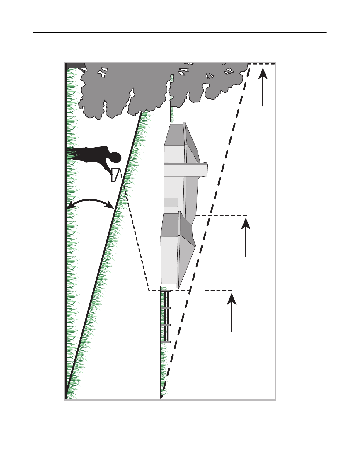
SECTION 3: SLOPE GAUGE
3IGHTANDHOLDTHISLEVELWITHAVERTICALTREE
&OLDALONGDOTTEDLINEREPRESENTSASLOPE
ORACORNEROFABUILDING
ORAFENCEPOST
8
Page 9
SECTION 4: TRACTOR SET-UP
Gas and Oil Fill-up
The gasoline tank is located under the hood and has a
capacity of 3 gallons. Do not overfill.
WARNING: Use extreme care when
handling gasoline. Gasoline is extremely
flammable and the vapors are explosive.
Never fuel machine indoors or while the
engine is hot or running. Extinguish
cigarettes, cigars, pipes, and other sources of
ignition before filling the fuel tank.
Service the engine with gasoline and oil as instructed in
the separate engine manufacturer’s Operator/Owner
Manual packed with your tractor. Read instructions
carefully.
Attaching The Steering Wheel
Tools Required
(1) 1/2" socket wrench
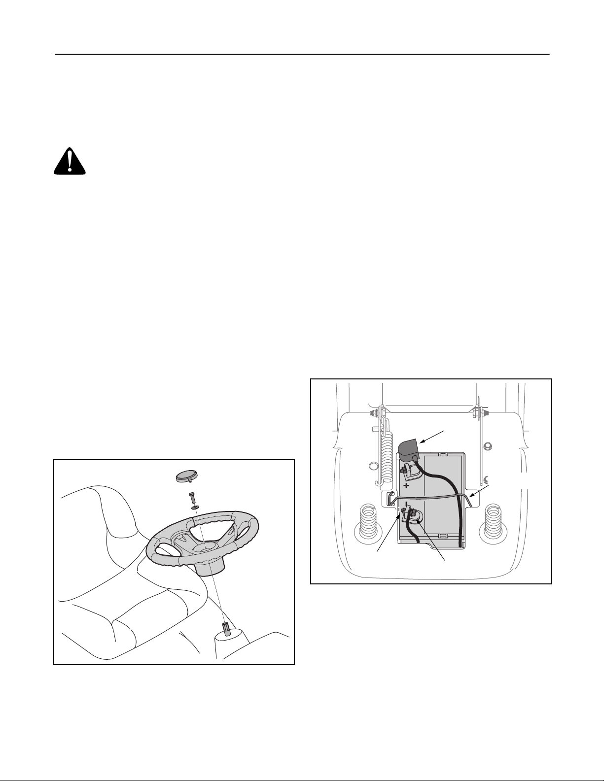
1. The hardware for attaching the steering wheel has
been packed within the steering wheel, beneath
steering wheel cap. Carefully pry off the steering
wheel cap and remove the hardware.
2. With the wheels of the tractor pointing straight
forward, place the steering wheel over the steering
shaft.
3. Place the washer (with the cupped side down) over
the steering shaft and secure with the hex bolt. See
Figure 1.
4. Place the steering wheel cap over the center of the
steering wheel and push downward until it “clicks”
into place.
Attaching the Battery Cables
Tools Required
(1) 7/16" wrench
NOTE: The positive battery terminal is marked Pos.
(+). The negative battery terminal is marked Neg. (–).
• The positive cable (heavy red wire) is secured to
the positive battery terminal (+) with a hex bolt and
hex nut at the factory. Make certain that the rubber
boot covers the terminal to help protect it from
corrosion.
• Remove the hex bolt and hex nut from the negative
cable.
• Remove the black plastic cover, if present, from the
negative battery terminal and attach the negative
cable (heavy black wire) to the negative battery
terminal (–) with the bolt and hex nut.
• Make certain the hold-down rod is in position over
the battery, securing it in place. See Figure 2.
Rubber
Boot
Figure 1
Hold Down Rod
Hex Nut
Hex Bolt
Figure 2
NOTE: If the battery is put into service after the date
shown on top of battery, charge the battery as
instructed on page 24 of this manual prior to operating
the tractor.
9
Page 10
Tire Pressure
Shipping Brace Removal
WARNING: Maximum tire pressure under
any circumstances is 30 psi. Equal tire
pressure should be maintained at all times.
The tires on your unit may be over-inflated for shipping
purposes. Reduce the tire pressure before operating
the tractor. Recommended operating tire pressure is
approximately 10 p.s.i for the rear tires & 14 p.s.i. for the
front tires. Check sidewall of tire for maximum p.s.i.
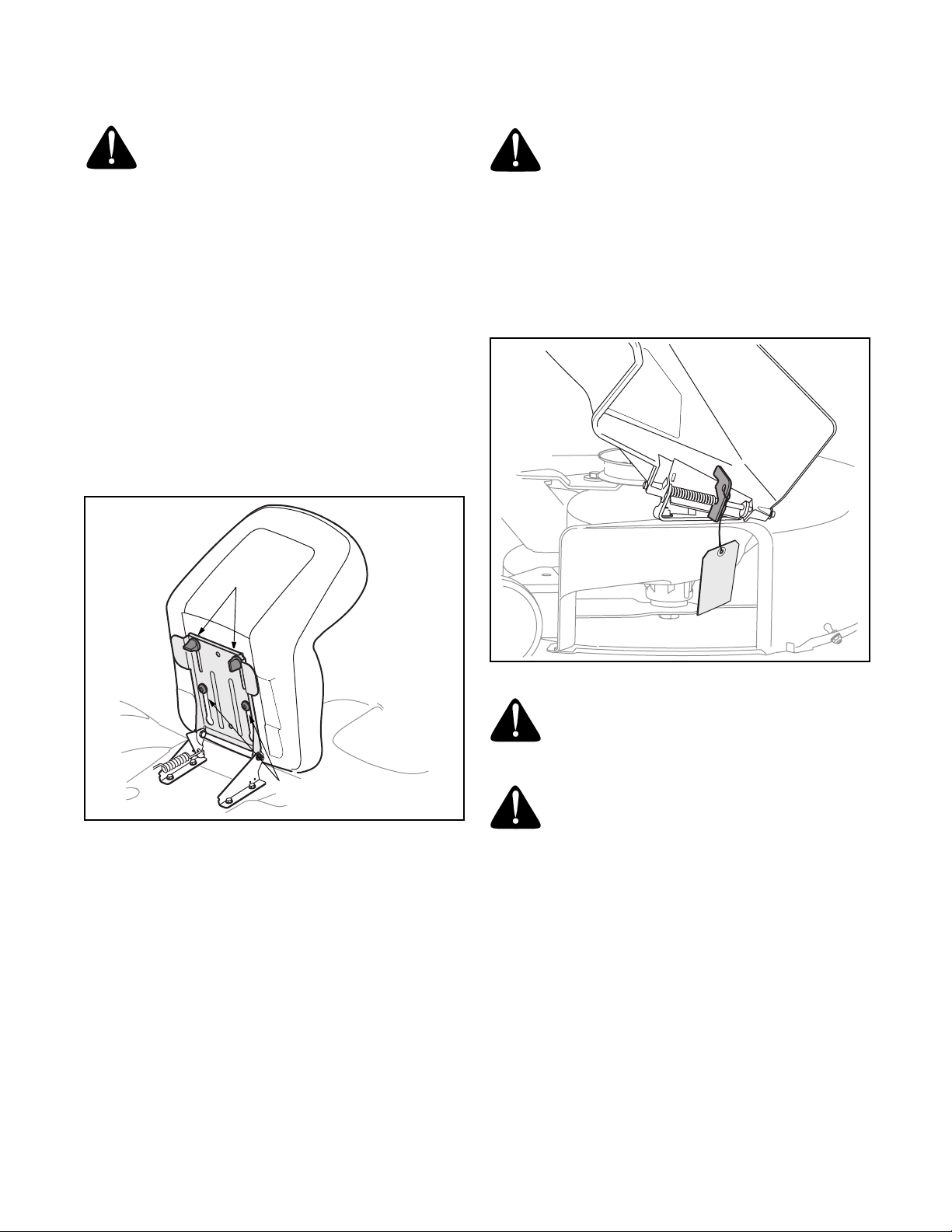
Attaching The Seat
1. Remove the two knobs from the bottom of seat.
2. Position the shoulder screws (found on the base of
the seat) inside the slot openings in the seat pivot
bracket.
3. Slide the seat slightly rearward in the seat pivot
bracket, lining up the rear slots in the pivot bracket
with the remaining two holes in the seat’s base.
4. Select desired position for the seat, and secure with
the two knobs removed earlier. See Figure 3.
Knobs
WARNING: Make sure the riding mower’s
engine is off, set the parking brake and
remove the ignition key before removing the
shipping brace
• Locate the shipping brace, if present, and warning
tag found on the right side of the cutting deck. See
Figure 4.
• While holding the discharge chute with your left
hand, remove the shipping brace with your right
hand by grasping it between your thumb and index
finger and rotating it clockwise.
.
Shoulder Screws
Figure 3
Figure 4
WARNING: The shipping brace, used for
packaging purposes only, must be removed
and discarded before operating your riding
mower.
WARNING: The mowing deck is capable of
throwing objects. Failure to operate the riding
mower without the discharge cover in the
proper operating position could result in
serious personal injury and/or property
damage.
10
Page 11
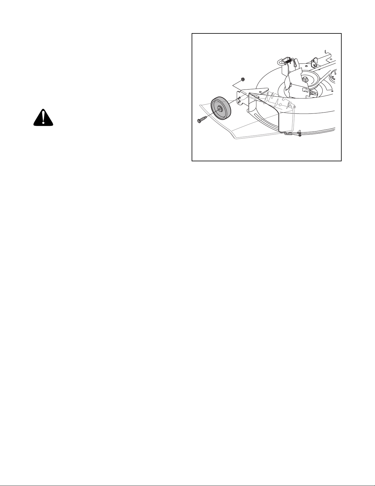
Setting the Gauge Wheels
Tools Required
(2) 9/16" wrenches
Select the height position of the cutting deck by placing
the deck lift lever in any of the six different cutting height
notches on the right fender.
Adjust the deck wheels so that they are between ¼-inch
and ½-inch above the ground as follows.
WARNING: Keep hands and feet away
from the discharge opening of the cutting
deck.
Place the tractor on a firm and level surface, preferably
pavement, refer to Figure 5, and proceed as follows:
• Place the tractor’s deck lift handle in the normally
desired mowing height setting, then check the
gauge wheels for contact or excessive clearance
with the surface below. There should be
approximately 1/2" clearance.
• If the wheels contact the surface adjust as follows:
a. Raise the deck lift handle to its highest
setting.
b. Remove the rear gauge wheels by removing
the lock nuts and shoulder screws which
secure them to the deck.
c. Place the deck lift handle in the desired
mowing height setting.
d. Insert the shoulder screw with the rear gauge
wheel into the index hole that leaves
approximately 1/2" between the bottom of the
wheel and the pavement. See Figure 5.
Figure 5
e. Note the position of the index hole used; then
install the other rear gauge wheel into the
corresponding index hole of the other gauge
wheel brackets.
• If the gauge wheels have excessive clearance with
the surface below, lower the wheels to the index
hole that provides the approximate 1/2" clearance
as described above.
Refer to Leveling the Deck on page 18 of this manual for
more detailed instructions regarding various deck
adjustments.
11
Page 12
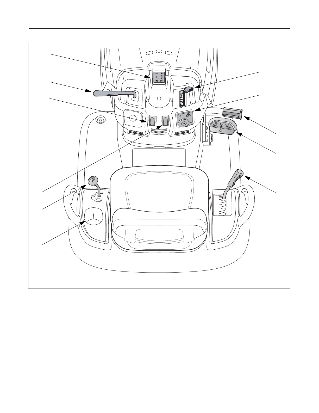
SECTION 5: KNOW YOUR LAWN TRACTOR
A
B
G
D
E
C
H
W
O
SL
I
J
K
F
NOTE: Steering Wheel not shown for clarity.
Figure 6
A Systems Indicator Monitor/Hour Meter G Throttle / Choke Control
B PTO (Blade Engage) Lever H Ignition Switch Module
C Parking Brake Lever I Brake Pedal
D Cruise Control Lever J Drive Pedal
E Shift Lever K Deck Lift Lever
F Cup Holder
NOTE: Any reference in this manual to the RIGHT or LEFT side of the tractor is observed from operator’s position.
12
Page 13
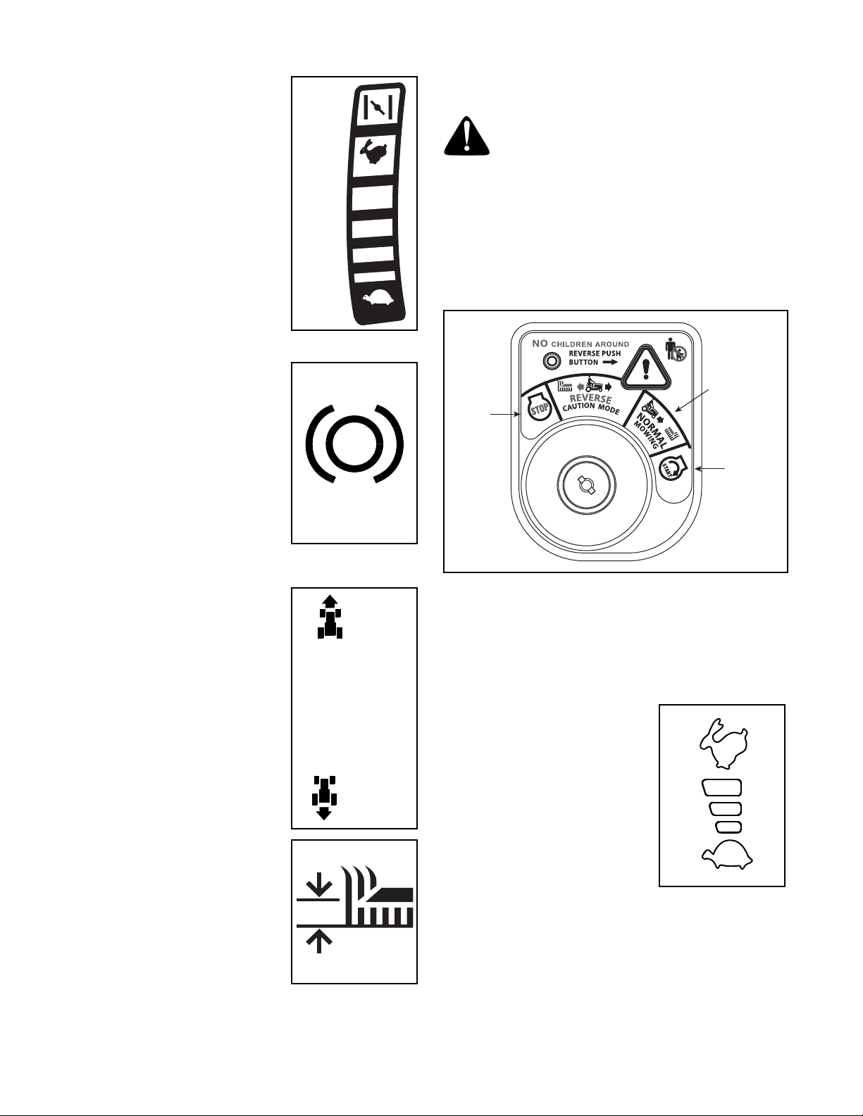
Throttle / Choke Control
The throttle/choke control is
located on the right side of the
tractor’s dash panel. This lever
controls the speed of the engine
and, when pushed all the way
forward, the choke control also.
When set in a given position, the
throttle will maintain a uniform
engine speed.
IMPORTANT:
tractor with the cutting deck
engaged, be certain that the
throttle/choke control is always
in the FAST (rabbit) position.
When operating the
Choke
Position
FAST
SLOW
Ignition Switch Module
WARNING: Never leave a running machine
unattended. Always disengage PTO, move
shift lever into neutral position, set parking
brake, stop engine and remove key to prevent
unintended starting.
To start the engine, insert the key into the ignition
switch and turn clockwise to the START position.
Release the key into the NORMAL MOWING MODE
position once the engine has fired.
To stop the engine, turn the ignition key
counterclockwise to the STOP position. See Figure 7.
Brake Pedal
The brake pedal is located on the
right front side of the tractor
above the drive pedal along the
running board. The brake pedal
can be used for sudden stops or
setting the parking brake.
NOTE: The brake pedal must
be fully depressed to activate the
safety interlock switch when
starting the tractor
.
Shift Lever
The shift lever is located on the
left side of the fender and has
three positions, FORWARD,
NEUTRAL and REVERSE. The
brake pedal must be depressed
and the tractor must not be in
motion when the moving shift
lever.
IMPORTANT:
lever. Doing so may result in
serious damage to the tractor’s
transmission.
Never force the shift
Deck Lift Lever
Found on your tractor’s right
fender, the deck lift lever is used
to change the height of the
cutting deck. To use, move the
lever to the left, then place in the
notch best suited for your
application.
F
N
R
Normal
Mowing Mode
Stop
Position
Start
Position
Figure 7
IMPORTANT:
Safety Interlock Switches on page 15 and Starting The Engine
on page 16 of this manual for detailed instructions
regarding the Ignition Switch Module and operating the
tractor in REVERSE CAUTION MODE.
Prior to operating the tractor, refer to both
Drive Pedal
The drive pedal is located below
the brake pedal on the right front
side of the tractor along the
running board. Depress the drive
pedal with your right foot when
the tractor shift lever is in either
FORWARD or REVERSE to
cause the tractor to move.
Ground speed is also controlled
with the drive pedal. The further
down the pedal is depressed, the faster the tractor will
travel. The pedal will return to its original position when
released.
13
Page 14
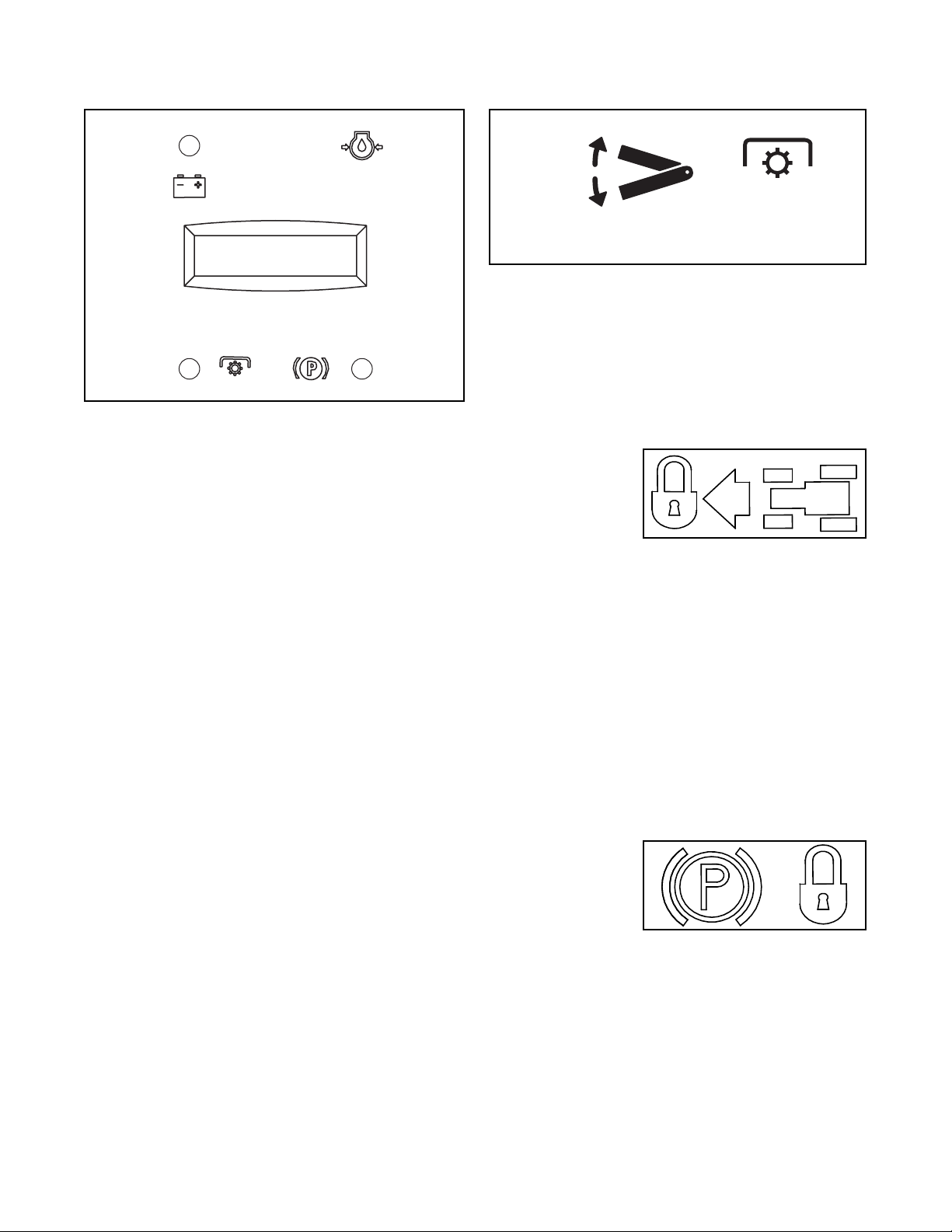
Systems Indicator Monitor / Hour Meter
PTO (Blade Engage) Lever
Battery
Oil
LCD
PTO
(Blade Engage)
42.0
Parking Brake
LCD
Located in the center of the tractor’s console, the
systems indicator monitor records, and displays on its
LCD, hours of tractor operation whenever the ignition
key is rotated out of the STOP position.
The Indicator Monitor will also remind the operator of
maintenance intervals for changing the engine oil. The
LCD will alternately flash the recorded hours, “CHG”
and “OIL” for five minutes, after every 50 hours of
recorded operation elapse. The maintenance interval
lasts for two hours (from 50-52, 100-102, 150-152,
etc.). The LCD will also flash as described above for
five minutes every time the tractor’s engine has been
started during this maintenance interval. Before the
interval expires, change the crankcase oil level as
instructed in the MAINTENANCE section of this manual.
Brake
If the Brake light illuminates when attempting to start
the tractor’s engine, depress the brake pedal.
PTO (Blade Engage)
If the PTO light illuminates when attempting to start the
tractor’s engine, move the PTO lever into the
disengaged (OFF) position.
Oil
It is normal for the Oil light to illuminate while the engine
is cranking during start-up, but if it illuminate’s during
operation, while the engine is running, stop the
tractor immediately and check the crankcase oil level
as instructed in the MAINTENANCE section of this manual.
Battery
It is normal for the Battery light to illuminate while the
engine is cranking during start-up, but if it illuminate’s
during operation, while the engine is running, the
battery is in need of a charge or the engine’s charging
system is not generating sufficient amperage. Refer to
the MAINTENANCE section of this manual for the proper
battery charging procedure or have the charging
system checked by a Kohler Engines dealer.
ON
OFF
PTO
PTO / BLADE ENGAGE
The PTO (Blade Engage) lever is located on the left
side of the dash, next to the steering wheel. Move the
PTO (Blade Engage) lever forward to engage the
power to the cutting deck or other (separately available)
attachments; move the PTO (Blade Engage) lever
rearward to disengage the power to the attachments.
NOTE: The PTO (Blade Engage) lever must be in the
disengaged (OFF) position when starting the engine.
Cruise Control Lever
The cruise control
lever is located on
the tractor dash
panel, below the steering wheel. Push the cruise
control lever downward while traveling forward at a
desired speed. While holding the lever down, release
pressure from the drive pedal.
This will engage the cruise control and allow the tractor
to remain at that speed without applying pressure to the
drive pedal. Depress the brake pedal or the drive pedal
to deactivate cruise control. Refer to page 17 for
detailed instructions regarding cruise control.
NOTE: Cruise control can NOT be engaged at the
tractor’s fastest ground speed. If the operator should
attempt to do so, the tractor will automatically
decelerate to the fastest optimal mowing ground speed.
Parking Brake Lever
To set the parking
brake, fully depress
the brake pedal and
push the parking brake lever down. Hold the lever down
while taking your foot off the brake pedal. Both the
parking lever and the brake pedal will then stay
depressed. To release the parking brake, depress the
brake pedal slightly. The parking brake lever will then
return to its original position.
IMPORTANT:
leaving the tractor unattended.
Always set the parking brake when
14
Page 15
SECTION 6: OPERATING YOUR LAWN TRACTOR
Safety Interlock System
This tractor is equipped with a safety interlock system
for the protection of the operator. Before each use,
check the safety interlock system for proper operation.
If the interlock system should ever malfunction, do not
operate the tractor. Contact an authorized Toro service
dealer.
• The safety interlock system prevents the engine
from cranking or starting unless the parking brake is
engaged, and the PTO (Blade Engage) lever is in
the disengaged (OFF) position. To check for proper
operation, move the PTO (Blade Engage) lever into
the engaged (ON) position and release the parking
brake. Attempts to start the tractor’s engine should
fail.
• The engine will automatically shut off if the operator
leaves the seat before engaging the parking brake.
To check for proper operation, start the tractor’s
engine, release the parking brake and momentarily
raise yourself from the seat. The engine should
stall.
• The engine will automatically shut off if the operator
leaves the tractor’s seat with the PTO (Blade
Engage) lever in the engaged (ON) position,
regardless of whether the parking brake is
engaged. To check for proper operation, start the
tractor’s engine, move the PTO (Blade Engage)
lever in the engaged (ON) position and momentarily
raise yourself from the seat. The engine should
stall.
• With the ignition key in the NORMAL MOWING
position, the engine will automatically shut off if the
PTO (Blade Engage) lever is moved into the
engaged (ON) position with the shift lever in
Reverse. To check for proper operation, start the
tractor’s engine with the ignition key in the
NORMAL MOWING position, engage the parking
brake, move the PTO (Blade Engage) lever in the
engaged (ON) position and place the shift lever into
REVERSE. The engine should stall.
WARNING: Do not operate the tractor if the
interlock system is malfunctioning. This
system was designed for your safety and
protection.
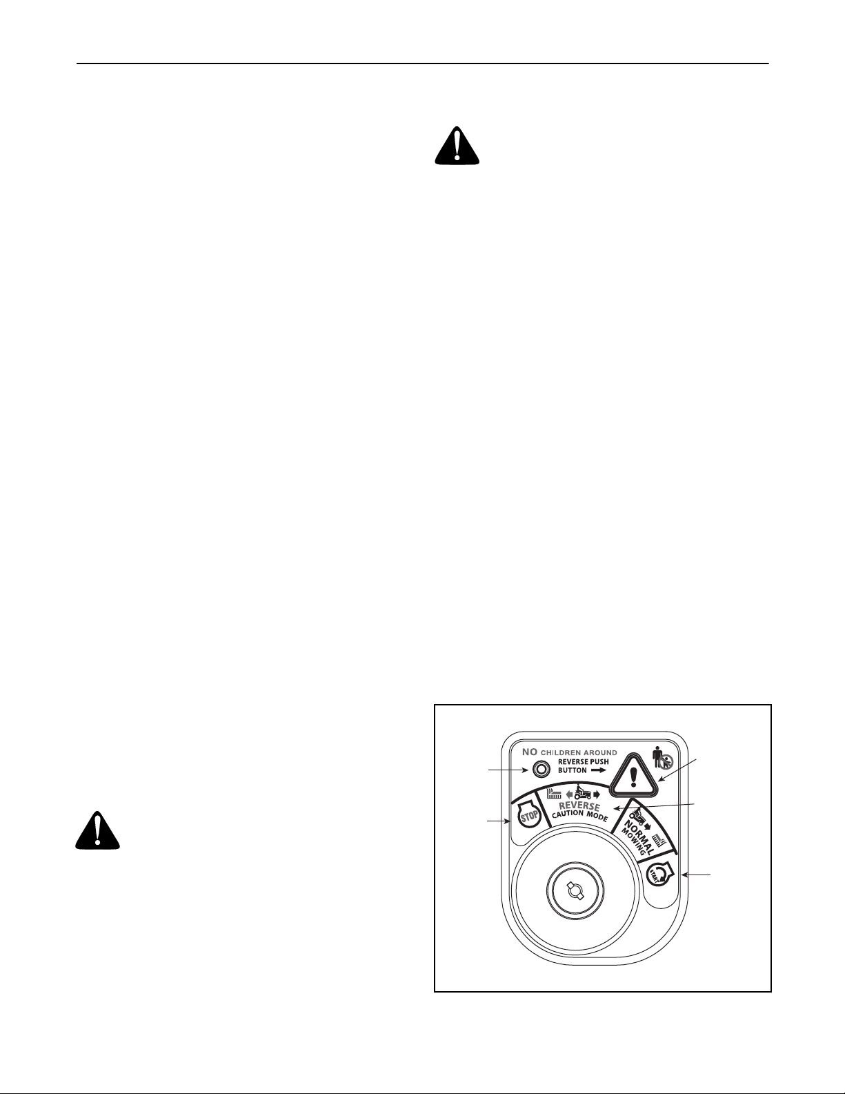
Reverse Caution Mode
The REVERSE CAUTION MODE position of the key
switch module allows the tractor to be operated in
reverse with the blades (PTO) engaged.
IMPORTANT: Mowing in reverse is not recommended.
WARNING: Use extreme caution while
operating the tractor in the REVERSE
CAUTION MODE. Always look down and
behind before and while backing. Do not
operate the tractor when children or others
are around. Stop the tractor immediately if
someone enters the area.
To use the REVERSE CAUTION MODE:
IMPORTANT:
tractor seat.
1. Start the engine as previously instructed in this
Operator’s Manual.
2. Turn the key from the NORMAL MOWING
(Green) position to the REVERSE CAUTION
MODE (Yellow) position of the key switch module.
See Figure 8.
3. Depress the REVERSE PUSH BUTTON (Orange,
Triangular Button) at the top, right corner of the key
switch module. The red indicator light at the top, left
corner of the key switch module will be ON while
activated. See Figure 8.
4. Once activated (indicator light ON), the tractor can
be driven in reverse with the cutting blades (PTO)
engaged.
5. Always look down and behind before and while
backing to make sure no children are around.
6. After resuming forward motion, return the key to the
NORMAL MOWING position.
IMPORTANT:
remain activated until:
Indicator
Light
Stop
Position
The operator MUST be seated in the
The REVERSE CAUTION MODE will
a. The key is placed in either the NORMAL
MOWING position or STOP position.
b. The operator leaves the seat.
Reverse
Push Button
Reverse
Caution Mode
Position
Start
Position
15
Figure 8
Page 16

Starting the Engine
Driving The Tractor
WARNING: Do not operate the tractor if the
interlock system is malfunctioning. This
system was designed for your safety and
protection.
NOTE: Refer to the TRACTOR SET-UP on page 9 of this
manual for Gasoline and Oil fill-up instructions.
• Insert the tractor key into the ignition switch
module.
• Place the PTO (Blade Engage) lever in the
disengaged (OFF) position.
• Engage the tractor’s parking brake.
• Activate the choke control.
• Turn the ignition key clockwise to the START
position. After the engine starts, release the key. It
will return to the NORMAL MOWING position.
IMPORTANT:
position for longer than ten seconds at a time. Doing so
may cause damage to your engine’s electric starter.
• After the engine starts, deactivate the choke
control.
Do NOT hold the key in the START
NOTE: Do NOT leave the choke control on while
operating the tractor. Doing so will result in a "rich" fuel
mixture and cause the engine to run poorly.
WARNING: Avoid sudden starts, ex-
cessive speed and sudden stops.
WARNING: Do not leave the seat of the
tractor without first placing the PTO (Blade
Engage) lever in the disengaged (OFF)
position, depressing the brake pedal and
engaging the parking brake. If leaving the
tractor unattended, also turn the ignition key
off and remove the key.
• Depress the brake pedal to release the parking
brake and let the pedal up.
• Move the throttle/choke control into the FAST
(rabbit) position.
IMPORTANT:
direction of travel when the tractor is in motion. Always
use the brake pedal to bring the tractor to a complete
stop before shifting.
• To move forward, place the shift lever in the
FORWARD position, then slowly depress the drive
pedal until the desired speed is achieved.
• To move in reverse, place the shift lever in the
REVERSE position, check that the area behind is
clear then slowly depress the drive pedal.
Do NOT use the shift lever to change the
Stopping the Engine
WARNING: If you strike a foreign object,
stop the engine, disconnect the spark plug
wire(s) and ground against the engine.
Thoroughly inspect the machine for any
damage. Repair the damage before restarting
and operating
• If the blades are engaged, place the PTO/Blade
Engage lever in the disengaged (OFF) position.
• Position the throttle/choke control between halfthrottle and the FAST (rabbit) position
• Turn the ignition key counterclockwise to the STOP
position.
• Remove the key from the ignition switch to prevent
unintended starting.
Using the Deck Lift Lever
To raise the cutting deck, move the deck lift lever to the
left, then place it in the notch best suited for your
application. Refer to Setting The Cutting Height earlier in
this section.
Driving On Slopes
Refer to the SLOPE GAUGE on page 8 to help determine
slopes where you may operate the tractor safely.
WARNING: Do not mow on inclines with a
slope in excess of 15 degrees (a rise of
approximately 2-1/2 feet every 10 feet). The
tractor could overturn and cause serious
injury.
• Mow up and down slopes, NEVER across.
• Exercise extreme caution when changing direction
on slopes.
• Watch for holes, ruts, bumps, rocks, or other
hidden objects. Uneven terrain could overturn the
machine. Tall grass can hide obstacles.
• Avoid turns when driving on a slope. If a turn must
be made, turn down the slope. Turning up a slope
greatly increases the chance of a roll over.
• Avoid stopping when driving up a slope. If it is
necessary to stop while driving up a slope, start up
smoothly and carefully to reduce the possibility of
flipping the tractor over backward.
16
Page 17

Setting The Cruise Control
NOTE: The cruise control feature should only be
utilized while traveling in the forward direction.
• Slowly depress the drive pedal until the desired
speed is achieved.
• Lightly depress the cruise control lever.
• While continuing to hold the cruise lever down, lift
your foot from the drive pedal (you should feel the
cruise latch engage).
• Once engaged, the cruise control lever and the
drive pedal will lock in the “down” position, and the
tractor will maintain the same forward speed.
NOTE: Cruise control can not be set at the tractor’s
fastest ground speed. If the operator should attempt to
do so, the tractor will automatically decelerate to the
fastest optimal mowing ground speed.
Disengage the cruise control using one of the following
methods:
• Depress the brake pedal to disengage the cruise
control and stop the tractor.
• Lightly depress the drive pedal.
To change to the reverse direction when operating with
cruise control, depress the brake pedal to disengage
the cruise control and bring the tractor to a complete
stop. Place the shift lever in the REVERSE position and
depress the drive pedal.
Engaging the Parking Brake
To engage the parking brake:
• Fully depress the brake pedal and hold it while
gently pushing the parking brake lever downward.
• Hold the parking brake lever down while removing
your foot from the brake pedal.
• Once engaged, the parking brake lever and the
brake pedal will lock in the “down” position.
To disengage the parking brake:
• Slightly depress the brake pedal.
NOTE: The parking brake must be engaged if the
operator leaves the seat with the engine running or the
engine will automatically shut off.
Engaging the Blades
Engaging the PTO (Blade Engage) transfers power to
the cutting deck or other (separately available)
attachments. To engage the blades, proceed as
follows:
• Move the throttle/choke control to the FAST (rabbit)
position.
• Grasp the PTO (Blade Engage) lever and pivot it all
the way forward into the engaged (ON) position.
• Keep the throttle/choke control in the FAST (rabbit)
position for the most efficient use of the cutting
deck or other (separately available) attachments
IMPORTANT:
PTO is engaged with the shift lever in position for
reverse travel and the ignition key in the NORMAL
MOWING position. Refer to Safety Interlock System on
page 15.
The engine will automatically shut off if the
Mowing
WARNING: To help avoid blade contact or
a thrown object injury, keep bystanders,
helpers, children and pets at least 75 feet
from the machine while it is in operation. Stop
machine if anyone enters the area.
This tractor is equipped with one of Toro’s quality
cutting decks. The following information will be helpful
when using the cutting deck with your tractor.
WARNING: Plan your mowing pattern to
avoid discharge of materials toward roads,
sidewalks, bystanders and the like. Also,
avoid discharging material against a wall or
obstruction which may cause discharged
material to ricochet back toward the operator.
• Do not mow at high ground speed, especially if a
mulch kit or grass collector is installed.
• For best results it is recommended that the first two
laps be cut with the discharge thrown towards the
center. After the first two laps, reverse the direction
to throw the discharge to the outside for the
balance of cutting. This will give a better
appearance to the lawn.
• Do not cut the grass too short. Short grass invites
weed growth and yellows quickly in dry weather.
• Mowing should always be done with the engine at
full throttle.
• Under heavier conditions it may be necessary to go
back over the cut area a second time to get a clean
cut.
• Do NOT attempt to mow heavy brush and weeds
and extremely tall grass. Your tractor is designed to
mow lawns, NOT clear brush.
• Keep the blades sharp and replace the blades
when worn. Refer to Cutting Blades on page 23 of this
manual for proper blade sharpening instructions.
17
Page 18
SECTION 7: MAKING ADJUSTMENTS
WARNING: Never attempt to make any
adjustments while the engine is running,
Seat Adjustment
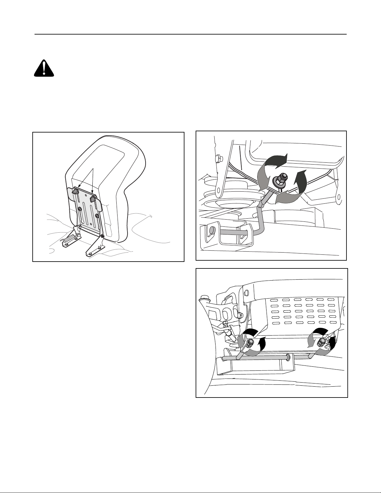
To adjust the position of the seat, loosen the two knobs
on the bottom of the seat. See Figure 9. Slide the seat
forward or rearward as desired. Retighten the two
knobs.
Knobs
• Determine the approximate distance necessary for
proper adjustment and proceed, if necessary, to the
next step.
• From the front of the tractor, loosen the outermost
hex lock nut on the end of the deck hanger rod. See
Figure 10 or Figure 11.
• Tighten the inner hex nut front against the front
hanger bracket to raise the front of the deck; loosen
the hex nut to lower the front of the deck. See
Figure 10 or Figure 11.
LX 420
Figure 9
Leveling the Deck
NOTE: Check the tractor’s tire pressure before
performing any deck leveling adjustments. Refer to
Tires on page 23 for information regarding tire pressure.
Front To Rear
The front of the cutting deck is supported by a stabilizer
bar that can adjusted to level the deck from front to rear.
The front of the deck should be between 1/4-inch and
3/8-inch lower than the rear of the deck. Adjust if
necessary as follows:
• With the tractor parked on a firm, level surface,
place the deck lift lever in the top notch (highest
position) and rotate the blade nearest the discharge
chute so that it is parallel with the tractor.
• Measure the distance from the front of the blade tip
to the ground and the rear of the blade tip to the
ground.
• The first measurement taken should be between
1/4" and 3/8" less than the second measurement.
Figure 10
LX 460
Figure 11
• Retighten the two lock nuts against the inner hex
nuts when proper adjustment is achieved.
18
Page 19
Side to Side
If the cutting deck appears to be mowing unevenly, a
side to side adjustment can be performed. Adjust if
necessary as follows:
• With the tractor parked on a firm, level surface,
place the deck lift lever in the top notch (highest
position) and rotate both blades so that they are
perpendicular with the tractor.
• Measure the distance from the outside of the left
blade tip to the ground and the distance from the
outside of the right blade tip to the ground. Both
measurements taken should be equal. If they’re
not, proceed to the next step.
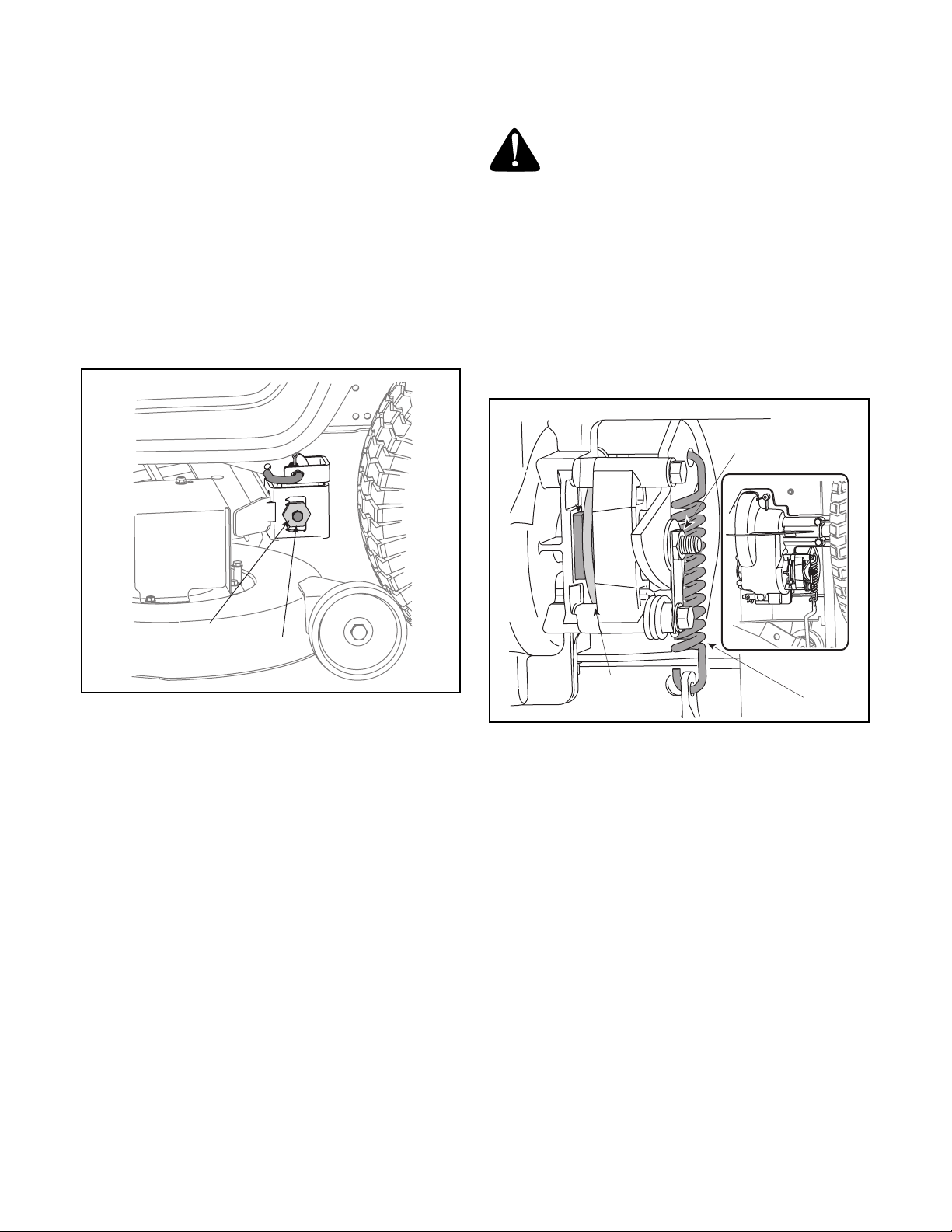
• Loosen, but do NOT remove, the hex bolt on the left
deck hanger bracket. See Figure 12.
Parking Brake Adjustment
WARNING: Never attempt to adjust the
brakes while the engine is running. Always
disengage PTO, move shift lever into neutral
position, stop engine and remove key to
prevent unintended starting.
If the tractor does not come to a complete stop when
the brake pedal is completely depressed, or if the
tractor’s rear wheels can roll with the parking brake
applied, the brake is in need of adjustment. The brake
disc can be found on the right side of the transmission
in the rear of the tractor. Adjust if necessary as follows:
• Looking at the transmission from the right side of
the tractor, locate the compression spring and
brake disc. See Figure 13.
Brake Puck
Hex Nut
Adjustment Gear
Hex Bolt
Figure 12
• Balance the deck by using a wrench to turn the
adjustment gear (See Figure 12) up or down.
• The deck is properly balanced when both blade tip
measurements taken earlier are equal.
• Retighten the hex bolt on the left deck hanger
bracket when proper adjustment is achieved.
Brake Disc
Spring
Figure 13
• Loosen, but do NOT remove, the hex nut found on
the right side of the brake assembly. See Figure 13.
• Insert a feeler gauge (set at .011”) between the
brake disk and the brake puck.
NOTE: If a feeler gauge is unavailable, a typical
business card is approximately .011” thick.
• Retighten the hex nut loosened earlier, leaving a
.011” gap between the brake disc and the brake
puck.
19
Page 20
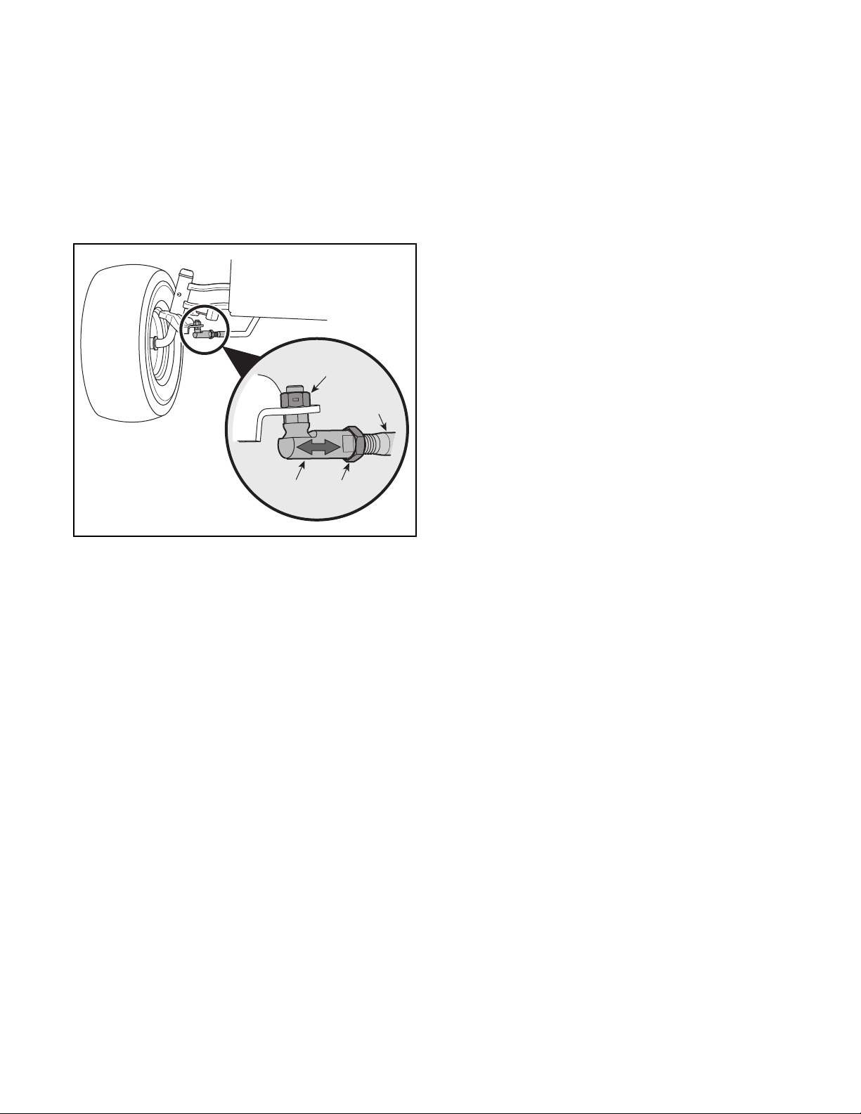
Steering Adjustment
If the tractor turns tighter in one direction than the other,
or if the ball joints are being replaced due to damage or
wear, the steering drag links may need to be adjusted.
Adjust the drag links so that equal lengths are threaded
into the ball joint on the left side and the ball joint on the
right side:
• Loosen the jam nut found on the drag link at the
rear of the ball joint. See Figure 14.
Hex Nut
Drag Link
Ball
Joint
Jam
Nut
• Remove the hex nut on the top of ball joint. See
Figure 14.
• Thread the ball joint toward the jam nut to shorten
the drag link. Thread the ball joint away from the
jam nut to lengthen the drag link.
• Replace hex nut and lock washer and retighten the
jam nut after proper adjustment is achieved.
NOTE: Threading the ball joints too far onto the drag
links will cause the front tires to "toe-in" too far. Proper
toe-in is between 1/16" and 5/16".
Front tire toe-in can be measured as follows:
• Place the steering wheel in position for straight
ahead travel.
• In front of the axle, measure the distance
horizontally from the inside of the left rim to the
inside of the right rim. Note the distance.
• Behind the axle, measure the distance horizontally
from the inside of the left rim to the inside of the
right rim. Note the distance.
• The measurement taken in front of the axle should
be between 1/16" and 5/16" less than the
measurement taken behind the axle.
• Adjust if necessary.
Figure 14
20
Page 21
SECTION 8: MAINTAINING YOUR LAWN TRACTOR
NOTE: Refer to Maintenance Chart on page 28 for a
reference of recommended maintenance intervals.
WARNING: Before performing any
maintenance or repairs, disengage PTO, set
parking brake, stop engine and remove key to
prevent unintended starting.
Engine
Maintenance, repair, or replacement of the emission
control devices and systems, which are being done at
the customer’s expense, may be performed by any
engine repair establishment or individual. Warranty
repairs must be performed by an authorized Toro
Dealer.
Refer to the Kohler Engines Owner’s Manual for
engine maintenance instructions.
Check engine oil level before each use as instructed in
the Kohler Engines Owner’s Manual packed with your
unit. Follow the instructions carefully.
Changing Engine Oil
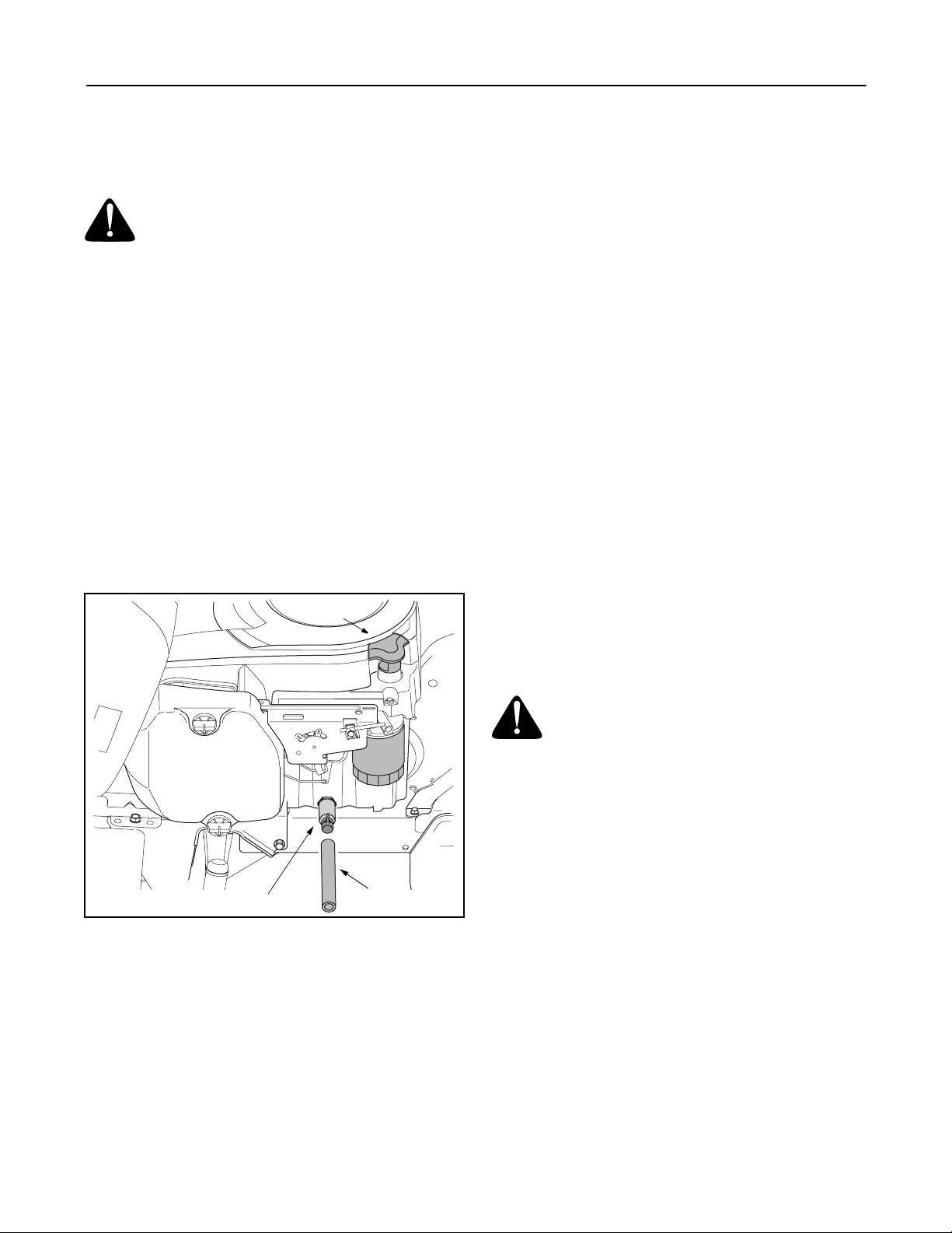
• Carefully full upward on the oil fill cap and remove
dipstick from the oil fill tube. See Figure 15.
Oil Fill Cap
• Push the oil drain hose (packed with this manual)
onto the oil drain port. Route the opposite end of
the hose into an appropriate oil collection container
with a capacity of no less than 64 oz.
• Push the oil drain valve in slightly, then rotate
counterclockwise and pull outward to begin
draining oil. See Figure 15.
• Service the oil filter as instructed in the separate
Kohler Engines Owner’s Manual packed with your
unit.
Perform the above steps in the opposite order after oil
has finished draining.
• Refill the engine with new motor oil.
IMPORTANT:
Manual packed with your unit for information regarding
the quantity and proper weight of motor oil.
Refer to the Kohler Engines Owner’s
Air Cleaner
Service the pre-cleaner, if so equipped, and cartridge/
air cleaner element as instructed in the Kohler Engines
Owner’s Manual packed with your unit.
Spark Plug(s)
The spark plug(s) should be cleaned and the gap reset
once a season. Spark plug replacement is
recommended at the start of each mowing season.
Refer to the Kohler Engines Owner’s Manual for correct
plug type and gap specifications.
Fuel Filter
Drain Port
Figure 15
• Pop open the protective cap on the end of the oil
drain valve to expose the drain port. See Figure 15.
Oil Drain Hose
WARNING: Do not replace the fuel filter
when engine is hot.
The engine is equipped with an inline fuel filter located
on the right side of the engine.
Visually inspect the filter periodically for a build-up of
residue inside the filter body, and for a dirty element
which can be indicated by discoloration. Replace the
filter when dirty, or after every 100 hours of operation.
Cleaning the Engine And Deck
Any fuel or oil spilled on the machine should be wiped
off promptly.
Do NOT allow debris to accumulate around the cooling
fins of the engine or on any other part of the machine,
especially the belts and pulleys.
21
Page 22
Lubrication
WARNING: Before lubricating, repairing, or
inspecting, always disengage PTO, set
parking brake, stop engine and remove key to
prevent unintended starting.
Engine
Refer to Engine on page 21 for instruction regarding all
engine-related lubrication.
Front Wheels
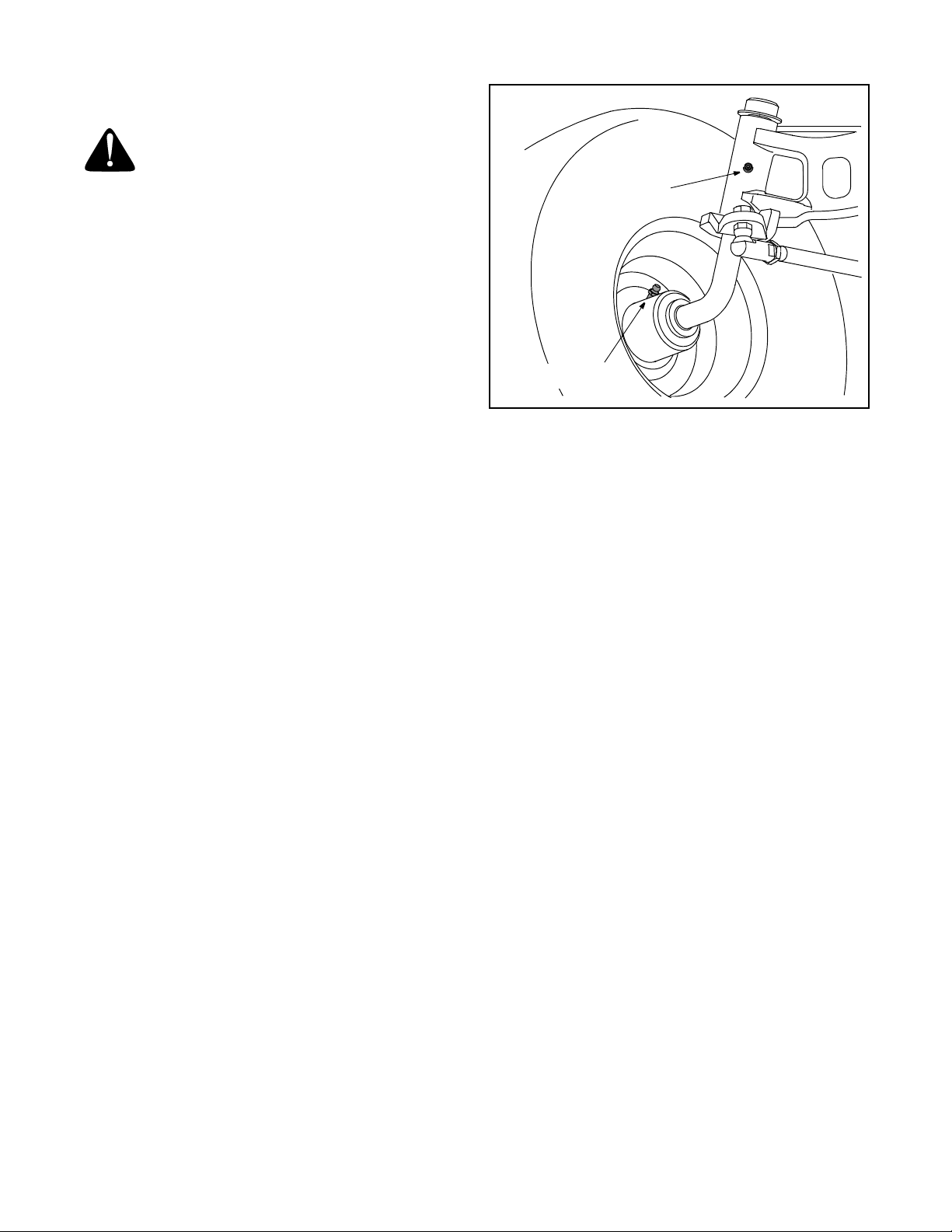
Each of the front wheel axles and rims is equipped with
a grease fitting. See Figure 16. Lubricate with a grease
gun after every 25 hours of tractor operation.
Pivot Points & Linkage
Lubricate all the pivot points on the drive system,
parking brake and lift linkage at least once a season
with light oil.
Axle Grease Fitting
Rim Grease Fitting
Figure 16
22
Page 23
SECTION 9: SERVICE
Tires
WARNING: Never exceed the maximum
inflation pressure shown on the sidewall of the
tire.
The recommended operating tire pressure is
approximately 10 psi for the rear tires and 14 psi for the
front tires. Do not overinflate. Uneven tire pressure
could cause the cutting deck to mow unevenly.
Fuse
A fuse is installed in your tractor’s wiring harness to
protect the tractor’s electrical system from damage
caused by excessive amperage.
If the electrical system does not function, or your
tractor’s engine will not crank, first check to be certain
that the fuse has not blown.
It can be found under the hood mounted behind the top
of the dash panel on the support bar.
IMPORTANT:
amperage capacity for replacement.
Always use a fuse with the same
WARNING: Before servicing, repairing, or
inspecting, always disengage PTO, set
parking brake, stop engine and remove key to
prevent unintended starting.
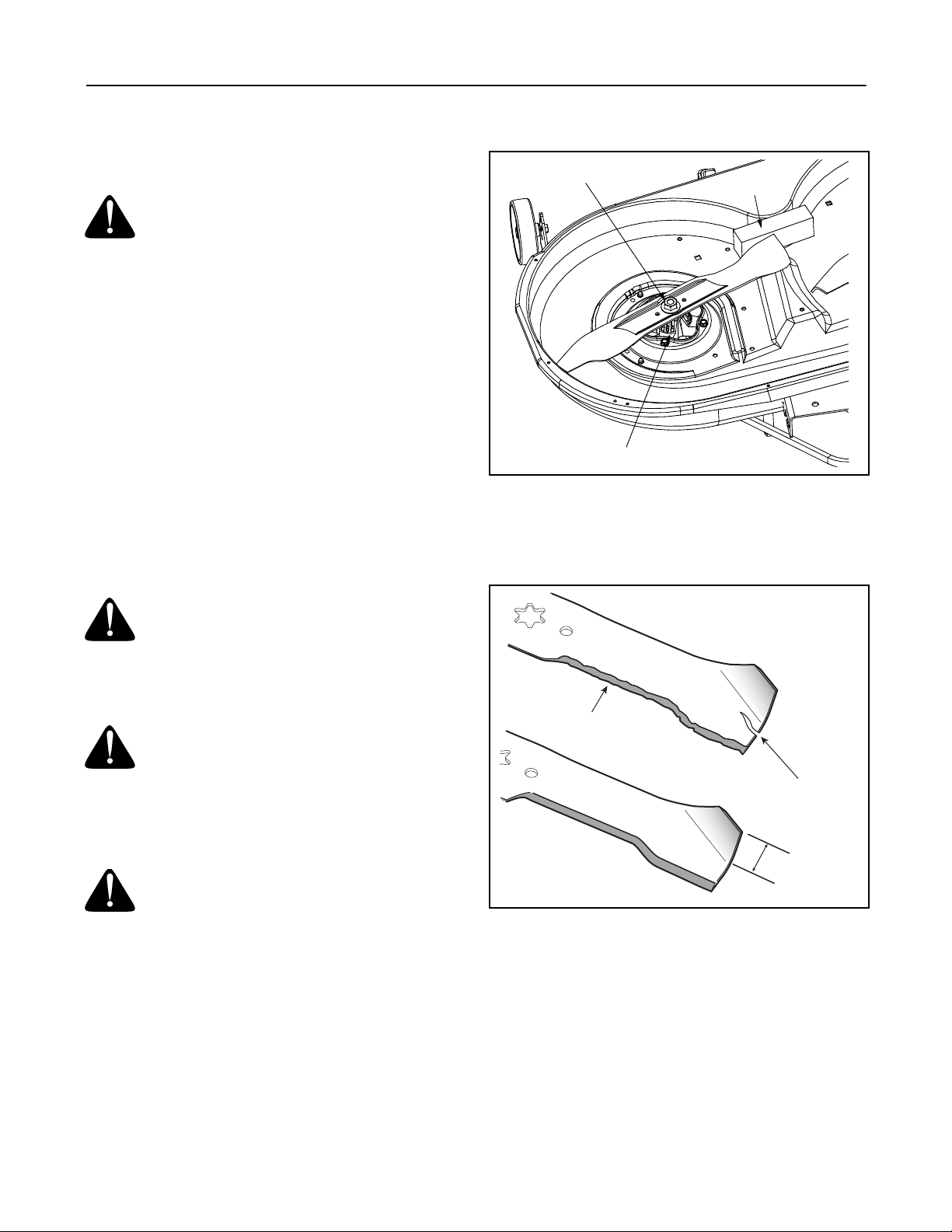
Hex Flange Nut
Wood Block
Spindle Assembly
Figure 17
• To properly sharpen the cutting blades, remove
equal amounts of metal from both ends of the
blades along the cutting edges, parallel to the
trailing edge, at a 25° to 30° angle.
Cutting Blades
WARNING: Be sure to shut the engine off,
remove ignition key, disconnect the spark plug
wire(s) and ground against the engine to
prevent unintended starting before removing
the cutting blade(s) for sharpening or
replacement. Protect your hands by using
heavy gloves when grasping the blade.
WARNING: Periodically inspect the blade
adapter and/or spindle for cracks or damage,
especially if you strike a foreign object.
Replace immediately if damaged
The blades may be removed as follows.
• Remove the deck from beneath the tractor, (refer to
Cutting Deck Removal on page 24) then gently flip the
deck over to expose its underside.
• Place a block of wood between the center deck
housing baffle and the cutting blade to act as a
stabilizer. See Figure 17.
• Use a 1-1/8" wrench to remove the hex flange nut
that secures the blade to the spindle assembly. See
Figure 17.
.
Damaged Blade Edge
Seperation
1-5/8 inch
Figure 18
IMPORTANT:
been sharpened, or if any metal separation is present,
replace the blades with new ones.
It is important that each cutting blade edge be ground
equally to maintain proper blade balance. A poorly
balanced blade will cause excessive vibration and may
cause damage to the tractor and result in personal
injury. The blade can be tested by balancing it on a
round shaft screwdriver. Grind metal from the heavy
side until it balances evenly.
If the cutting edge of the blade has already
23
Page 24
IMPORTANT:
install the blade with the side of the blade marked
‘‘Bottom’’ (or with a part number stamped in it) facing
the ground when the mower is in the operating position.
IMPORTANT:
spindle hex flange nut to between 70 lbs-ft. and 90 lbsft.
When replacing the blade, be sure to
Use a torque wrench to tighten the blade
Battery
California Proposition 65 Warning: Battery
posts, terminals, and related accessories
contain lead and lead compounds, chemicals
known to the State of California to cause
cancer and reproductive harm. Wash hands
after handling.
The battery is sealed and is maintenance-free. Acid
levels cannot be checked and fluid can not be added.
• Always keep the battery cables and terminals clean
and free of corrosive build-up.
• After cleaning the battery and terminals, apply a
light coat of petroleum jelly or grease to both
terminals
• Always keep the rubber boot positioned over the
positive terminal to prevent shorting.
IMPORTANT:
NEGATIVE (Black) wire from it’s terminal first, followed
by the POSITIVE (Red) wire. When re-installing the
battery, always connect the POSITIVE (Red) wire its
terminal first, followed by the NEGATIVE (Black) wire.
Be certain that the wires are connected to the correct
terminals; reversing them could change the polarity and
cause damage to your engine’s alternating system.
If removing the battery, disconnect the
• Set the tractor’s parking brake before removing the
jumper cables, in reverse order of connection.
• Allow the tractor’s engine to run for 15 minutes
before shutting it off to allow the alternating system
time to charge the discharged battery.
Charging
If the unit has not been put into use for an extended
period of time, charge the battery with an automotivetype 12-volt charger for a minimum of one hour at six
amps.
WARNING: Batteries give off an explosive
gas while charging. Charge battery in a well
ventilated area and keep away from an open
flame or pilot light as on a water heater, space
heater, furnace, clothes dryer or other gas
appliances.
Cutting Deck Removal
To remove the cutting deck, proceed as follows:
• Place the PTO/Blade Engage lever in the
disengaged (OFF) position and engage the parking
brake.
• Lower the deck by moving the deck lift lever into the
bottom notch on the right fender.
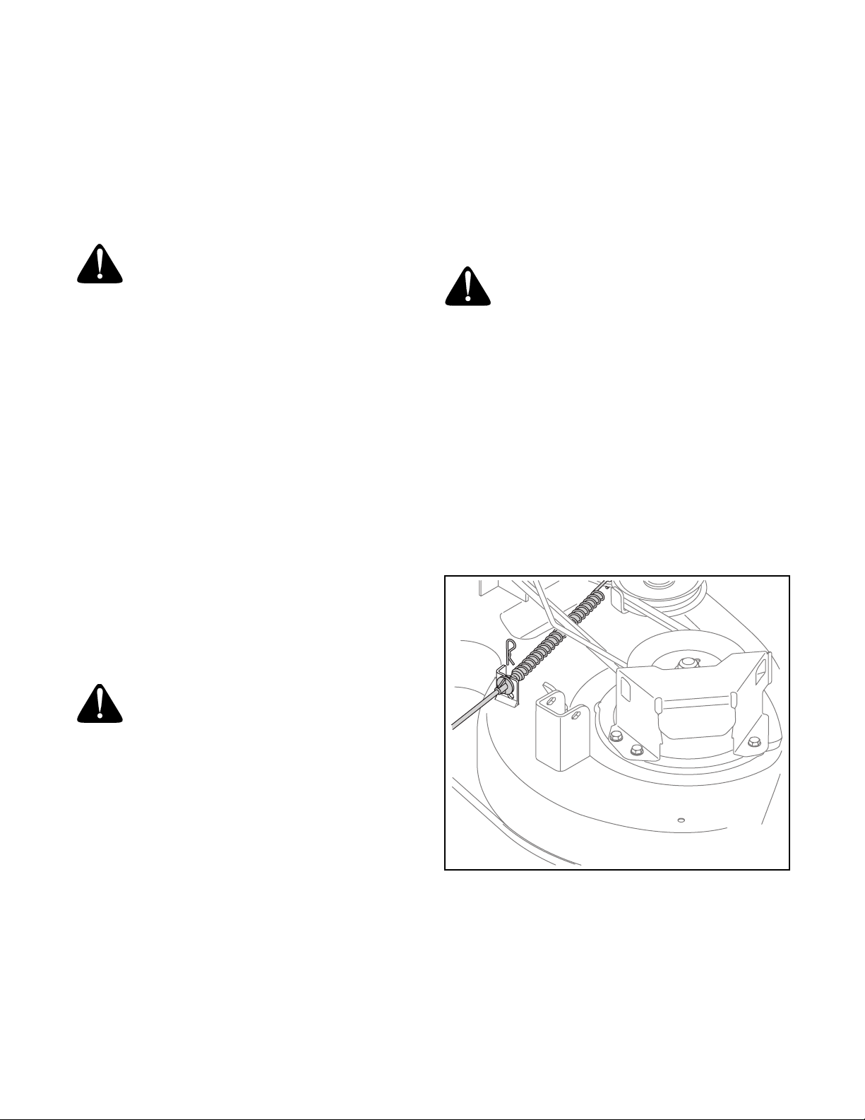
• Remove the hairpin clip that secures the PTO cable
to the rear of the cutting deck. See Figure 19.
Remove the PTO cable and accompanying spring
from the cutting deck.
Jump Starting
WARNING: Never jump start a damaged or
frozen battery. Be certain the vehicles do not
touch, and ignitions are off. Do not allow cable
clamps to touch.
• Connect positive (+) cable to positive post (+) of
your tractor’s discharged battery.
• Connect the other end of the cable to the (positive
+) post of the jumper battery.
• Connect the second cable (negative –) to the other
post of the jumper battery.
• Make the final connection on the engine block of
the stalled tractor, away from the battery. Attach to
a unpainted part to assure a good connection.
IMPORTANT:
vehicle (i.e. car, truck), do NOT start the vehicle’s
engine when jump starting your tractor.
• Start the tractor (as instructed on page 16).
If the jumper battery is installed on a
Figure 19
• Remove the deck belt from around the tractor’s
engine pulley.
• Looking at the cutting deck from the left side of the
tractor, locate the deck support pin on the rear left
side of the deck.
24
Page 25
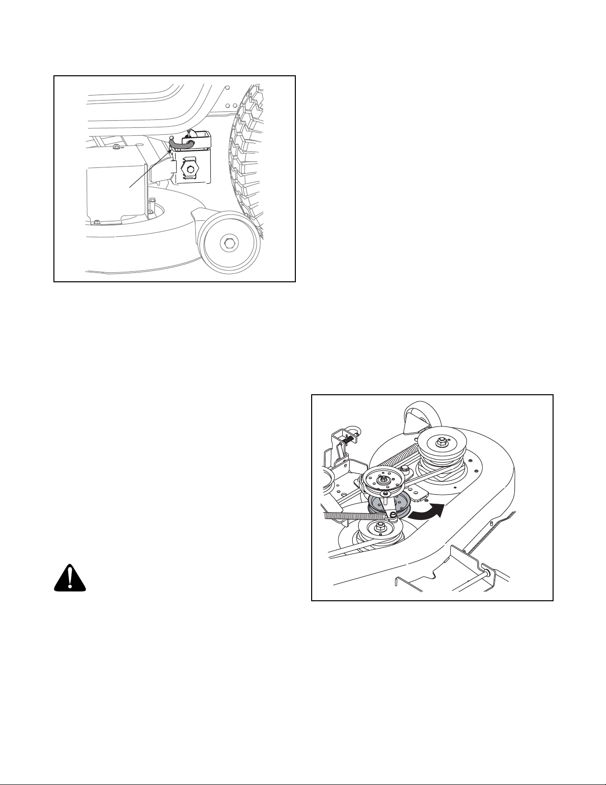
• Pull the deck support pin outward to release the
deck from the deck lift arm. See Figure 20.
Support Pin
Figure 20
• Repeat the above steps on the tractor’s right side.
• Move the deck lift lever into the top notch to raise
the deck lift arms up and out of the way.
• Gently slide the cutting deck toward the front of the
tractor allowing the hooks on the deck to release
themselves from the deck stabilizer rod.
• Gently slide the cutting deck (from the right side)
out from underneath the tractor.
To change or replace the deck belt on your tractor,
proceed as follows:
• Remove the belt keeper rod(s) from around the
engine pulley.
• Remove the cutting deck as instructed earlier in this
section.
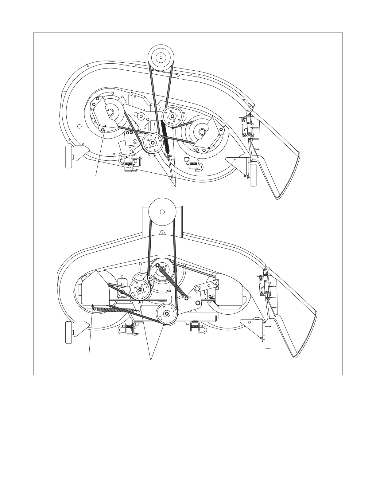
• Remove the belt covers by removing the screws
that fasten them to the deck. Refer to the figure on
the following page.
• Loosen, but do not remove the deck idler pulleys.
• Remove the deck belt from around all pulleys,
including the deck idler pulleys.
NOTE: If you’re changing the lower deck belt as well
(Model LX460), do so before proceeding to the next
step. See instructions below.
• Route the new belt as shown in the figure below
and retightening the deck idler pulleys.
• Remount the belt guards removed earlier and
remount the deck to the tractor.
• Re-route the belt around the engine pulley and
reinstall the belt keeper rod(s).
Changing the Lower Deck Belt (Model LX460 only)
• Remove the cutting deck and upper deck belt, as
instructed in previous steps within this section.
• Grasp the lower idler pulley and pivot it toward the
left side of the deck, to relieve tension on the belt.
See Figure 21.
Changing The Transmission Drive Belt
NOTE: Several components must be removed and
special tools (i.e. air/impact wrench) used in order to
change the tractor’s transmission drive belt. See a Toro
Service Dealer to have your drive belt replaced.
Changing the Deck Belt
WARNING: Be sure to shut the engine off, engage
the parking brake and remove the ignition key to
prevent unintended starting before removing the belt.
WARNING: Avoid the possibility of a
pinching injury. Do not place your fingers on
the idler spring or between the belt and a
pulley while removing the belt.
All belts on your tractor are subject to wear and should
be replaced if any signs of wear are present.
IMPORTANT:
specially designed to engage and disengage safely. A
substitute (non-OEM) V-belt can be dangerous by not
disengaging completely. For a proper working machine,
use factory approved belts.
The V-belts found on your tractor are
Figure 21
• With tension relieved, carefully remove the belt
from around the idler pulley.
• Carefully remove the belt from around the three
spindle pulleys
• Replace the lower deck belt before continuing with
the final steps above.
25
Page 26
Belt Cover
LX420
Idler Pulleys
LX460
Belt Cover
Idler Pulleys
26
Page 27

SECTION 10: OFF-SEASON STORAGE
Clean and lubricate the tractor as instructed in Section 7:
MAINTAINING YOUR LAWN TRACTOR on page 21 of this
manual before storing for an extended period.
Engine
If the engine will be out of service for two months or
more, use the following storage procedure:
• Clean the exterior surfaces of the engine.
• Change the oil and filter while the engine is still
warm from operation. Refer to Changing Engine OIl on
page 21.
• The fuel system must be completely emptied, or the
gasoline must be treated with a fuel stabilizer such
as STA-BIL
to use a stabilizer, follow the manufacturers
recommendations, and add the correct amount for
the capacity of the fuel system. Fill the fuel tank with
clean, fresh gasoline. Run the engine for 2-3
minutes to get stabilized fuel into the carburetor.
®
to prevent deterioration. If you choose
To empty the system, run the engine until the tank
and system are empty.
WARNING: Drain fuel only into an
approved container outdoors, away from an
open flame. Allow engine to cool. Extinguish
cigarettes, cigars, pipes, and other sources of
ignition prior to draining fuel.
• Remove the spark plug. Add one tablespoon of
engine oil into the spark plug hole. Install the plug,
but do not reconnect the plug wire. Crank the
engine two or three revolutions.
• Store the engine in a clean, dry place.
WARNING: Never store the machine or
fuel container indoors where there is an open
flame, spark or pilot light such as on water
heater, furnace, clothes dryer or other gas
appliance.
27
Page 28
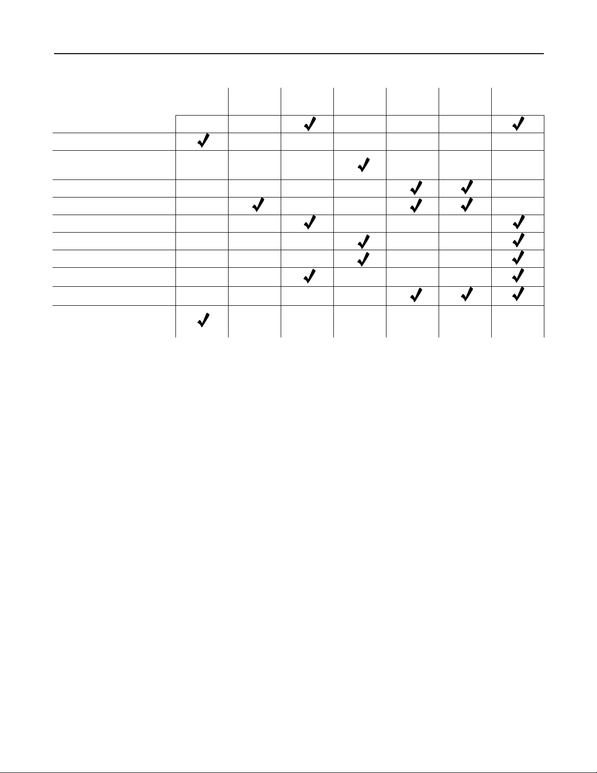
SECTION 11: MAINTENANCE CHART
Clean Hood/Dash Louvers
Check Engine Oil Level
Clean and Re-oil Air
Filter’s Foam Precleaner
Replace Air Filter Element
Change Engine Oil & Filter
Clean Battery Terminals
Lube Front Axles and Rims
Clean Engine Cooling Fins
Lube Pedal Pivot Points
Check Spark Plug
Check Safety Interlock
System
Before
Each Use
After Initial
24 Hours
Every
10 Hours
Every
25 Hours
Every
100 Hours
Every
Season
Prior
to Storing
28
Page 29

SECTION 12: TROUBLESHOOTING
Trouble Possible Cause(s) Corrective Action
Engine fails to start PTO (Blade Engage) lever engaged.
Parking brake not engaged.
Spark plug wire(s) disconnected.
Throttle/choke control not in correct
starting position.
Choke not activated
Fuel tank empty, or stale fuel.
Blocked fuel line.
Faulty spark plug.
Engine flooded.
Engine runs erratic Unit running with CHOKE activated.
Spark plug wire(s) loose.
Blocked fuel line or stale fuel.
Vent in gas cap plugged.
Water or dirt in fuel system.
Dirty air cleaner.
Engine overheats Engine oil level low.
Air flow restricted.
Engine hesitates at high RPM Spark plug gap too close. Remove spark plug and reset the gap.
Idles poorly Spark plug fouled, faulty or gap too
wide.
Dirty air cleaner.
Excessive vibration Cutting blade loose or unbalanced.
Damaged or bent cutting blade.
Mower will not mulch grass Engine speed too low.
Wet grass.
Excessively high grass.
Dull blade.
Uneven cut Deck not balanced properly.
Dull blade.
Uneven tire pressure.
Place PTO (Blade Engage) Lever in disengaged (OFF)
position.
Engage parking brake.
Connect wire to spark plug.
Move Throttle/Choke Control into CHOKE position.
Move Throttle/Choke Control into CHOKE position.
Fill tank with clean, fresh (less than 30 days old) gas.
Clean fuel line or replace fuel filter.
Clean, adjust gap or replace plug.
Crank engine with throttle in FAST position.
Move Throttle/Choke Control out of CHOKE position.
Connect and tighten spark plug wire(s).
Clean fuel line; fill tank with clean, fresh (less than 30
days old) gasoline. Replace fuel filter, if so equipped.
Clear vent or replace cap if damaged.
Drain fuel tank. Refill with clean, fresh (less than 30
days old) gasoline.
Replace air cleaner paper element or clean foam
precleaner.
Fill crankcase with proper capacity and weight of oil.
Clean grass clippings and debris from around the
engine’s cooling fins and blower housing.
Replace spark plug. Set plug gap.
Replace air cleaner element or clean pre-cleaner.
Tighten blade and spindle. Balance blade.
Replace blade.
Place throttle in FAST (rabbit) position.
Do not mow when grass is wet; wait until later to cut.
Mow once at a high cutting height, then mow again at
desired height or make a narrower cutting swath.
Sharpen or replace blade.
Perform side-to-side deck adjustment.
Sharpen or replace blade.
Check tire pressure in all four tires.
29
Page 30

SECTION 13: SPECIFICATIONS*
Capacities
Fuel Tank 3.0 gal. (11.4 liters) 3.0 gal. (11.4 liters)
Engine Crankcase (w/ filter) 50.75 oz. (1.5 liters) 50.75 oz. (1.5 liters)
Constant Velocity Transmission
Forward Speed 0 m.p.h. - 5.2 m.p.h.
Reverse Speed 0 m.p.h. - 2.3 m.p.h. 0 m.p.h. - 2.3 m.p.h.
Engine (Air-cooled, 4-cycle)
Make Kohler Courage Kohler Courage
Model SV540 SV600
Cylinders Single Single
Bore 3.50 in. (89 mm) 3.70 in. (94 mm)
Stroke 3.38 in. (86 mm) 3.38 in. (86 mm)
Displacement 32.6 cubic in. (535 cc) 36.4 cubic in. (597 cc)
Power @3600 RPM 18 HP (13.4 kW)** 20 HP (14.9 kW)**
Maximum Torque 32.1 ft. lb. (43.5 Nm)
Compression Ratio 8.5:1 8.5:1
Engine Speed (governed) 3375 RPM 3375 RPM
Low Speed 1500 RPM (± 75 RPM) 2150 RPM (± 75 RPM)
Spark Plug Gap .76 mm (.030 in.) .76 mm (.030 in.)
Electrical System
System Voltage 12-volt Negative Ground 12-volt Negative Ground
Battery 190 CCA (sealed) 190 CCA (sealed)
Alternator 15 Amp Regulated 15 Amp Regulated
Fuse (automotive type) 20 Amp 20 Amp
Headlights Incandescent Incandescent
Brakes
Turf Tires
Front (inches) 15 x 6 x 6 15 x 6 x 6
Rear (inches) 20 x 8 x 8 20 x 8 x 8
Dimensions
Cutting Width, Deck 42 in. (106.7 cm) 46 in. (116.8 cm)
Wheelbase 46 in. (116.8 cm) 46 in. (116.8 cm)
Length, over all 68 in. (172.7 cm)
Width, over all 45 in. (114.3 cm) 13.2 liters (3.5 gallons)
Height, over all 43 in. (109.2 cm) 1.5 liters (50.75 oz.)
Ground Clearance 4.5 in. (11.4 cm) 4.5 in. (11.4 cm)
Turning Radius 18 in. (46 cm) 18 in. (46 cm)
Weight (approximate) 498 lb. (225.9 kg) 501 lb. (227.25 kg.)
LX420 LX460
0 m.p.h. - 5.2 m.p.h.
@ 2200 RPM
Single Disc (Dry) Single Disc (Dry)
36.9 ft. lb. (50.0 Nm)
@ 2200 RPM
68 in. (172.7 cm)
* Toro reserves the right to change product specifications, design, and standard equipment without notice and without incurring obligation
** Kohler’s horsepower ratings exceed Society of Automotive Engineers Small Engine Test Code J1940. Actual engine horsepower is lower and
affected by, but not limited to, accessories (air cleaner, exhaust, charging, cooling, fuel pump, etc.), application, engine speed and ambient
operating conditions (temperature, humidity, and altitude).
30
Page 31

Evaporative Emission Control Warranty Statement
Y
t
California Evaporative Emission Control Warranty Statement
Your Warranty Rights and Obligations
Introduction
The California Air Resources Board and The Toro® Company are pleased to explain the evaporative emission control system’s warranty on your 2006 model
year equipment. In California, new equipment that use small off-road engines must be designed, built, and equipped to meet the State’s stringent anti-smog
standards. The Toro® Company must warrant the evaporative emission control system on your equipment for two years provided there has been no abuse,
neglect or improper maintenance of your equipment.
our evaporative emission control system may include parts such as: fuel lines, fuel line fittings, and clamps.
This evaporative emission control system is warranted for two years. If any evaporative emission-related part on your equipment is defective, the part will be
repaired or replaced by The Toro® Company.
Manufacturer’s Warranty Coverage:
Owner’s Warranty Responsibilities:
• As the equipment owner, you are responsible for performance of the required maintenance listed in your Operator’s Manual. The Toro® Company recommends
that you retain all receipts covering maintenance on your equipment, but The Toro® Company cannot deny warranty solely for the lack of receipts.
• As the equipment owner, you should however be aware that The Toro® Company may deny you warranty coverage if your emission warranty parts have failed
due to abuse, neglect, or improper maintenance or unapproved modifications.
• You are responsible for presenting your equipment to an Authorized Service Dealer as soon as the problem exists. The warranty repairs should be completed
in a reasonable amount of time, not to exceed 30 days. If you have a question regarding your warranty coverage, you should contact The Toro® Company at
1-952–948–4027 or call us toll free at the number listed in your Toro Warranty statement.
Defects Warranty Requirements:
1. The warranty period begins on the date the engine or equipment is delivered to an ultimate purchaser.
2. General Evaporative Emissions Warranty Coverage. The emission warranty parts must be warranted to the ultimate purchaser and any subsequent owner tha
the evaporative emission control system when installed was:
A. Designed, built, and equipped so as to conform with all applicable regulations; and
B. Free from defects in materials and workmanship that causes the failure of a warranted part for a period of two years.
3. The warranty on evaporative emissions-related parts will be interpreted as follows:
A. Any warranted part that is not scheduled for replacement as required maintenance in the written instructions must be warranted for the warranty period
of two years. If any such part fails during the period of warranty coverage, it must be repaired or replaced by The Toro® Company. Any such part
repaired or replaced under the warranty must be warranted for a time not less than the remaining warranty period.
B. Any warranted part that is scheduled only for regular inspection in the written instructions must be warranted for the warranty period of two years. A
statement in such written instructions to the effect of “repair or replace as necessary” will not reduce the period of warranty coverage. Any such part
repaired or replaced under warranty must be warranted for a time not less than the remaining warranty period.
C. Any warranted part that is scheduled for replacement as required maintenance in the written instructions must be warranted for the period of time
prior to the first scheduled replacement point for that part. If the part fails prior to the first scheduled replacement, the part must be repaired or
replaced by The Toro® Company. Any such part repaired or replaced under warranty must be warranted for a time not less than the remainder of
the period prior to the first scheduled replacement point for the part.
D. Repair or replacement of any warranted part under the warranty provisions of this article must be performed at no charge to the owner at an Authorized
Service Dealer.
E. Notwithstanding the provisions of subsection (D) above, warranty services or repairs must be provided at an Authorized Service Dealer.
F. The owner must not be charged for diagnostic labor that leads to the determination that a warranted part is in fact defective, provided that such
diagnostic work is performed at an Authorized Service Dealer.
G. Throughout the evaporative emission control system’s two year warranty period, The Toro® Company must maintain a supply of warranted parts
sufficient to meet the expected demand for such parts.
H. Manufacturer approved replacement parts must be used in the performance of any warranty maintenance or repairs and must be provided without
charge to the owner. Such use will not reduce the warranty obligations of The Toro® Company.
I. The use of any add-on or modified parts will be grounds for disallowing a warranty claim made in accordance with this article. The Toro® Company will
not be liable under this Article to warrant failures of warranted parts caused by the use of an add-on or modified part.
J. The Toro® Company shall provide any documents that describe the warranty procedures or policies within five working days of request by the Air
Resources Board.
Emission Warranty Parts List:
The following lists includes the parts covered under this warranty:
• Fuel Lines
• Fuel Line Fittings
• Clamps
31
374-0092 Rev A
Page 32

The Toro company
MANUFACTURER’S LIMITED WARRANTY FOR
LAWN & GARDEN TRACTORS
IMPORTANT: To obtain warranty coverage owner must present an original
proof of purchase and applicable maintenance records to the servicing dealer.
Please see the operator’s manual for information on required maintenance and
service intervals.
The limited warranty set forth below is given by The Toro Company (“Toro”)
with respect to new merchandise purchased or leased and used in the United
States and/or its territories and possessions, and by Toro with respect to new
merchandise purchased or leased and used in Canada and/or its territories and
possessions.
Toro warrants this product (excluding its Normal Wear Parts, Batteries, and
Frame and Front Axle as described below) against defects in material and
workmanship for a period of three (2) years or eighty (80) operation hours,
whichever comes first, commencing on the date of original retail purchase or
lease and will, at its option, repair or replace, free of charge, any part found to
be defective in materials or workmanship.
Normal Wear Parts are warranted to be free from defects in material and
workmanship for a period of thirty (30) days from the date of original purchase
or lease. Normal wear parts include, but are not limited to items such as: belts,
blades, blade adapters, grass bags, rider deck wheels, seats, and tires.
Batteries have a one-year prorated limited warranty against defects in material
and workmanship, with 100% replacement during the first three months. After
three months, the battery replacement credit is based on the months remaining
in the twelve (12) month period dating back to the original date of original sale
or lease. Any replacement battery will be warranted only for the remainder of
the original warranty period.
Frame and Front Axle — Toro warrants the frame, and front cast iron pivot axle
against defects in material and workmanship for a period of five (5) years or
500 hours, whichever occurs first, commencing on the date of original purchase
or lease.
This limited warranty shall only apply if this product has been operated and
maintained in accordance with the Operator’s Manual furnished with the
product, and has not been subject to misuse, abuse, commercial use, neglect,
accident, improper maintenance, alteration, vandalism, theft, fire, water, or
damage because of other peril or natural disaster. Damage resulting from the
installation or use of any part, accessory or attachment not approved by Toro
for use with the product(s) covered by this manual will void your warranty as
to any resulting damage. In addition, Toro may deny warranty coverage if the
hour meter, or any part thereof, is altered, modified, disconnected or otherwise
tampered with.
HOW TO OBTAIN SERVICE : Warranty service is available, WITH PROOF OF
PURCHASE AND APPLICABLE MAINTENANCE RECORDS, through your
local authorized service dealer. To locate the dealer in your area:
In the U.S.A. or Canada:
Check your Yellow Pages, or contact The Customer Care Department, a Toro
Warranty Company at 8111 Lyndale Avenue South, Bloomington, MN 55420,
call 1-888-384-9942 (In Canada 1-888-848-4073).
or log on to our website at www.toro.com.
Without limiting the foregoing, this limited warranty does not provide coverage
in the following cases:
a. The engine or component parts thereof. These items may carry a separate
manufacturer’s warranty. Refer to applicable manufacturer’s warranty for
terms and conditions.
b. Routine maintenance items such as lubricants, filters, blade sharpening,
tune-ups, brake adjustments, clutch adjustments, deck adjustments, and
normal deterioration of the exterior finish due to use or exposure.
c. Service completed by someone other than an authorized service dealer.
d. Toro does not extend any warranty for products sold or exported outside
of the United States and/or Canada, and their respective possessions and
territories, except those sold through Toro’s authorized channels of export
distribution.
e. Replacement parts and/or accessories that are not genuine Toro parts.
f. Transportation charges and service calls.
g. Toro does not warrant this product for commercial use.
There are no implied warranties, including without limitation any implied
warranty of merchantability or fi tness for a particular purpose. No
warranties shall apply after the applicable period of express written
warranty above. No other express warranties beyond those mentioned
above, given by any person or entity, including a dealer or retailer, with
respect to any product, shall bind Toro. The exclusive remedy is repair or
replacement of the product as set forth above. The terms of this warranty
provide the sole and exclusive remedy arising from the sale and/or lease
of the products covered hereby. Toro shall not be liable for any incidental
or consequential loss or damage including, without limitation, expenses
incurred for substitute or replacement lawn care services or for rental
expenses to temporarily replace a warranted product.
Some jurisdictions do not allow the exclusion or limitation of incidental or
consequential damages, or limitations on how long an implied warranty lasts,
so the above exclusions or limitations may not apply to you.
In no event shall recovery of any kind be greater than the amount of the
purchase price of the product sold. Alteration of safety features of the
product shall void this warranty.
damage, or injury to you and your property and /or to others and their property
arising out of the misuse or inability to use the product.
This limited warranty shall not extend to anyone other than the original
purchaser or to the person for whom it was purchased as a gift.
HOW LOCAL LAWS RELATE TO THIS WARRANTY: This limited warranty
gives you specific legal rights, and you may also have other rights that vary in
different jurisdictions.
You assume the risk and liability for loss,
Customer Care Department of the Toro Warranty Company, 8111 Lyndale Ave. South,
Bloomington, MN 55420-1196 or call (US) 1-888-384-9942, (Canada) 1-888-848-4073; www.toro.com
32
 Loading...