


FormNo.3425-123RevA
BoreDriveAttachment
TRXTrencher
ModelNo.22978—SerialNo.310000001andUp
Registeratwww.T oro.com.
OriginalInstructions(EN)
*3425-123*A
WARNING
CALIFORNIA
Proposition65Warning
Useofthisproductmaycauseexposure
tochemicalsknowntotheStateof
Californiatocausecancer,birthdefects,
orotherreproductiveharm.
Introduction
ThismachineisanattachmentforaTRXtrencher
intendedforusebylandscapeprofessionalsand
rentalequipmentoperators.Itisdesignedforboring
holesthroughsoilunderdrivesandsidewalksandfor
pullingcablingandpipingthroughtheboredholes.
Itisnotdesignedforboringthroughrockorother
non-soildebris.Usingthisproductforpurposesother
thanitsintendedusecouldprovedangeroustoyou
andbystanders.
Readthisinformationcarefullytolearnhowtooperate
andmaintainyourproductproperlyandtoavoid
injuryandproductdamage.Youareresponsiblefor
operatingtheproductproperlyandsafely .
Visitwww.T oro.comformoreinformation,including
safetytips,trainingmaterials,accessoryinformation,
helpndingadealer,ortoregisteryourproduct.
Wheneveryouneedservice,genuineToroparts,or
additionalinformation,contactanAuthorizedService
DealerorToroCustomerServiceandhavethemodel
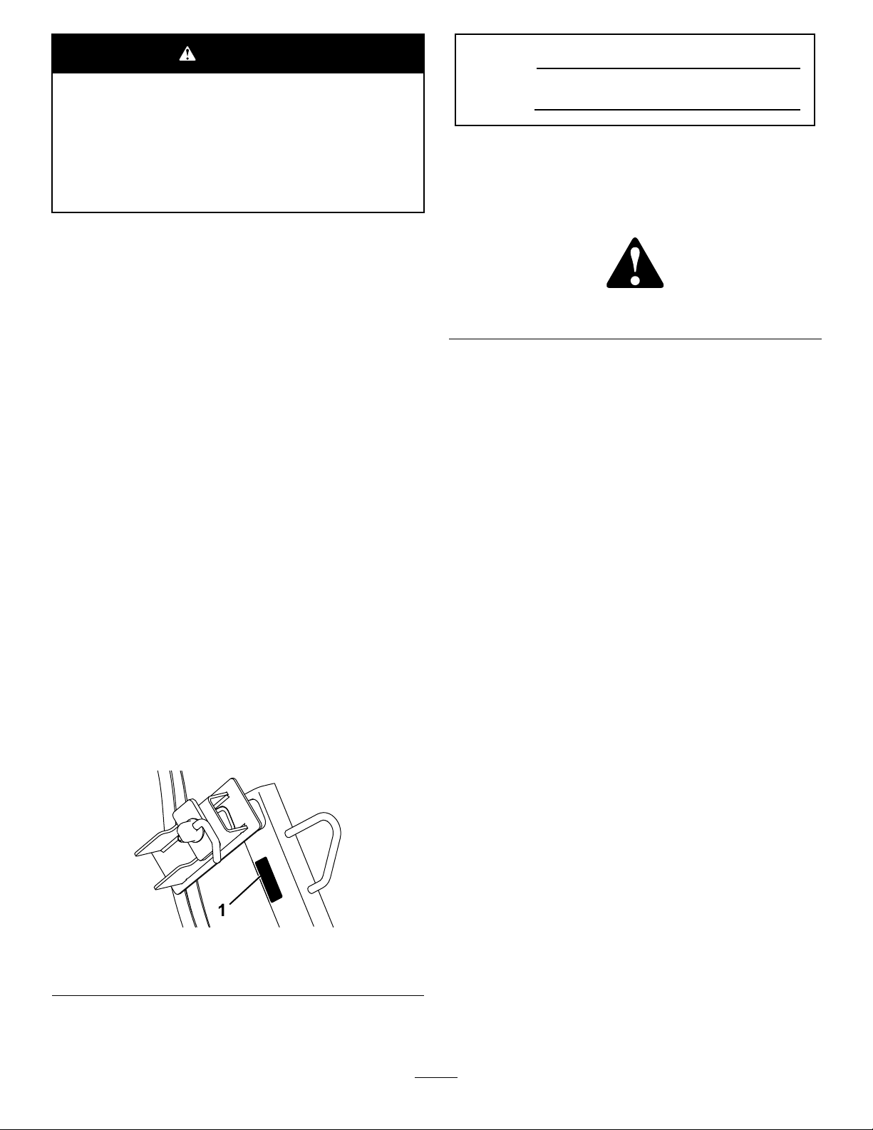
andserialnumbersofyourproductready.Figure1
identiesthelocationofthemodelandserialnumbers
ontheproduct.Writethenumbersinthespace
provided.
ModelNo.
SerialNo.
Thismanualidentiespotentialhazardsandhas
safetymessagesidentiedbythesafety-alertsymbol
(Figure2),whichsignalsahazardthatmaycause
seriousinjuryordeathifyoudonotfollowthe
recommendedprecautions.
g000502
Figure2
Thismanualuses2wordstohighlightinformation.
Importantcallsattentiontospecialmechanical
informationandNoteemphasizesgeneralinformation
worthyofspecialattention.
Contents
Safety.......................................................................3
GeneralSafety...................................................3
BoreDriveSafety...............................................3
HydraulicSystemSafety.....................................4
SafetyandInstructionalDecals..........................4
Setup........................................................................5
1PreparingtheMachine.....................................5
2DisconnectingtheExistingHydraulic
Hoses..............................................................6
3InstallingtheHydraulicManifold.......................9
4ConnectingtheHydraulicHoses......................9
5CheckingtheHydraulics.................................11
6AssembletheRodGuide...............................12
7ConnectingtheDriveHeadtothe
Trencher.......................................................12
ProductOverview...................................................13
Specications..................................................13
Operation................................................................14
InstallinganAccessory.....................................14
RemovinganAccessory...................................14
BoringaHole....................................................14
Storage...................................................................16
1.Locationofthemodelandserialnumbers
©2019—TheToro®Company
8111LyndaleAvenueSouth
Bloomington,MN55420
Figure1
g278521
Contactusatwww.Toro.com.
2
PrintedintheUSA
AllRightsReserved

Safety
DANGER
Theremaybeburiedutilitylinesinthework
area.Diggingintothemmaycauseashock
oranexplosion.
Havethepropertyorworkareamarkedfor
buriedlinesanddonotdiginmarkedareas.
Contactyourlocalmarkingserviceorutility
companytohavethepropertymarked(for
example,intheUS,call811orinAustralia,
call1100forthenationwidemarkingservice).
GeneralSafety
Thisproductiscapableofamputatinghandsandfeet.
Alwaysfollowallsafetyinstructionstoavoidserious
injuryordeath.Usingthisproductforpurposesother
thanitsintendedusecouldprovedangeroustoyou
andbystanders.
•Havethepropertyorworkareamarkedforburied
linesandotherobjects,anddonotdiginmarked
areas.
•Keepyourhandsandfeetawayfrommoving
teeth,auger,orotherparts.
•Keepbystandersandpetsawayfromthemachine.
•ReadandunderstandthecontentofthisOperator’s
Manualbeforestartingtheengine.
•Neverallowchildrenoruntrainedpeopleto
operatethemachine.
•Donotoperatethemachinewithouttheguards
andothersafetyprotectivedevicesinplaceand
workingonthemachine.
•Useyourfullattentionwhileoperatingthe
machine.Donotengageinanyactivitythat
causesdistractions;otherwise,injuryorproperty
damagemayoccur.
•Stopthemachine,shutofftheengine,andremove
thekeybeforeservicing,fueling,orunclogging
themachine.
BoreDriveSafety
•Rotatingrodandbitscanentanglelooseclothing,
hands,arms,legs,andfeet,causingdeathor
seriousinjury.
–Keepatleast3m(10ft)fromrotatingparts,
unlessyouareoperatingtherodguidetool.
–Useonlytherodguidetooltostarttherodand
boringbit.
–Keepextremitiesandotherpartsofyourbody
orclothingawayfromrotatingparts.
–Neverstraddleorstandontherodwhenthe
engineisrunning.
–Donotwearlooseclothingorjewelrywhile
operatingorassistingwiththeboringunit.
–Usecautionwhenstandingnexttotrenches
andbeawareofweakorcollapsingtrench
walls.
–Alwaysshutofftheengineandremovethekey
beforechangingaccessories.
–Donotservicetheattachmentunlessrod
rotationisstopped,thehydraulicsleverisin
neutral,andtheengineisstopped.
–Donotuseboltsorpinsinplaceofpushbutton
connectors.
•Hydrauliccouplers,hydrauliclines/valves,and
hydraulicuidmaybehotandcanburnyouifyou
touchthem.
–Weargloveswhenoperatingthehydraulic
couplers.
–Allowthetractionunittocoolbeforetouching
hydrauliccomponents.
–Donottouchhydraulicuidspills.
•Alwaysuse2peopletooperatetheattachment,1
tooperatethetractionunitandtheothertoguide
theboringunitwiththeguidetool.
•Lightningcancausesevereinjuryordeath.If
lightningisseenorthunderisheardinthearea,do
notoperatethemachine;seekshelter.
Improperlyusingormaintainingthismachinecan
resultininjury.Toreducethepotentialforinjury,
complywiththesesafetyinstructionsandalwayspay
attentiontothesafety-alertsymbol,whichmeans
Caution,Warning,orDanger—personalsafety
instruction.Failuretocomplywiththeseinstructions
mayresultinpersonalinjuryordeath.
Youcanndadditionalsafetyinformationwhere
neededthroughoutthismanual.
3

HydraulicSystemSafety
SafetyandInstructional
•Seekimmediatemedicalattentionifuidisinjected
intoskin.Injecteduidmustbesurgicallyremoved
withinafewhoursbyadoctor.
•Ensurethatallhydraulic-uidhosesandlinesare
ingoodconditionandallhydraulicconnections
andttingsaretightbeforeapplyingpressureto
thehydraulicsystem.
•Keepyourbodyandhandsawayfrompinhole
leaksornozzlesthatejecthigh-pressurehydraulic
uid.
•Usecardboardorpapertondhydraulicleaks.
•Safelyrelieveallpressureinthehydraulicsystem
beforeperforminganyworkonthehydraulic
system.
Decals
Safetydecalsandinstructionsare
easilyvisibletotheoperatorandare
locatednearanyareaofpotential
danger.Replaceanydecalthatis
damagedormissing.
decal117-8855
117-8855
1.Boredriveoperation2.Trencheroperation
1.Warning—readthe
Operator’sManual.
2.Entanglementhazard,
shaft—keepbystanders
away.
4
decal117-9952
117-9952
3.Explosionhazard;
electricalshock
hazard—donotoperate
ifpowerlinesmaybe
present.

Setup
LooseParts
Usethechartbelowtoverifythatallpartshavebeenshipped.
ProcedureDescription
1
2
3
4
5
6
Nopartsrequired
Nopartsrequired
Manifoldbracket
Carriagebolt(5/16x1inch)
Locknut(5/16inch)
Hydraulicmanifoldassembly
Hexsocket-headbolt(5/16x3-1/4
inches)
Hydraulichosewithshortelbowtting
(TRX-16,TRX-20,andTRX-26only)
Hydraulichosewithlongelbowtting
(TRX-16,TRX-20,andTRX-26only)
Longhydraulichosewithstraightttings
Shorthydraulichosewithstraightttings
(TRX-250andTRX-300only)
Nopartsrequired
Rodguide,lowerhalf
Rodguide,upperhalf
Rollpin1
Qty.
Use
–
–
1
1
3
1
2
1
1
2
2
–
1
1
Preparethemachine.
Disconnecttheexistinghydraulichoses.
Installthehydraulicmanifold.
Connectthehydraulichoses.
Checkthehydraulics
Assembletherodguide.
7
Determinetheleftandrightsidesofthemachinefrom
thenormaloperatingposition.
Drivehead1
1
PreparingtheMachine
NoPartsRequired
Procedure
1.Parkthemachineonalevelsurface,engagethe
parkingbrake,andlowertheboom.
2.Shutofftheengineandremovethekey.
3.Allowthemachinetocoolfully.
Connectthedriveheadtothetrencher.
5

2
DisconnectingtheExisting
HydraulicHoses
NoPartsRequired
TRX-16,TRX-20,andTRX-26
Note:Thisprocedurecausessomehydraulicuid
leakage.Ensurethatyouperformitinanarea
equippedtocatchoreasilycleanspilledhydraulic
uid.
CAUTION
Hydrauliccouplers,hydrauliclines/valves,
andhydraulicuidmaybehot.Ifyoucontact
hotcomponents,youmaybeburned.
•Weargloveswhenoperatingthehydraulic
couplers.
3.Removethereferencebar(Figure4)
g011656
Figure4
1.Referencebar
4.Disconnectthespringfromthehydraulicslever
andremoveitasshowninFigure5.
•Allowthemachinetocoolbeforetouching
hydrauliccomponents.
•Donottouchhydraulicuidspills.
1.Movethehydraulicleverbackandforthafew
timestorelieveanypressureinthelines.
2.Removethetraction-controlhandle(Figure3).
g011657
Figure5
1.Hydraulicslever
1.Traction-controlhandle
g011655
Figure3
6

5.Threadtheknoboffoftheboom-controllever
(Figure6).
g011658
Figure6
1.Boom-controlleverlock2.Boom-controlleverknob
6.Fromunderthecontrolpanel,removethehairpin
cotterandwasherthatsecuretheboom-control
leverlockandremovethelock(Figure6)
7.RemovethecontrolpanelasshowninFigure7.
8.DisconnectthehydraulichosesshowninFigure
8fromthehydraulicslevervalve.
g279761
Figure8
Figure7
1.Upperhydraulichose2.Lowerhydraulichose
9.Disconnectthehydraulichosesfromthe
hydraulicmotoronthetrencher(Figure12).
g011659
g011661
Figure9
1.Hydraulicmotor
2.Righthydraulichose
3.Lefthydraulichose
10.Removeanddiscardthebolt,nut,andhose
clampsecuringthehosestothetrencherframe.
11.Removeanddiscardthehydraulichosesyou
disconnectedfromthemachine.
7

TRX-250andTRX-300
Note:Thisprocedurecausessomehydraulicuid
leakage.Ensurethatyouperformitinanarea
equippedtocatchoreasilycleanspilledhydraulic
uid.
CAUTION
Hydrauliccouplers,hydrauliclines/valves,
andhydraulicuidmaybehot.Ifyoucontact
hotcomponents,youmaybeburned.
•Weargloveswhenoperatingthehydraulic
couplers.
•Allowthemachinetocoolbeforetouching
hydrauliccomponents.
3.Disconnectthehydraulichosesfromthe
hydraulicmotoronthetrencher(Figure12).
•Donottouchhydraulicuidspills.
1.Removetherearguard(Figure10).
Figure10
1.Rearguard
2.DisconnectthehydraulichosesshowninFigure
11fromthehydraulicslevervalve.
2.Hex-angebolt—3/8x1
inch(2)
g011661
Figure12
1.Hydraulicmotor3.Righthydraulichose
2.Lefthydraulichose
4.Removeanddiscardthebolt,nut,andhose
clampsecuringthehosestothetrencherframe.
5.Removeanddiscardthehydraulichosesyou
disconnectedfromthemachine.
g279888
1.Lefthydraulichose
g279887
Figure11
2.Righthydraulichose
8

3
InstallingtheHydraulic
Manifold
Partsneededforthisprocedure:
1
Manifoldbracket
1
Carriagebolt(5/16x1inch)
3
Locknut(5/16inch)
1
Hydraulicmanifoldassembly
2
Hexsocket-headbolt(5/16x3-1/4inches)
Procedure
1.Usingacarriagebolt(5/16x1inch)andlocknut
(5/16inch),installthemanifoldbrackettothe
trencherframeintheholethatyouopenedwhen
youremovedthehoseclamp(Figure13).
g011663
Figure14
1.Hydraulicmanifold
4
ConnectingtheHydraulic
Hoses
Figure13
1.Manifoldbracket
2.Installthehydraulicmanifoldtothemanifold
bracketusing2hexsocket-headbolts(5/16
x3-1/4inches)and2locknuts(5/16inch)as
showninFigure14.
Partsneededforthisprocedure:
Hydraulichosewithshortelbowtting(TRX-16,
1
TRX-20,andTRX-26only)
Hydraulichosewithlongelbowtting(TRX-16,
1
TRX-20,andTRX-26only)
2
Longhydraulichosewithstraightttings
Shorthydraulichosewithstraightttings(TRX-250
2
andTRX-300only)
g011662
TRX-16,TRX-20,andTRX-26
1.Routethehydraulichosewiththeshortelbow
ttingononeendfromthehydraulicmanifoldto
thehydrauliclevervalve,withtheelbowtting
nearthehydrauliclevervalve.
2.Connecttheshortelbowttingtothebottomport
onthevalve(Figure15).
9

Figure15
7.Connectalonghosewithstraightttingstoeach
ofthe2openportsonthefrontofthehydraulic
manifold.
Note:Theshorthydraulichosesare103cm
(40-1/2inches)long.Thelonghosesare105
cm(41-1/2inches)long.
8.Loopthehosesupandaroundsothattheopen
ttingsareattheopenportsonthehydraulic
motoronthetrencher(Figure16).
9.Connectthelefthosetothelowerportonthe
motor(Figure17).
g279761
1.Hydraulichosewiththe
longelbowtting
2.Hydraulichosewiththe
shortelbowtting
3.ConnectthestraightendofthehosetoportT
(rightport)onthebackofthehydraulicmanifold
(Figure16).
Figure16
1.PortT2.PortP
4.Routethehydraulichosewiththelongelbow
ttingfromthehydraulicmanifoldtothe
hydrauliclevervalve,withtheelbowttingnear
thehydrauliclevervalve.
5.Connectthelongelbowttingtothetopporton
thevalve(Figure15).
g011661
Figure17
1.Hydraulicmotor3.Routethishosetothe
2.Routethishosetothe
rightsideofthehydraulic
manifold.
leftsideofthehydraulic
manifold.
10.Connecttherighthosetotheupperportonthe
motor(Figure17).
11.Ensurethatallhosesaretightenedsecurely.
TRX-250andTRX-300
g011664
1.Routetheshorthydraulichoseswithstraight
ttingsfromthehydraulicmanifoldtothe
hydrauliclevervalve.
Note:Theshorthydraulichosesare103cm
(40-1/2inches)long.Thelonghosesare105
cm(41-1/2inches)long.
2.Connectthestraightttingstotheemptyports
onthehydrauliclevervalve(Figure18).
6.ConnectthestraightendofthehosetoportP
(leftport)onthebackofthehydraulicmanifold
(Figure16).
10

Figure18
g279887
1.Lefthydraulichose
3.ConnecttheotherendofthelefthosetoportT
(rightport)onthebackofthehydraulicmanifold
andtheotherendoftherighthosetoportP(left
port)asshowninFigure19.
2.Righthydraulichose
Figure19
g011661
Figure20
1.Hydraulicmotor3.Routethishosetothe
2.Routethishosetothe
rightsideofthehydraulic
manifold.
7.Connecttherighthosetotheupperportonthe
motor(Figure20).
8.Ensurethatallhosesaretightenedsecurely .
leftsideofthehydraulic
manifold.
5
CheckingtheHydraulics
g011664
NoPartsRequired
1.PortT2.PortP
4.Connectthelonghoseswithstraightttingsto
the2openportsonthefrontofthehydraulic
manifold.
5.Loopthehosesupandaroundsothattheopen
ttingsareattheopenportsonthehydraulic
motoronthetrencher(Figure19).
6.Connectthelefthosetothelowerportonthe
motor(Figure20).
Procedure
1.ForTRX-16,TRX-20,andTRX-26,installthe
controlpanelasfollows:
A.PlacethecontrolpanelasshowninFigure
7.
B.Installtheboom-controlleverlockand
secureitwiththehairpincotterandwasher
youremovedpreviously(Figure6).
C.Installtheknobontheboom-controllever
(Figure6).
D.Installthehydraulicsleverasshownin
Figure5,thenattachthespring.
E.Installthetractionhandleandreferencebar
together(Figure3andFigure4).
Important:Pullthetractionhandle
tightagainstthereferencebarwhenyou
tightenittoensurethatthemachine
tracksstraightwhennished.
11
2.ForTRX-250andTRX-300,installtherear
guard(Figure10).
3.Starttheengine,raisetheboom,andoperate
thetrencherchainforafewseconds.
4.Shutofftheengineandremovethekey.
5.Checkallconnectionsforleaks.
6.Checkthehydraulicuidlevelandadduidif
necessary;refertotheOperator’sManualfor
themachine.
6
AssembletheRodGuide
Partsneededforthisprocedure:
1
Rodguide,lowerhalf
1
Rodguide,upperhalf
1Rollpin
7
ConnectingtheDriveHead
totheTrencher
Partsneededforthisprocedure:
1Drivehead
Procedure
1.Starttheengineandraisetheboomtothe
highestposition.
2.Shutoftheengine,removethekey ,andmove
theboom-controllocklevertothelocked
position.
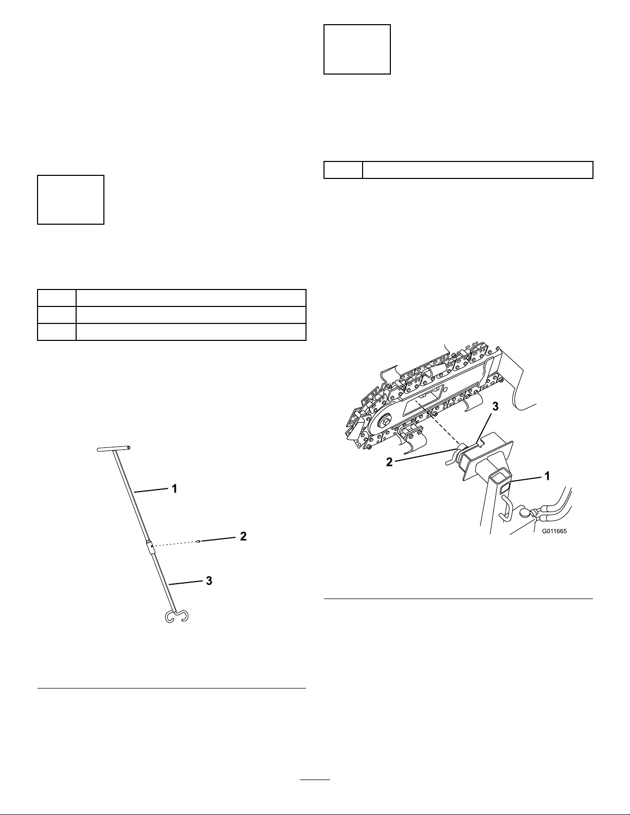
3.Loosenthelever-lockboltonthedriveheadand
turntheclampplatesothatitisparalleltothe
drivehead(Figure22).
Procedure
1.Slidetheupperhalfoftherodguideintothe
socketofthelowerhalf,ensuringthattheholes
align.
2.Securetheconnectionwitharollpin(Figure21).
Figure21
1.Upperhalfofrodguide3.Lowerhalfofrodguide
2.Rollpin
g011665
Figure22
1.Bore-drivehead
2.Lever-lockbolt
4.Slidethebore-driveheadthroughtheopeningin
g279774
thetrencherboomasshowninFigure22.
5.Rotatetheclampplate90degreesandtighten
thelever-lockbolt;ipthelevertolockitinplace
(Figure23).
3.Clampplate
12

ProductOverview
Specications
Specicationsanddesignaresubjecttochange
withoutnotice.
Figure23
1.Clampplate
2.Lever-lockbolt
6.Movethehydraulicsleverbackandforthafew
timestorelievepressureinthesystem.
7.Lowertheswitchingleveronthehydraulic
manifoldtoswitchfromtrencheroperationto
boredriveheadoperation(Figure24).
Weight
Boringdiameter3.2to8.9cm
g011666
30kg(60lb)
(1-1/4to3-1/2inches)
Toensureoptimumperformanceandcontinuedsafety
certicationofthemachine,useonlygenuineT oro
replacementpartsandaccessories.Replacement
partsandaccessoriesmadebyothermanufacturers
couldbedangerous,andsuchusecouldvoidthe
productwarranty.
Figure24
1.Switchinglever(showninboredriveoperationposition)
8.Connectthemaleandfemalecouplerson
theboredriveheadhosestotheappropriate
couplersonthehydraulicmanifold.
Toremovetheboredrivehead,raisetheboomtothe
highestposition,shutoffthemachine,removethe
key,movetheboom-controlleverlocktothelocked
position,andreversethisprocedure.
g011800
13

Operation
BoringaHole
InstallinganAccessory
Torooffersseveraldifferentrodsandbitsforusewith
theattachment.Purchaseaccessoriesfromyour
AuthorizedT oroDealer.
1.Parkthemachineonalevelsurface,engagethe
parkingbrake,andlowertheboom.
2.Shutofftheengineandremovethekey.
3.Slidethehexshaftofarod,boringbit,orreamer
intothesocket.Aligntheholeinthesocketwith
thepush-buttonconnector(Figure25).
DiggingtheTrenches
Beforedrillingunderawalkordriveway,makean
entranceandanexittrenchoneithersideofthe
drillingarea(Figure26).
•Bothtrenchesmustbeatleast15.2cm(6inches)
wideand45.7cm(18inches)deep.
•Theentrancetrenchmustbeatleast2.1m(7ft)
longandperpendiculartothewalkordriveway.
•Theexittrenchmustbe0.9to1.8m(3to6ft)
long,paralleltothewalkordriveway,andcentered
acrosstheentrancetrench.
Figure25
1.Accessoryshaft
2.Socket
4.Pressdownthepush-buttonconnectorand
pushtheshaftintothesocketuntiltheconnector
snapsintotheholeinthesocket(Figure25).
5.Repeatsteps3and4asneededtoaddparts.
3.Push-buttonconnector
4.Hole
RemovinganAccessory
1.Parkthemachineonalevelsurface,engagethe
parkingbrake,andlowertheboom.
2.Shutofftheengineandremovethekey.
3.Pressdownthepush-buttonconnectorsecuring
theaccessoryshaftinthesocketandpullthe
accessoryoutofthesocket.
g008475
1.Entrancetrench3.Exittrench
2.Sidewalk
Figure26
g008476
BoringtheHole
Important:Boringaholerequires2people.Do
notattempttoperformthisoperationbyyourself.
1.Positionthetractionunitwiththedriveheadat
thebeginningofthetrench
2.Shutofftheengine,removethekey,andwaitfor
allmovingpartstostop.
3.Connectarodandboringbitontothedrive
head;refertoInstallinganAccessory(page14).
4.Connecttherodguidetotherodjustbehindthe
boringbit(Figure27).
14

Figure27
1.Sidewalkordriveway
2.Entrancetrench5.Rodguide
3.Boringbit
4.Rod
5.Positionthepersonguidingtheboringbittothe
rightofthetrench.
6.Starttheengine,movethethrottlelevermidway
betweentheSLOWandFASTpositions,andhold
thehydraulicslevertothereferencebartostart
theforwardrotationoftheboringbit.
15.Iftheboringbithasnotyetenteredtheexit
trench,completethefollowing:
A.Detachtherodfromthedrivehead.
B.Starttheengineandbackuptotheendof
theentrancetrench.
C.Shutofftheengineandwaitforallmoving
partstostop.
D.Connectanotherrodandrepeatssteps12
through15.
g008477
ReamingtheHole
1.Withashovel,carefullydigaroundtheboring
bit,clearingitofsoiluntilthebitcanberemoved
(Figure28).
7.Slowlymovethetractionunitforward,whilethe
personwiththerodguidetoolguidestheboring
bitintothesoil(Figure27).
8.Oncetheentirebitisinthesoil,releasethe
hydraulicslever.
9.Shutofftheengine,removethekey,andwaitfor
allmovingpartstostop.
10.Checkthegradeoftherod.
Note:Iftherodisnotwithinthegrade
tolerancesforthejobbeingperformed,startthe
engine,drivebackwardtopulltheboringbit
outofthesoil,thenrepeatsteps5through10,
makingadjustmentstocorrectthegrade.
11.Removetherodguidetool.
12.Starttheengineandholdthehydraulicsleverto
thereferencebartostarttheboringbit.
13.Slowlymovethetractionunitforwardasthe
boringbitdigsintothesoil.
Important:Donotdrivetoofast,forcingthe
bitintothesoil.Allowthebittoprogress
atitsownrate.Neverpushorpullthebit
throughthesoilwhenthedriveheadisnot
turning.
14.Whenabout15cm(6inches)oftherodisleft
showingintheentrancetrenchorwhenthe
boringbitcompletelyentersandboresintothe
farsideoftheexittrench,stopthetractionunit,
releasethehydraulicslever,shutofftheengine,
andremovethekey.
Figure28
1.Sidewalkordriveway
2.Exittrench
3.Shovel-dugareaaround
bit
4.Reamer
5.Swivel
2.Removetheboringbitandattachthereamer
(Figure28);refertoInstallinganAccessory
(page14).
3.Attachthecableorpipingbeinginstalledtothe
swivelontheendofthereamer(Figure28).
4.Starttheengineandholdthehydraulicsleverto
thereferencebartostartthereamer.
5.Slowlymovethetractionunitrearwardasthe
reamerdigsintothesoil.
Important:Donotdrivetoofast,forcing
thereamerintothesoil.Allowthereamerto
progressatitsownrate.Neverpushorpull
thereamerthroughthesoilwhenthedrive
headisnotturning.
6.Whenarodcouplingisabout15cm(6inches)
intotheentrancetrenchorwhenthereamer
completelyentersthetrenchwithabout15cm(6
g008478
15

inches)ofthecableorpiping,stopthetraction
unit,releasethehydraulicslever,shutoffthe
engine,andremovethekey.
7.Ifthereamerhasnotyetenteredtheexittrench,
completethefollowing:
A.Detachtherodfromthedriveheadandrod
stillinthesoil.
B.Starttheengineandmovetothefrontof
theentrancetrench.
C.Shutofftheengine,removethekey,and
waitforallmovingpartstostop.
D.Connectthedriveheadtotherodshaftin
thesoil.
E.Repeatsteps4through7.
8.Withthereamerandcable/pipingintheentrance
trench,removethecable/pipingfromthereamer.
Storage
1.Beforelongtermstorage,washtheattachment
withmilddetergentandwatertoremovedirtand
grime.
2.Checktheconditionofthehydraulichoses.
Replaceanydamagedhoses.
3.Ensurethatallhydrauliccouplersareconnected
togethertopreventcontaminationofthe
hydraulicsystem.
4.Checkandtightenallbolts,nuts,andscrews.
Repairorreplaceanydamagedorwornpart.
5.Paintallscratchedorbaremetalsurfaces.Paint
isavailablefromyourAuthorizedServiceDealer.
6.Storetheattachmentinaclean,drygarageor
storagearea.Coverittoprotectitandkeepit
clean.
16

Notes:

Notes:

DeclarationofIncorporation
TheT oroCompany,81 1 1LyndaleAvenueSouth,Bloomington,MN,USAdeclaresthatthefollowingunit(s)
conform(s)tothedirectiveslisted,wheninstalledinaccordancewiththeaccompanyinginstructionsontocertain
ToromodelsasindicatedontherelevantDeclarationsofConformity.
ModelNo.
22978400000000andUp
SerialNo.
ProductDescriptionInvoiceDescription
BoreDriveAttachment,
TRXTrencher
BORINGA TT ACHMENT
GeneralDescription
FORTRX
BoringUnit
Directive
2006/42/EC
RelevanttechnicaldocumentationhasbeencompiledasrequiredperPartBofAnnexVIIof2006/42/EC.
Wewillundertaketotransmit,inresponsetorequestsbynationalauthorities,relevantinformationonthispartly
completedmachinery.Themethodoftransmissionshallbeelectronictransmittal.
ThismachineryshallnotbeputintoserviceuntilincorporatedintoapprovedToromodelsasindicatedonthe
associatedDeclarationofConformityandinaccordancewithallinstructions,wherebyitcanbedeclaredin
conformitywithallrelevantDirectives.
Certied:
JoeHager
Sr.EngineeringManager
811 1LyndaleAve.South
Bloomington,MN55420,USA
January7,2019
AuthorizedRepresentative:
MarcelDutrieux
ManagerEuropeanProductIntegrity
ToroEuropeNV
Nijverheidsstraat5
2260Oevel
Belgium
Tel.+3216386659

EEA/UKPrivacyNotice
Toro’sUseofYourPersonalInformation
TheT oroCompany(“T oro”)respectsyourprivacy.Whenyoupurchaseourproducts,wemaycollectcertainpersonalinformationaboutyou,eitherdirectly
fromyouorthroughyourlocalT orocompanyordealer.T orousesthisinformationtofullcontractualobligations-suchastoregisteryourwarranty,
processyourwarrantyclaimortocontactyouintheeventofaproductrecall-andforlegitimatebusinesspurposes-suchastogaugecustomer
satisfaction,improveourproductsorprovideyouwithproductinformationwhichmaybeofinterest.T oromayshareyourinformationwithoursubsidiaries,
afliates,dealersorotherbusinesspartnersinconnectiontheseactivities.Wemayalsodisclosepersonalinformationwhenrequiredbylaworin
connectionwiththesale,purchaseormergerofabusiness.Wewillneversellyourpersonalinformationtoanyothercompanyformarketingpurposes.
RetentionofyourPersonalInformation
Torowillkeepyourpersonalinformationaslongasitisrelevantfortheabovepurposesandinaccordancewithlegalrequirements.Formoreinformation
aboutapplicableretentionperiodspleasecontactlegal@toro.com.
Toro’sCommitmenttoSecurity
YourpersonalinformationmaybeprocessedintheUSoranothercountrywhichmayhavelessstrictdataprotectionlawsthanyourcountryofresidence.
Wheneverwetransferyourinformationoutsideofyourcountryofresidence,wewilltakelegallyrequiredstepstoensurethatappropriatesafeguardsare
inplacetoprotectyourinformationandtomakesureitistreatedsecurely.
AccessandCorrection
Youmayhavetherighttocorrectorreviewyourpersonaldata,orobjecttoorrestricttheprocessingofyourdata.Todoso,pleasecontactusbyemail
atlegal@toro.com.IfyouhaveconcernsaboutthewayinwhichT orohashandledyourinformation,weencourageyoutoraisethisdirectlywithus.
PleasenotethatEuropeanresidentshavetherighttocomplaintoyourDataProtectionAuthority.
374-0282RevC
 Loading...