

Page 1
InstallingtheKit
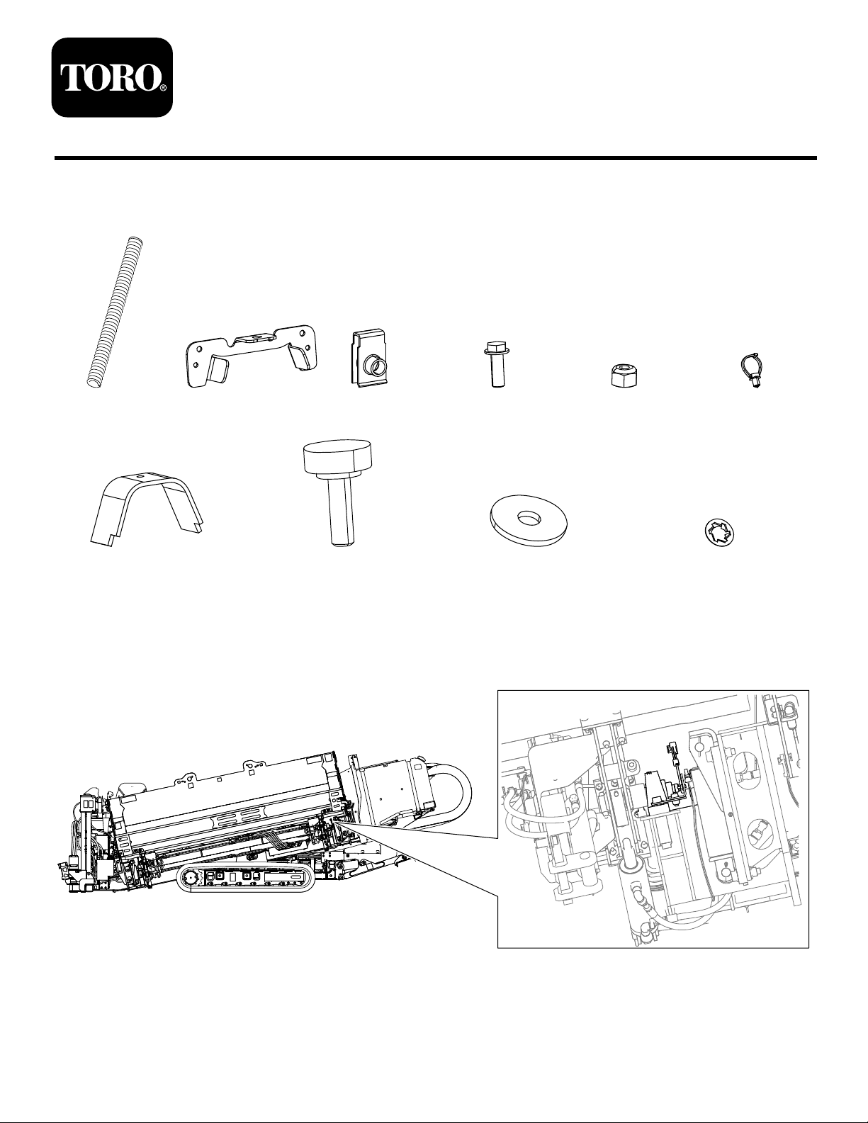
1x1x1x2x2x1x
FormNo.3424-755RevA
RotarySensorCoverKit
2024or2226DirectionalDrill
ModelNo.138-7092
InstallationInstructions
1x1x1x1x
1.Parkthemachineonalevelsurface,placethethrustframeinthehorizontalposition,shutofftheengine,
turnthebatterydisconnectswitchtotheOFFpositionandremovethekey.
2.Locatethecamassemblywhereyouwillinstallthekit(Figure1).
g260428
©2018—TheT oro®Company
8111LyndaleA venueSouth
Bloomington,MN55420
Registeratwww.T oro.com.
OriginalInstructions(EN)
PrintedintheUSA
AllRightsReserved
*3424-755*A
Page 2
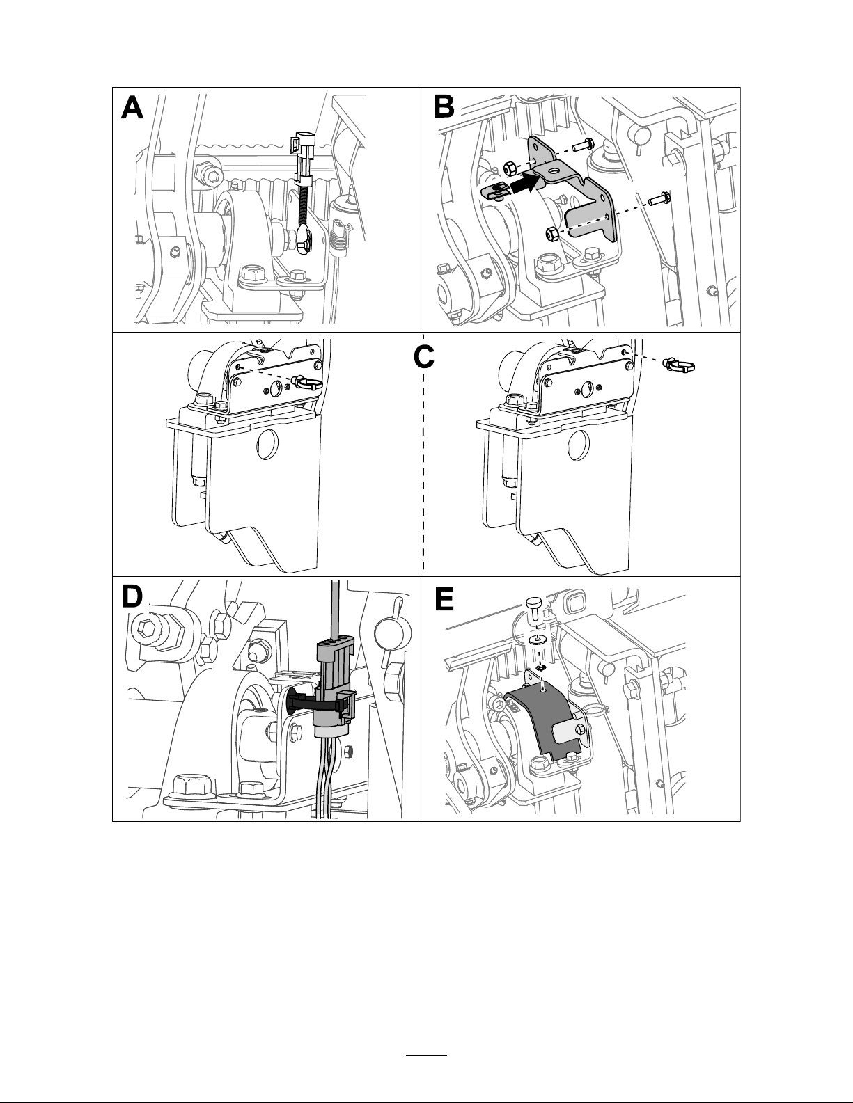
3.Disconnectthesensorwiresandremovethecabletieattachedtothebracket(BoxA).
4.Placethewireharnesscoveronthesensorwireharness(BoxA).
5.InstallthebracketontothemachineasshowninboxB.
6.Determinewhichslotonthebracketthesensorwireharnesswilltthroughwithoutstretchingtheharness.
7.Installthecabletieconnectorintotheholeclosesttothatslot(BoxC).
8.Guidethewireharnesscoverintotheslotandsecurethesensorusingthecabletie(BoxD).
9.Installandhandtightenthecoverusingthebolt,washer,andlockwasherasshowninboxE.
10.Conrmthesensorcalibration;refertoyourOperator’sManual.
2
g261455
 Loading...