

Page 1
FormNo.3421-500RevB
HeightofCutLatchingKit
Grandstand
ModelNo.138-4890
®
Mowers
InstallationInstructions
Safety
SafetyandInstructional
Decals
Safetydecalsandinstructionsare
easilyvisibletotheoperatorandare
locatednearanyareaofpotential
danger.Replaceanydecalthatis
damagedormissing.
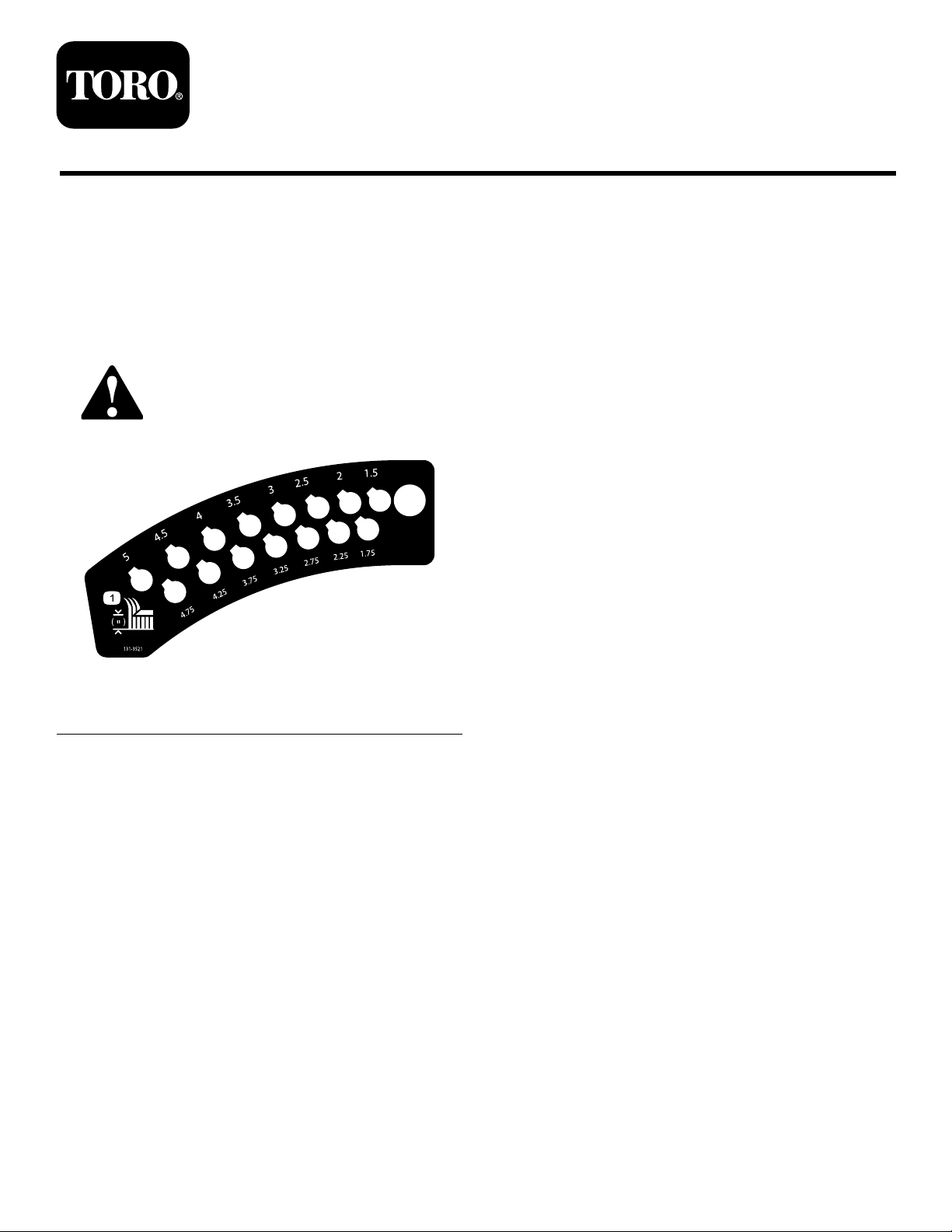
1.Heightofcut
decal131-3521
131-3521
©2018—TheToro®Company
8111LyndaleAvenueSouth
Bloomington,MN55420
Registeratwww.T oro.com.
OriginalInstructions(EN)
PrintedintheUSA
AllRightsReserved
*3421-500*B
Page 2

Installation
LooseParts
Usethechartbelowtoverifythatallpartshavebeenshipped.
ProcedureDescription
1
2
3
4
Nopartsrequired
Nopartsrequired
Latchplate1
Shoulderbolt
Washer-headshoulderbolt1
Washer2
Nut(3/8inch)
Nut(1/4inch)
Wearplug1
Spacer(1.7inches)
Spacer(2.7inches)
Innerplate1
Spacer(0.7inch)
Outerplate
Washer3
Bolt(3/8x3-3/4inches)
Nut(3/8inch)
Pin1
Qty.
Use
–
–
1
1
1
2
1
2
1
3
4
Preparethemachine.
Removetheexistingplates.
Installthelatchplate.
Installthenewplates.
1
PreparingtheMachine
NoPartsRequired
Procedure
1.Parkthemachineonalevelsurface.
2.DisengagethePTO,engagetheparkingbrake,
andmovethemotion-controlleversoutwardto
theNEUTRAL-LOCKposition.
3.Shutofftheengineandremovethekey.
2
Page 3
2
3
RemovingtheExisting Plates
NoPartsRequired
Procedure
1.Removethefueltank;refertotheOperator’s
Manualforthemachine.
2.Usetheheight-of-cutlevertolowerthemower
deckontowoodblocks.
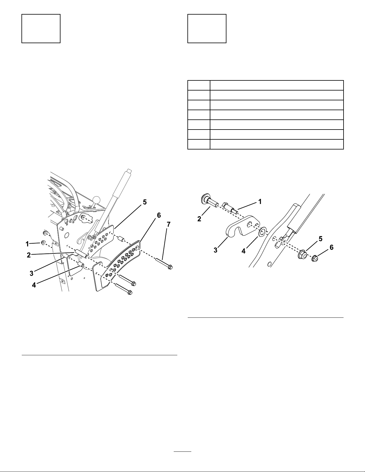
3.Removebothplatesandfastenersasshownin
Figure1.
InstallingtheLatchPlate
Partsneededforthisprocedure:
1Latchplate
1
Shoulderbolt
1Washer-headshoulderbolt
2Washer
1
Nut(3/8inch)
1
Nut(1/4inch)
1Wearplug
Procedure
1.Removethelatchfromtheheight-of-cutlever
(Figure2).
Figure1
1.Nut(3/8inch)
2.Spacer—2.6inches6.Outerplate
3.Spacer—1.4inches(2)7.Bolt—3/4x3-1/2inches
4.Spacer—1inch(2)
5.Innerplate
(3)
g246977
Figure2
1.Shoulderbolt
g246899
2.Washer-headshoulder
bolt
3.Latch
2.Cutoutthetemplateattheendofthispublication
andalignitonthelever(Figure3).
4.Washer
5.Nut(3/8inch)
6.Nut(1/4)
3
Page 4

Figure3
5.Torquetheshoulderboltto1017to1243N∙cm
(90to1 10in-lb)andtorquethewasher-head
shoulderboltto41to49N∙m(30to36ft-lb).
6.Installthewearplugintothelever(Figure4).
g255884
1.Drillthehole(3/8inch)
here.
2.Template
3.Drillahole(3/8inch)intotheleveratthelocation
showninFigure3.
4.Installthenewlatchplateusing1shoulderbolt,
1washer-headshoulderbolt,2washers,1nut
(3/8inch),1nut(1/4inch)asshowninFigure4.
Note:Ensurethatthewashersseatontothe
shoulderoftheboltandarenotpinchedbetween
theheight-of-cutliftarmandtheshoulderofthe
bolt.
Figure4
1.Shoulderbolt5.Nut(3/8inch)
2.Latch6.Wearplug
3.Latch-releaserod7.Washer
4.Nut(1/4)
8.Washer-headshoulder
bolt
g246976
4
Page 5

4
InstallingtheNewPlates
Partsneededforthisprocedure:
2
Spacer(1.7inches)
1
Spacer(2.7inches)
1Innerplate
2
Spacer(0.7inch)
1
Outerplate
3Washer
3
Bolt(3/8x3-3/4inches)
4
Nut(3/8inch)
1Pin
g247029
Figure5
Procedure
1.Installtheinnerandouterplatestothemachine
usingthespacers,washers,bolts,andnutsas
showninFigure5.
2.Installthepinintheholeforyourdesiredheight
ofcut.
1.Innerplate
2.Spacer—0.7inch(2)7.Spacer—2.7inches
3.Washer(3)8.Spacer—1.7inches(2)
4.Bolt—3/8x3-3/4inches
(3)
5.Pin
6.Outerplate
9.Nut—3/8inch(3)
5
Page 6

Notes:
Page 7

g255885
Page 8

 Loading...