

Page 1
BucketMountKit
ZMaster
ModelNo.137-9216
®
Safety
SafetyandInstructionalDecals
Safetydecalsandinstructionsareeasilyvisibletotheoperatorandarelocatednearanyarea
ofpotentialdanger.Replaceanydecalthatisdamagedormissing.
FormNo.3422-362RevA
3000,5000,or6000SeriesRidingMower
InstallationInstructions
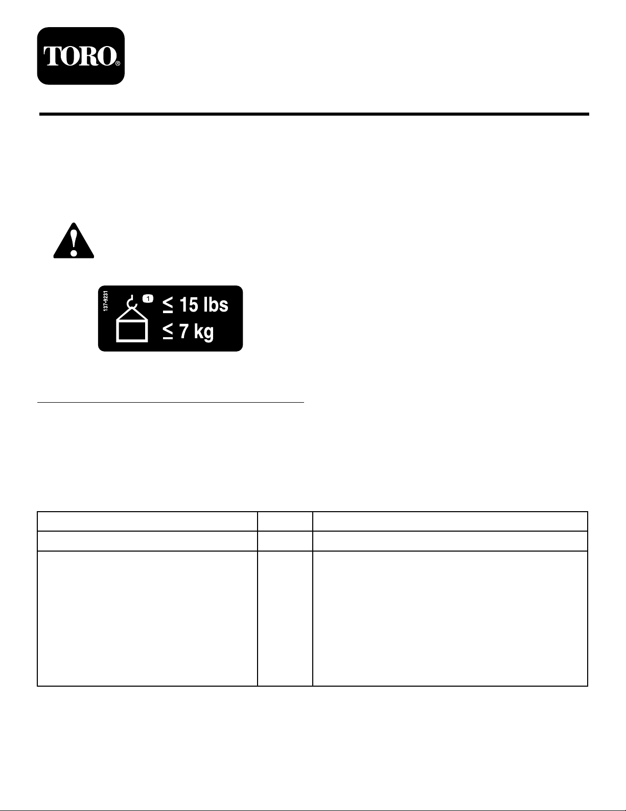
137-9231
1.Maximumweight7kg(15lb)
Installation
LooseParts
Usethechartbelowtoverifythatallpartshavebeenshipped.
Description
Nopartsrequired
Bucket-holdermount1
Bracket-supporthinge1
Mountstrap—for48,52,and60-inchdecks
Mountstrap—for72-inchdecks
Topbracket1
Knob1
Carriagebolt(5/16x7/8inch)
Flangenut(5/16inch)
Flange-headbolt(3/8x1inch)
Locknut(3/8inch)
decal137-9231
Qty.
Use
–
1
1
4
3
1
1
Preparethemachine.
Installthekit.
©2018—TheToro®Company
8111LyndaleA venueSouth
Bloomington,MN55420
Registeratwww.T oro.com.
OriginalInstructions(EN)
PrintedintheUSA
AllRightsReserved
*3422-362*A
Page 2
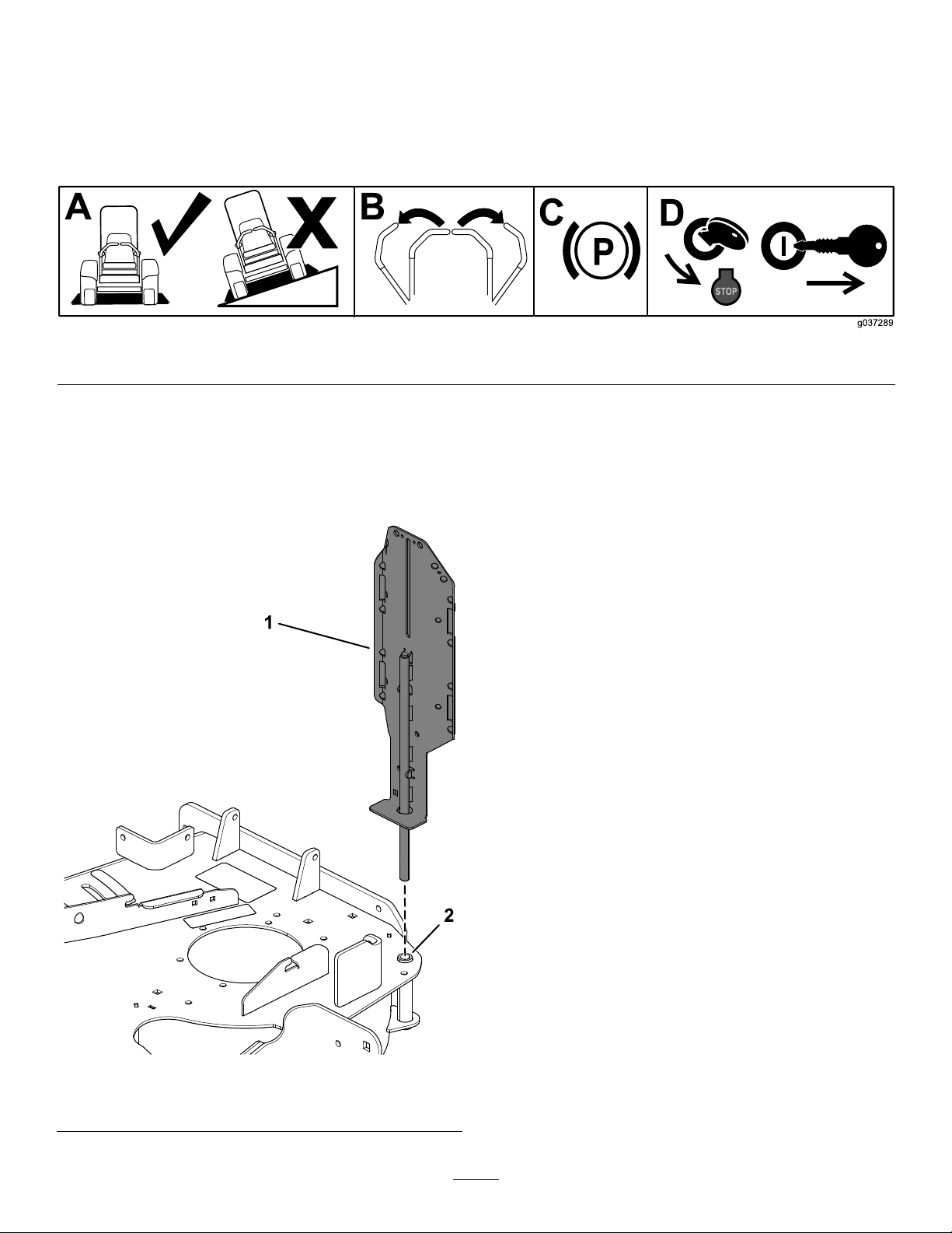
PreparingtheMachine
1.Parkthemachineonalevelsurface.
2.Movethemotion-controlleverstotheNEUTRAL-LOCKposition.
3.Engagetheparkingbrake.
4.Shutofftheengineandremovethekey .
InstallingtheKit
1.Installthebucket-holdermountintothe
deck-mountingholebythedischargeplate
(Figure2).
g037289
Figure1
Figure2
1.Bucket-holdermount2.Mountinghole
g253477
2
Page 3

2.Securethebracket-supporthingeandmount
straptothebucket-holdermountusing3
carriagebolts(5/16x7/8inch)and3angenuts
(5/16inch)asshowninFigure3.
RefertoFigure4forthepropermountstrap.
Usethemountstrapwiththe51mm(2inches)
bendoffsetand4holesfor48,52,and60-inch
decks.Usethemountstrapwiththe13mm(1/2
inch)bendoffsetand3holesfor72-inchdecks.
3.Securethemountstraptothemowerdeckusing
theange-headbolt(3/8x1inch)andlocknut
(3/8inch)asshowninFigure5.
g253480
Figure5
Figure3
1.Mountstrap4.Bracket-supporthinge
2.Flangenut(5/16inch)5.Carriagebolt(5/16x7/8
3.Bucket-holdermount
inch)
Figure4
1.Mountstrapfor48,52,
and60-inchdecks
2.Mountstrapfor72-inch
decks
1.Locknut(3/8inch)3.Flange-headbolt(3/8x1
2.Mountstrap
g253479
inch)
4.Securethetopbrackettothebucket-holder
mountusingtheknobandacarriagebolt(5/16x
7/8inch)asshowninFigure6.
g254249
Figure6
1.Knob
2.Topbracket
3.Carriagebolt(5/16x7/8
inch)
g253478
3
Page 4

Operation
MountingaBucket
UseonlyToro-approvedattachmentsandaccessories.
Themaximumcapacityis7kg(15lb).
1.Loosentheknobandraisethetopbracket.
Tightentheknobtoholditinplace(Figure7).
2.Placethebottomlipofthebucketoverthe
bottomledgeoftheweldedsupportbracket
(Figure7).
3.Loosentheknobandlowerthetopbracketasfar
aspossibleovertherimofthebucket.Tighten
theknob(Figure7).
1.Topbracketovertherimof
thebucket
2.Knob
g253491
Figure7
3.Bottomledgeofthe
supportbracket
4
 Loading...