

Page 1
Installation
LooseParts
FormNo.3414-557RevA
LiftHandleKit
MB-1600MudBuggy
ModelNo.137-0591
InstallationInstructions
WARNING
CALIFORNIA
Proposition65Warning
ThisproductcontainsachemicalorchemicalsknowntotheStateofCalifornia
tocausecancer,birthdefects,orreproductiveharm.
Usethechartbelowtoverifythatallpartshavebeenshipped.
ProcedureDescription
1
2
3
Nopartsrequired
Nopartsrequired
Pivot1
Leverplate1
Leverassembly1
Shaftguide
Pin1
Clevispin
Cotterpin(1/2inch)
Bearing2
Bolt(1/4x2-1/4inches)
Cotterpin(1inch)
Nut(1/4inch)
Qty.
Use
–
–
1
1
1
1
1
1
Preparethemachine.
Removetheexistinglifthandle.
Installthekitlifthandle.
©2017—TheT oro®Company
8111LyndaleAvenueSouth
Bloomington,MN55420
Registeratwww.T oro.com.
OriginalInstructions(EN)
PrintedintheUSA
AllRightsReserved
*3414-557*A
Page 2
1
PreparingtheMachine
NoPartsRequired
Procedure
1.Parkthemachineonalevelsurface.
2.Engagetheparkingbrake.
3.Lowerthehopper.
4.Shutofftheengine.
2
g210902
Figure1
RemovingtheExistingLift
Handle
NoPartsRequired
Procedure
1.Removethecowl.
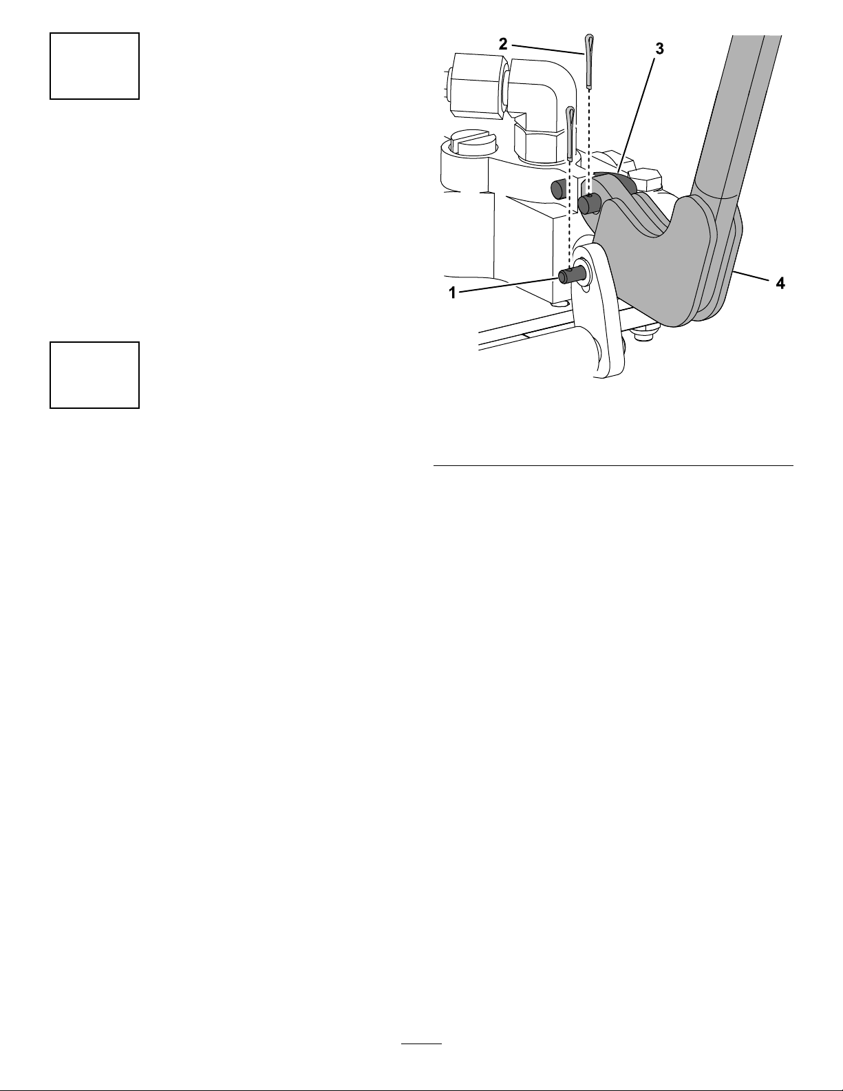
2.Removethe2cotterpins,U-link,andclevispin
(3/16x1inch)fromthehandleassembly(Figure
1).Retaintheclevispin,butdiscardthe2cotter
pinsandU-link.
1.Clevispin(3/16x1inch)
2.Cotterpin
3.Removeanddiscardthehandleassembly
(Figure1).
4.Removeandretaintheangebolt(5/16x1
inch),nut(5/16inch),clevispin(3/8x1-3/32
inch)andcotterpin(3/4inch)asshowninFigure
2.
3.U-link
4.Handleassembly
2
Page 3

Figure2
1.Flangebolt(5/16x1inch)6.Shaftguide
2.Pivot
3.Cotterpin(3/4inch)
4.Nut(5/16inch)9.Bolt(1/4x2-1/4inches)
5.Clevispin(3/8x1-3/32
inch)
7.Nut(1/4inch)
8.Leverplate
3
InstallingtheKitLiftHandle
Partsneededforthisprocedure:
1Pivot
1Leverplate
1Leverassembly
1
Shaftguide
1Pin
1
Clevispin
1
2Bearing
1
1
1
Cotterpin(1/2inch)
Bolt(1/4x2-1/4inches)
Cotterpin(1inch)
Nut(1/4inch)
g210903
Procedure
5.Removeanddiscardthebolt(1/4x2-1/4inches),
nut(1/4inch),pivot,shaftguide(includingthe2
bearings),andleverplate(Figure2).
1.Installtheshaftguideusingtheangebolt(5/16
x1inch)andnut(5/16inch)thatyouremoved
previously,andthekitbolt(1/4x2-1/4inches)
andnut(1/4inch)asshowninFigure3.
g210914
Figure3
1.Bolt(1/4x2-1/4inches)4.Nut(1/4inch)
2.Shaftguide5.Nut(5/16inch)
3.Bearing(2)6.Flangebolt(5/16x1inch)
3
Page 4

2.Installthebearingsintotheshaftguide(Figure
3).
3.Installthekitthroughtheshaftguideandhandle
assembly,andsecureitusingthecotterpin(1
inch)asshowninFigure4.
Figure4
6.Securethehandletotheleverplateusinga
cotterpin(1/2inch)andtheclevispin(3/16x1
inch)thatyouremovedpreviously(Figure6).
g210928
Figure6
1.Cotterpin(1/2inch)2.Clevispin(3/16x1inch)
7.Installthecowl.
g210926
1.Handleassembly
2.Cotterpin(1inch)
3.Clevispin
4.Slidethepivotthroughtheshaftguide,and
secureittotheyokeusingtheclevispin(3/8x
1-3/32inch)andcotterpin(3/4inch)thatyou
removedpreviously(Figure5).
Figure5
g210927
1.Pivot
2.Yoke5.Pin
3.Cotterpin(3/4inch)
4.Clevispin(3/8x1-3/32
inch)
6.Leverplate
5.Securetheotherendofthepivottothelever
plateusingapin(Figure5).
4
 Loading...