

Page 1
LightKit
MBTX2500TrackedMudBuggy
ModelNo.137-0558
WARNING
CALIFORNIA
Proposition65Warning
ThisproductcontainsachemicalorchemicalsknowntotheStateofCaliforniato
causecancer,birthdefects,orreproductiveharm.
Note:Determinetheleftandrightsidesofthemachinefromthenormaloperatingposition.
Installation
FormNo.3413-686RevA
InstallationInstructions
LooseParts
Usethechartbelowtoverifythatallpartshavebeenshipped.
ProcedureDescription
1
2
3
4
Nopartsrequired
Nopartsrequired
Bracket2
Carriagebolt(5/16x1inch)
Nut(5/16inch)
Switch
Wireharness1
Lightassembly2
Frictionwasher2
Grommet
Cabletie
Nopartsrequired
Qty.
Use
–
–
4
4
1
2
2
–
Preparethemachine.
Drilltheholes.
Installthelights.
Completetheinstallation.
©2017—TheToro®Company
8111LyndaleAvenueSouth
Bloomington,MN55420
Registeratwww.T oro.com.
OriginalInstructions(EN)
PrintedintheUSA
AllRightsReserved
*3413-686*A
Page 2
1
3
PreparingtheMachine
NoPartsRequired
Procedure
1.Parkthemachineonalevelsurface,engagetheparking
brake,andlowerthehopper.
2.Shutofftheengineandremovethekey .
3.Disconnectthenegative(-)cablefromthebattery.
4.Removethefueltank;refertotheOperator’ sManualfor
themachine.
2
DrillingtheHoles
NoPartsRequired
InstallingtheLights
Partsneededforthisprocedure:
2Bracket
4
Carriagebolt(5/16x1inch)
4
Nut(5/16inch)
1
Switch
1Wireharness
2Lightassembly
2Frictionwasher
2
Grommet
2
Cabletie
Procedure
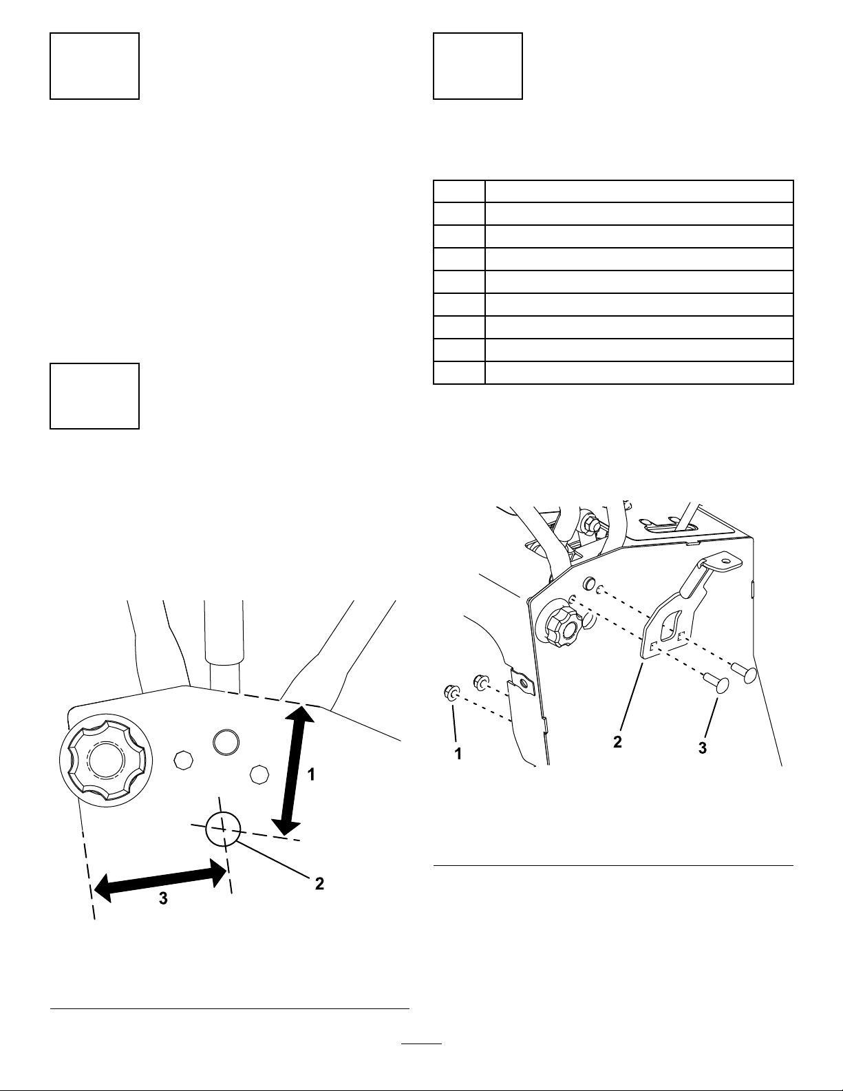
1.Onbothsidesofthemachine,installabracketusing2
carriagebolts(5/16x1inch)and2nuts(5/16inch)as
showninFigure2.
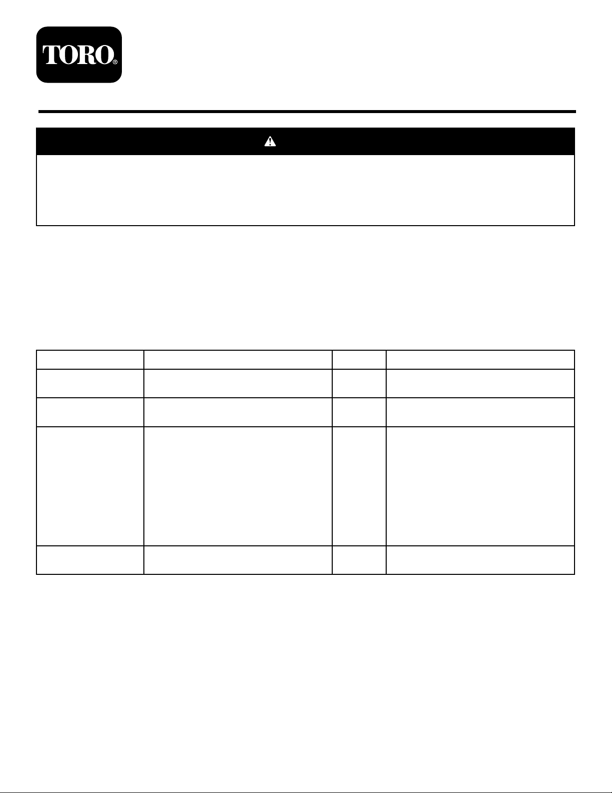
Procedure
Onbothsidesofthemachine,drillaholeintotheframe
(0.828inchdiameter)inthelocationshowninFigure1.
Figure1
g204781
Figure2
1.Nut—5/16inch(2)3.Carriagebolt—5/16x1
inch(2)
2.Bracket
g204754
1.7.4cm(2.9inches)3.7.6cm(3inches)
2.Hole(0.828inch)
2
Page 3

2.Removethebolt,lockwasher,andnutfromalight
assembly.Usethehardwareandafrictionwasher
tosecurethelighttoabracket(Figure3).Donot
overtightenthefasteners.Repeatfortheothersideof
themachine.
4.Frominsidethemachine,pushtheswitchconnector
ofthewireharnessthroughtheknockoutholeand
connectittotheswitch(Figure5).
g204812
Figure5
Figure3
1.Bolt4.Bracket
2.Light5.Lockwasher
3.Frictionwasher6.Nut
3.Removeanddiscardtheknockoutfromthetower
panel(Figure4).
Note:Theknockoutiscoveredbytheconsoledecal.
1.Switchconnectorofwire
harness
2.Switch
5.Installtheswitchintheknockouthole(Figure5).
g204816
6.Pushtherightlightconnectorthroughtheholeyou
drilledontherightsideofthemachine.Slidea
grommetovertheconnector,downthewireharness,
andsecureitinthehole(Figure6).Repeatfortheleft
wireharnessconnectorontheleftsideofthemachine.
g204815
Figure6
g204765
Figure4
1.Knockout
1.Grommet
7.Connectthelightconnectorstothelights.
3
Page 4

8.Securethewireharnesstoeachlightbracketusinga
cabletie(Figure7).
Figure7
1.Cabletie
9.Connecttheuncappedauxiliarypowerconnectorto
theauxiliarypowerconnectoronthemainwireharness
ofthemachine.
Note:Ifyouinstallanotherpoweredaccessoryto
themachine,plugitintothecappedauxiliarypower
connector.
g205225
4
CompletingtheInstallation
NoPartsRequired
Procedure
1.Installthefueltankandfuel-tankbracket;refertothe
Operator’sManualforthemachine.
2.Raisethecushion.
3.Connectthenegative(-)cabletothebattery.
4.Starttheengine.
5.Pressthelightswitchandverifythatthelightsfunction.
4
 Loading...