

Page 1

BeltCoverKit
136-9124
Riemenabdeckungen
136-9124
Kitcouvercledecourroie
FormNo.3414-414RevB
136-9124
Riemkapset
136-9124
www.T oro.com.
*3414-414*B
Page 2

Page 3

Page 4

Page 5
BeltCoverKit
AWDRecycler
ModelNo.136-9124
Installation
LooseParts
Usethechartbelowtoverifythatallpartshavebeenshipped.
FormNo.3414-400RevB
®
LawnMower
InstallationInstructions
Description
Upperbeltcover1
Lowerbeltcover1
Bolt(1/4x1.33inches)
Engine-mountbolt(3/8x1inch)
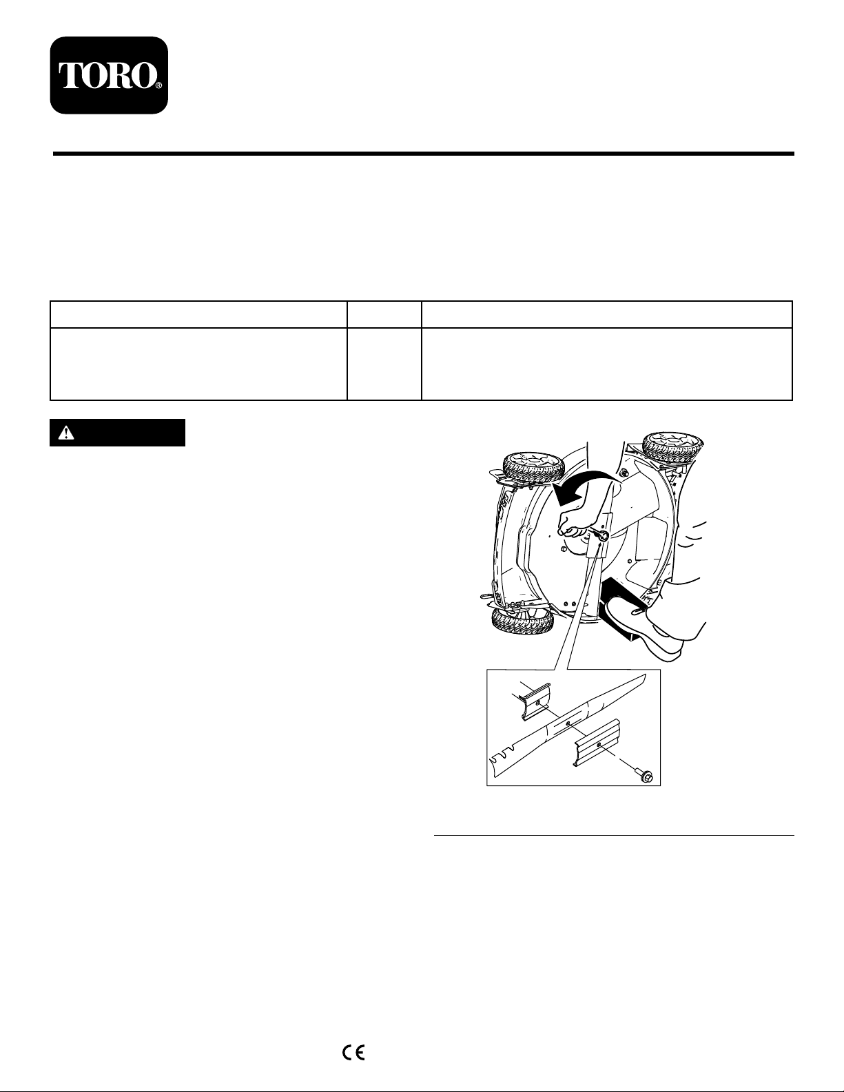
WARNING
Thebladeissharp;contactingthebladecan
resultinseriouspersonalinjury.
Weargloveswhenservicingtheblade.
PreparingtheMachine
1.Shutofftheengineandwaitforallmovingparts
tostop.
2.Disconnectthespark-plugwirefromthespark
plugandremovetheelectric-startbutton(if
present).
3.Tipthemachineontoitssidewiththeairlterup.
4.Useablockofwoodtoholdthebladesteady
(Figure1).
Qty.
Use
2
2
Installthekit.
5.Removetheblade,savingallmountinghardware
(Figure1).
©2017—TheT oro®Company
8111LyndaleAvenueSouth
Bloomington,MN55420
CV
Registeratwww.T oro.com.
Figure1
6.Loosenthe5boltsthatholdtherearbafein
place.
OriginalInstructions(EN)
PrintedintheUSA
AllRightsReserved
*3414-400*B
g206911
Page 6
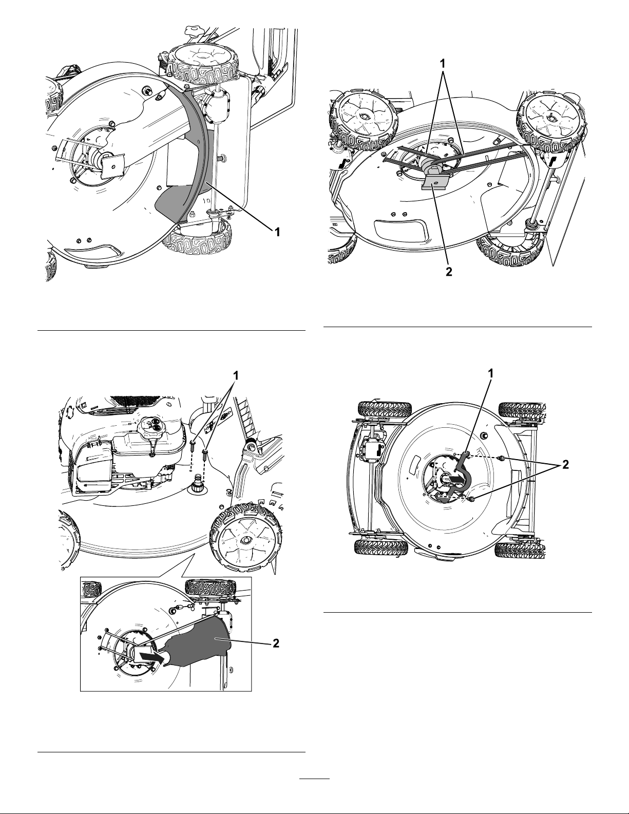
8.Removebothbeltsfromthebladedriveandthen
removeandretainthebladedrive(Figure4).
Figure2
1.Rearbafe
7.Removeandretainthelower,rearbeltcover
andcorrespondingbolts(Figure3).
g212126
1.Belts(retain)2.Bladedrive(retain)
Figure4
g211698
9.Removeanddiscardthemetalbeltguideand2
correspondingbolts(Figure5).
g212112
Figure5
1.Lower,rearbelt-cover
bolts(retain)
1.Metalbeltguide(discard)2.Belt-guidebolts(discard)
10.Removeanddiscardthefrontbeltcover;retain
thecorrespondingbolts(Figure6).
g212208
Figure3
2.Lower,rearbeltcover
(retain)
2
Page 7
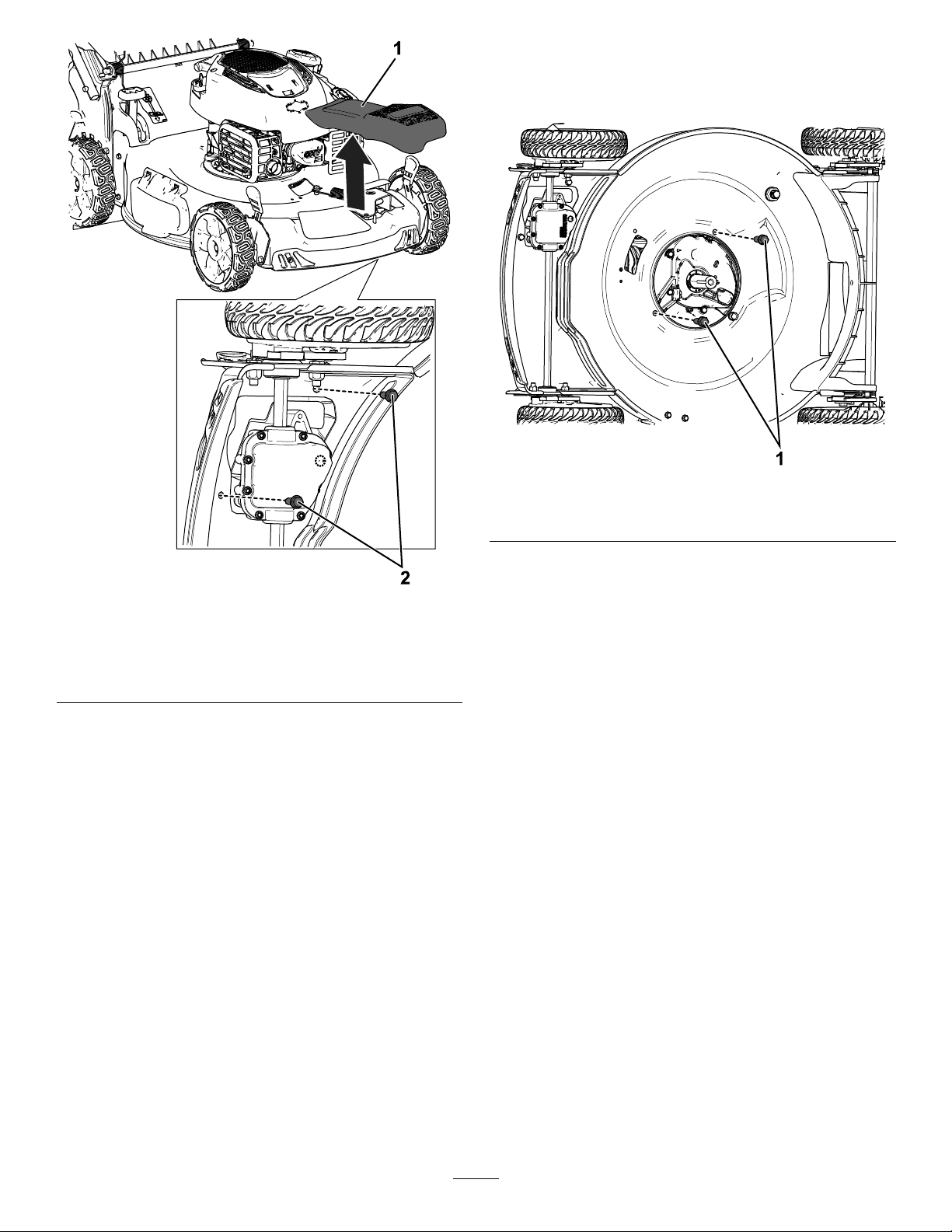
InstallingtheKit
1.Installthe2engine-mountbolts(3/8x1inch)
andtorquethemto400in-lb(Figure7).
Figure7
g212119
Figure6
Model20353shown;appearanceofmachinevaries
1.Frontbeltcover(discard)
2.Frontbelt-coverbolts
(retain)
11.Ifneeded,centerpunchandthendrill2holes
(9/32inch)throughthedeckforinstallationof
thebeltcovers.
Note:Usethetemplateatthebackofthese
instructionsfortheappropriateholeorientation.
1.Engine-mountbolts
2.Installtheupper,frontbeltcoverprovidedinthis
g212113
kitwiththeboltspreviouslyremoved.
3
Page 8
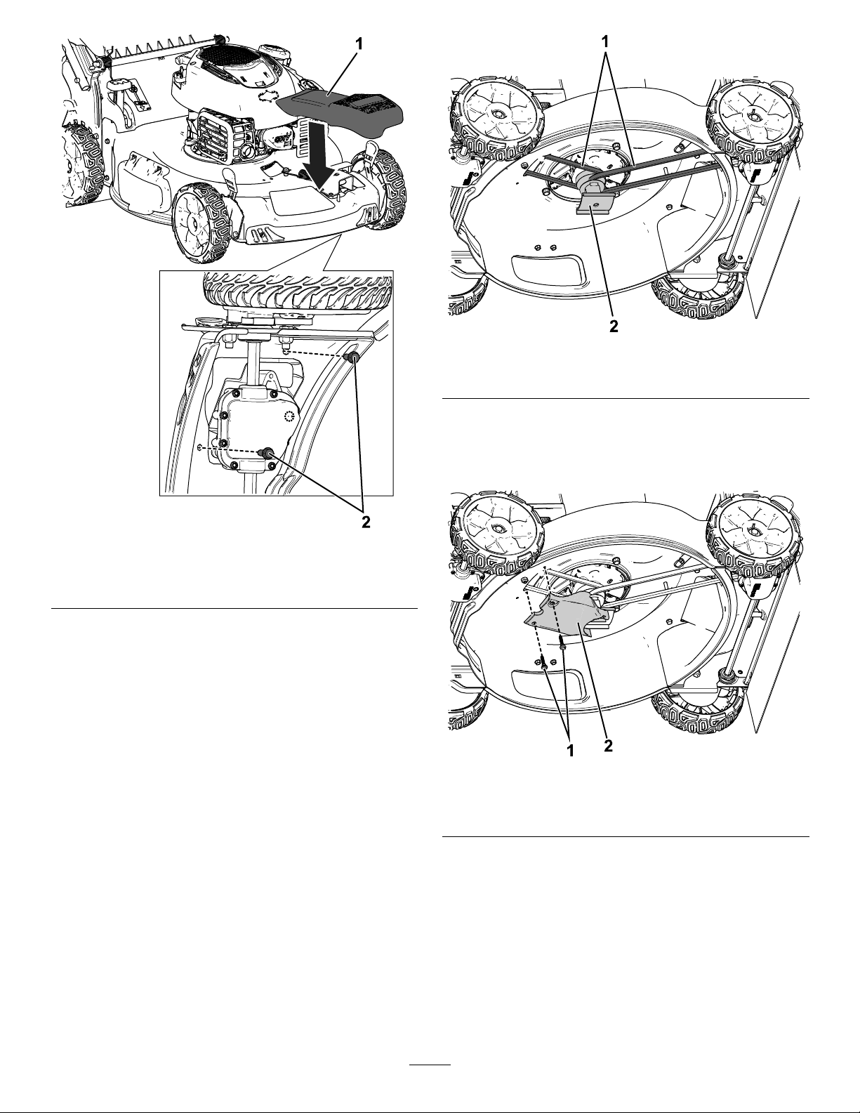
Figure8
g211698
Figure9
1.Belts2.Bladedrive
4.Installthelower,frontbeltcoverbythreading2
bolts(1/4x1.33inches)throughthelowerbelt
cover,throughtheholesdrilled(ifapplicable),
andintotheupperbeltcover.
g212120
1.Upper,frontbeltcover2.Upper,frontbelt-cover
bolts
3.Installthebladedriveandroutebothbelts
arounditasshowninFigure8.
Note:Thebladespacerneedtoremaininside
ofthebladedrive.
g212121
Figure10
1.Lower,frontbeltcover2.Lower,frontbelt-cover
bolts
5.Tightenthe5boltsthatholdtherearbafein
place(Figure10).
4
Page 9
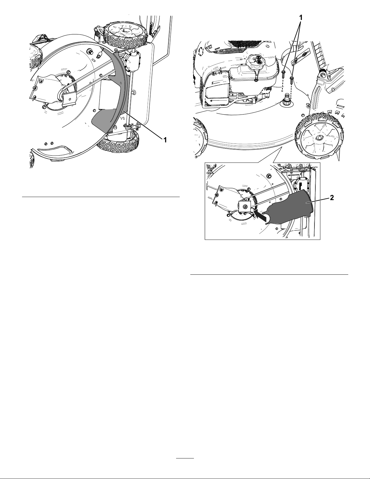
Figure11
1.Rearbafe
6.Installthelower,rearbeltcoverwiththe
correspondingboltsthatyoupreviously
removed.Insertthebackofthecoverintothe
reardischargechuteandthenlowerthefrontin
place(Figure12).
Note:Ensurethattherearbeltdoesnotget
pinchedbetweenthesidewallandboltswhen
installingthelower,rearbeltcover.
g212127
g212123
Figure12
1.Lower,rearbelt-cover
bolts
2.Lower,rearbeltcover
5
Page 10
InstallingtheBlade
Important:Y ouwillneedatorquewrenchto
installthebladeproperly.Ifyoudonothavea
torquewrenchorareuncomfortableperforming
thisprocedure,contactanAuthorizedService
Dealer.
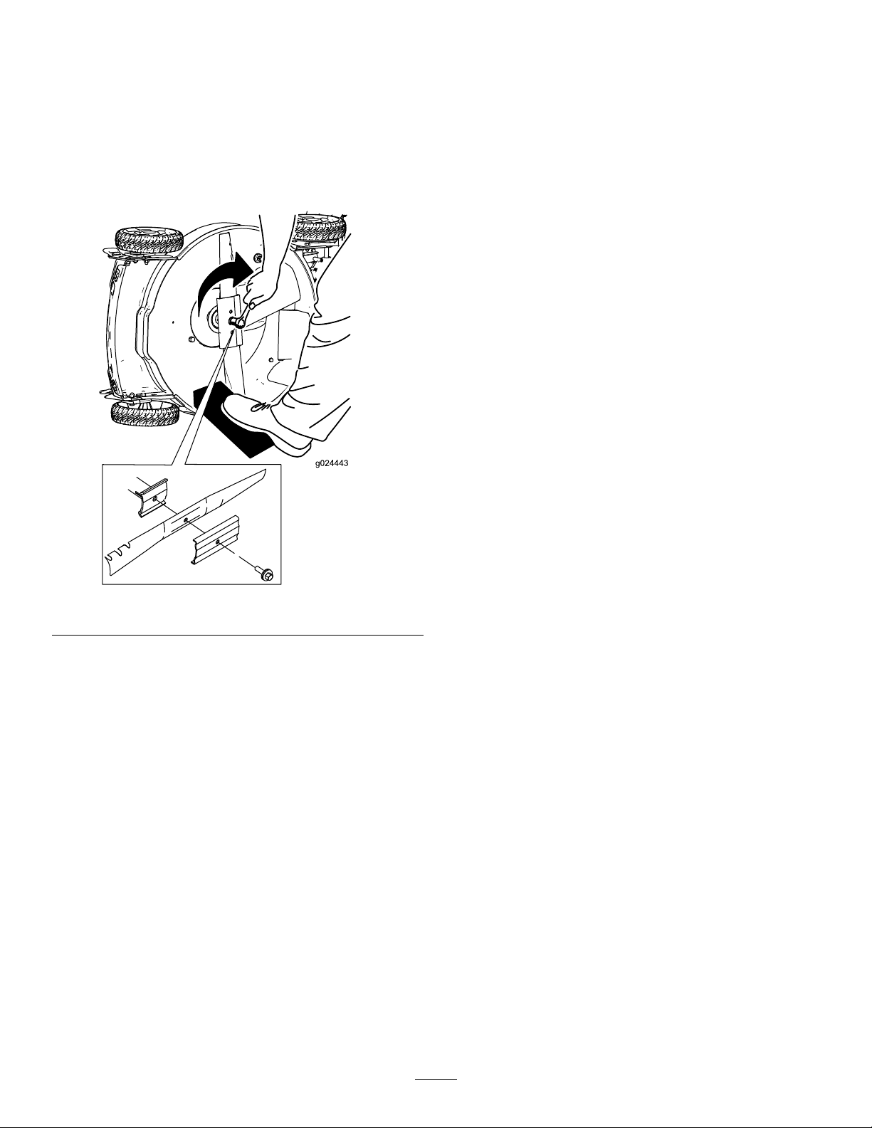
1.Installthenewbladeandallmountinghardware
(Figure13).
Figure13
Important:Positionthecurvedendsofthe
bladetopointtowardthemachinehousing.
2.Useatorquewrenchtotightenthebladeboltto
82N∙m(60ft-lb).
Important:Abolttorquedto82N∙m(60
ft-lb)isverytight.Whileholdingtheblade
withablockofwood,putyourweight
behindtheratchetorwrenchandtightenthe
boltsecurely.Thisboltisverydifcultto
overtighten.
g024443
6
Page 11
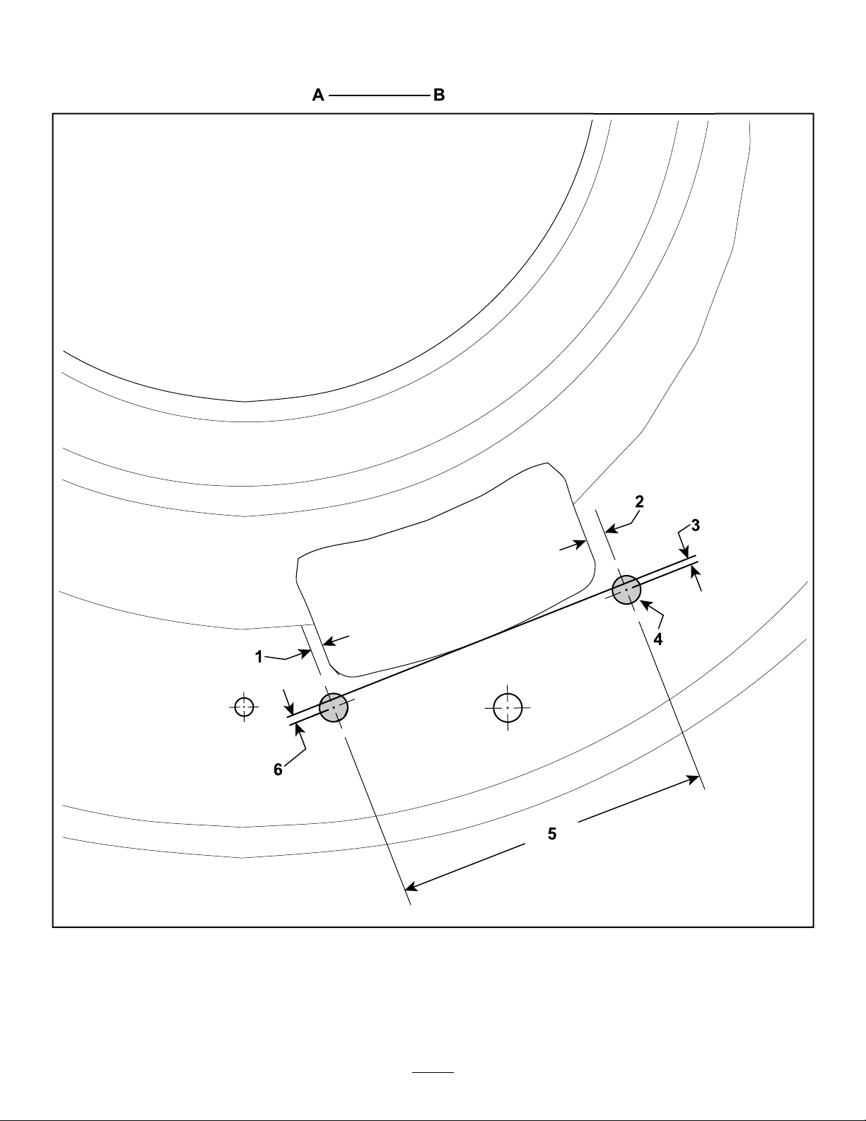
Template
Important:Ifyouareprintingthisfromwww.Toro.com,ensurethatitisprintedat100%scaleandthat
thedistancefromAtoBis1inch:.
1.3.1mm(0.12inch)3.1.5mm(0.06inch)5.79mm(3.11inches)
2.4.8mm(0.19inch)4.7.1mm(0.28inch)diameter6.2.3mm(0.09inch)
7
g206972
Page 12

Page 13

FormNo.3414-403RevB
Riemenabdeckungen
Recycler
Modellnr.136-9124
®
RasenmähermitAllradantrieb
Installationsanweisungen
Installation
Einzelteile
PrüfenSieanhanddernachstehendenTabelle,dassSiealleimLieferumfangenthaltenenT eileerhaltenhaben.
BeschreibungMengeVerwendung
ObereRiemenabdeckung
UntereRiemenabdeckung1
Schraube(¼"x1,33")
Motorbefestigungsschraube(⅜"x1")
1
2
2
DasKiteinbauen.
WARNUNG:
DasMesseristscharf;einKontaktkannzu
schwerenVerletzungenführen.
TragenSieHandschuhe,wennSiedasMesser
warten.
VorbereitenderMaschine
1.StellenSiedenMotorabundwartenSie,bis
allebeweglichenT eilezumStillstandgekommen
sind.
2.SchließenSiedenZündkerzenstecker
vonderZündkerzeabundziehenSiedie
Elektrostarttasteab(fallsvorhanden).
3.KippenSiedieMaschineaufdieSeite,sodass
derLuftlternachobenzeigt.
4.StabilisierenSiedasMessermiteinem
Holzblock(Bild1).
5.NehmenSiedasMesserabundbewahrenSie
alleBefestigungsschraubenauf(Bild1).
g206911
Bild1
©2017—TheT oro®Company
8111LyndaleAvenueSouth
Bloomington,MN55420
CV
RegistrierenSieIhrProduktunter
www.T oro.com.
6.LösenSiediefünfSchrauben,mitdenendas
HinteresAblenkblechbefestigtist.
Originaldokuments(DE)
AlleRechtevorbehalten
Druck:USA
*3414-403*B
Page 14

g212126
Bild2
1.HinteresAblenkblech
7.EntfernenundbewahrenSiedieuntere
Riemenabdeckunghintenunddie
entsprechendenSchraubenauf(Bild
3).
1.UntereSchrauben
anhinterer
Riemenabdeckung
(aufbewahren).
8.NehmenSiebeideRiemenvomMesserantrieb
abundentfernenSiedanndenMesserantrieb;
bewahrenSieihnauf(Bild4).
g212208
Bild3
2.Unterehintere
Riemenabdeckung
(aufbewahren).
g211698
Bild4
1.Riemen(aufbewahren)
2.Messerantrieb
(aufbewahren)
2
Page 15

9.EntfernenSiedieMetallriemenführungunddie
zweientsprechendenSchraubenundwerfensie
weg(Bild5).
Bild5
g212112
1.Metallriemenführung
(wegwerfen)
2.Riemenführungsschrauben
10.EntfernenSiedievordereRiemenabdeckung
undwerfensieweg;bewahrenSiedie
entsprechendenSchraubenauf(Bild6).
(wegwerfen)
g212113
Bild6
BildzeigtModell20353;Maschinensehenunterschiedlich
aus
1.VordereRiemenabdeckung(wegwerfen)
2.Schraubenfürvordere
Riemenabdeckung
(aufbewahren).
11.StanzenSieggf.undbohrenSiedannzwei
Löcher(9/32")durchdasMähwerk,umdie
Riemenabdeckungenzubefestigen.
Hinweis:VerwendenSiedieSchabloneauf
derRückseitedieserAnweisungenfürdie
richtigeLochausrichtung.
3
Page 16

EinbauendesKits
1.SetzenSiediezweiMotorbefestigungsschrauben(⅜"x1")einundziehensiemit45,2N·m
an(Bild7).
Bild7
g212119
1.Motorbefestigungsschrauben
2.BefestigenSiedieobere,vordere
RiemenabdeckungausdemKitmitden
vorherentferntenSchrauben.
Bild8
1.Obere,vordere
Riemenabdeckung
2.Schraubenfür
obere,vordere
Riemenabdeckung
3.MontierenSiedenMessermitnehmerund
verlegenSiebeideRiemenumihn,wieinBild
8abgebildet.
Hinweis:DasMesserdistanzstückmussan
derInnenseitedesMessermitnehmersbleiben.
g212120
4
Page 17

Bild9
1.Riemen2.Messermitnehmer
4.SchraubenSiezumMontierenderunteren
RiemenabdeckungvornezweiSchrauben(¼"
x1,33")durchdieuntereRiemenabdeckung,
durchdieBohrlöcher(fallsvorhanden)undin
dieobereRiemenabdeckung.
g211698
g212127
Bild11
1.HinteresAblenkblech
6.BefestigenSiedieuntereRiemenabdeckung
hintenmitdenvorherentferntenentsprechenden
Schrauben.SetzenSiedieRückseiteder
AbdeckungindenhinterenAuswurfkanalein
undsenkenSiedanndieVorderseiteab(Bild
12).
Hinweis:StellenSiesicher,dassderhintere
RiemennichtzwischenderSeitenwandund
denSchraubeneingeklemmtist,wennSiedie
untere,hintereRiemenabdeckungbefestigen.
Bild10
1.Untere,vordere
Riemenabdeckung
2.Schraubenfür
untere,vordere
Riemenabdeckung
5.ZiehenSiediefünfSchraubenan,mitdenen
dashintereAblenkblechbefestigtist(Bild10).
g212121
5
Page 18

Bild13
Wichtig:DasgebogeneEndedesMessers
solltezumMähwerkgehäusezeigen.
2.ZiehenSiedieMesserschraubemiteinem
Drehmomentschlüsselmit81N·man.
g024443
Bild12
1.Schraubenfüruntere,
hintereRiemenabdeckung
2.Untere,hintere
Riemenabdeckung
MontierendesMessers
Wichtig:SiebenötigenfürdenrichtigenEinbau
desMesserseinenDrehmomentschlüssel.Wenn
SiekeinenDrehmomentschlüsselhabenoder
dieseArbeitnichtausführenmöchten,wenden
SiesichaneinenofziellenVertragshändler.
1.SetzenSiedasneueMesserundalleSchrauben
auf(Bild13).
g212123
Wichtig:Einemit81N·mangezogene
Schraubesitztsehrfest.ArretierenSie
dasMessermiteinemHolzstückund
verlagernSiegleichzeitigdasGewichtauf
denSchlüsselundziehenSiedieSchraube
fest.DieseSchraubekannfastnichtzufest
angezogenwerden.
6
Page 19

Schablone
Wichtig:WennSiediesvonwww.T oro.comausdrucken,stellenSiesicher,dassSieesimMaßstabvon
100%ausdruckenunddassderAbstandvonAbisB2,5cmbeträgt:.
1.3,1mm3.1,5mm5.79mm
2.4,8mm4.7,1mm,Durchmesser6.2,3mm
7
g206972
Page 20

Page 21

Kitcouvercledecourroie
TondeuseRecycler
N°demodèle136-9124
®
àtractionintégrale
Montage
Piècesdétachées
Reportez-vousautableauci-dessouspourvériersitouteslespiècesontétéexpédiées.
FormNo.3414-406RevB
Instructionsdemontage
Description
Couvercledecourroiesupérieur
Couvercledecourroieinférieur
Boulon(¼"x1,33")
Boulondexationdumoteur(3/8"x1")
ATTENTION
Lalameesttranchanteetvouspouvezvous
blessergravementàsoncontact.
Portezdesgantspoureffectuerl'entretiende
lalame.
Préparationdelamachine
1.Coupezlemoteuretattendezl'arrêtcompletde
touteslespiècesmobiles.
2.Débranchezleldelabougieetretirezlebouton
dedémarrageélectrique(lecaséchéant).
3.Basculezlamachinesurlecôté(ltreàairen
haut).
Qté
1
1
2
2
Montagedukit.
Utilisation
4.Immobilisezlalameavecunmorceaudebois
(Figure1).
5.Déposezlalamemaisnejetezpaslesxations
(Figure1).
©2017—TheToro®Company
8111LyndaleAvenueSouth
Bloomington,MN55420
CV
Enregistrezvotreproduitàwww.Toro.com.
Figure1
6.Desserrezles5boulonsquixentledéecteur
arrièreenplace.
Traductiondutexted'origine(FR)
ImpriméauxÉtats-Unis
Tousdroitsréservés
g206911
*3414-406*B
Page 22

1.Déecteurarrière
g212126
Figure2
7.Retirezetconservezlecouvercledecourroie
inférieurarrièreainsiquelesboulons
correspondants(Figure3).
Figure3
1.Boulonsdecouverclede
courroieinférieurarrière
(conserver)
2.Couvercledecourroie
inférieurarrière
(conserver)
8.Retirezlesdeuxboulonsdel'entraînementdela
lame,puisdéposezetconservezl'entraînement
(Figure4).
g212208
g211698
Figure4
1.Courroies(conserver)
2.Entraînementdelalame
(conserver)
2
Page 23

9.Retirezetmettezaurebutleguide-courroieen
métalainsiqueles2boulonscorrespondants
(Figure5).
Figure5
g212112
1.Guidedecourroieen
métal(mettreaurebut)
10.Retirezetmettezaurebutlecouvercle
decourroieavant;conservezlesboulons
correspondants(Figure6).
2.Boulonsdeguidede
courroie(mettreaurebut)
Figure6
Modèle20353montré;l'aspectdelamachinepeutvarier
1.Couvercledecourroie
avant(mettreaurebut)
2.Boulonsdecouverclede
courroieavant(conserver)
11.Aubesoin,marquezaupointeauetpercez2
trous(9/32")dansleplateaupourmonterles
couverclesdecourroie.
Remarque:Utilisezlegabaritaudosdeces
instructionspourorientercorrectementlestrous.
g212113
3
Page 24

Montagedukit
1.Montezles2boulonsdexationdumoteur
(3/8"x1")etserrez-lesà45N·m(Figure7).
Figure7
g212119
1.Boulondexationdumoteur
2.Fixezlecouvercledecourroiesupérieuravant
comprisdanscekitaumoyendesboulons
retirésprécédemment.
Figure8
1.Couvercledecourroie
supérieuravant
2.Boulonsdecouverclede
courroiesupérieuravant
3.Montezlesystèmed'entraînementdelalameet
acheminezlesdeuxcourroiesautour,comme
montréàlaFigure8.
Remarque:L'entretoisedelelamedoitrester
àl'intérieurdusystèmed'entraînement.
g212120
4
Page 25

Figure9
g211698
1.Courroies2.Systèmed'entraînement
delalame
4.Montezlecouvercleinférieurdecourroieavant
eninsérant2boulons(¼"x1,33")dansles
trousducouvercle,puisenvissantlesboulons
danslestrouspercés(lecaséchéant)etdans
lecouvercledecourroiesupérieur.
g212127
Figure11
1.Déecteurarrière
6.Fixezlecouvercleinférieurdecourroiearrière
aveclesboulonscorrespondantsretirés
précédemment.Insérezl'arrièreducouvercle
danslagoulotted'éjectionarrièrepuisabaissez
l'avantenplace(Figure12).
Remarque:Vériezquelacourroiearrière
n'estpaspincéeentrelaparoilatéraleetles
boulonsquandvousinstallezlecouvercle
inférieurarrière.
Figure10
1.Couvercledecourroie
inférieuravant
5.Serrezles5boulonsquixentledéecteur
arrièreenplace(Figure10).
g212121
2.Boulonsdecouverclede
courroieinférieuravant
5
Page 26

Figure13
Important:Lesextrémitésrelevéesdela
lamedoiventêtredirigéesverslatondeuse.
2.Àl'aided'uneclédynamométrique,serrezle
boulondelalameà82N·m.
g024443
Figure12
1.Boulonsdecouverclede
courroieinférieurarrière
2.Couvercledecourroie
inférieurarrière
Posedelalame
Important:Vousaurezbesoind'uneclé
dynamométriquepourmonterlalame
correctement.Sivousn'enpossédezpas
ousivousnevoussentezpascapable
d'effectuercetteprocédure,adressez-vousàun
concessionnaire-réparateuragréé.
1.Montezlanouvellelameettouteslesxations
(Figure13).
g212123
Important:Unboulonvisséà82N·m
esttrèsserré.Bloquezlalameavecune
caleenbois,appuyezdetoutvotrepoids
surlerochetoulaclé,etserrezleboulon
solidement.Ilestpratiquementimpossible
detropserrerceboulon.
6
Page 27

Gabarit
Important:Sivousimprimezceciàpartirdewww.Toro.com,utilisezl'échellede100%pourquela
distancedeAàBsoitégaleà25,4mm:.
1.3,1mm3.1,5mm5.79mm
2.4,8mm4.7,1mm6.2,3mm
7
g206972
Page 28

Page 29

Riemkapset
Recycler
Modelnr.:136-9124
®
grasmaaiermetvierwielaandrijving
Installatie
Losseonderdelen
Gebruikonderstaandelijstomtecontrolerenofalleonderdelenzijngeleverd.
FormNo.3414-409RevB
Installatie-instructies
Omschrijving
Bovensteriemkap1
Ondersteriemkap
Bout(¼"x1,33")
Motorbevestigingsbout(⅜"x1")
WAARSCHUWING
Hetmaaimesisscherp,contactmethet
maaimeskanernstiglichamelijkletsel
veroorzaken.
Gebruikhandschoenenalsuhetmes
monteert.
Demachinevoorbereiden
1.Zetdemotoruitenwachttotdatallebewegende
onderdelentotstilstandgekomenzijn.
2.Trekdebougiekabellosvandebougieen
verwijderdeelektrischestartknop(indien
aanwezig).
Hoeveel-
heid
1
2
2
Desetmonteren.
Gebruik
3.Kanteldemaaimachineopzijnzijmethet
luchtlternaarboven.
4.Gebruikeenblokhoutomhetmesstiltehouden
(Figuur1).
5.Verwijderhetmesenbewaaralle
bevestigingselementen(Figuur1).
©2017—TheT oro®Company
8111LyndaleAvenueSouth
Bloomington,MN55420
CV
Registreeruwproductopwww.Toro.com.
Figuur1
6.Maakde5boutenloswaarmeehetachterste
schotisbevestigd.
Vertalingvandeoorspronkelijketekst(NL)
GedruktindeVS
Allerechtenvoorbehouden
g206911
*3414-409*B
Page 30

1.Achtersteschot
g212126
Figuur2
7.Verwijderdeondersteriemkapachteralsookde
bijbehorendebouten;bewaardezeonderdelen
(Figuur3).
Figuur3
1.Boutenvandeonderste
riemkapachter(bewaren)
2.Ondersteriemkapachter
8.Neembeideriemenvandemesaandrijving,
verwijderdeaandrijvingdanenbewaardeze
(Figuur4).
g212208
(bewaren)
Figuur4
1.Riemen(bewaren)2.Mesaandrijving(bewaren)
2
g211698
Page 31

9.Verwijderdemetalenriemgeleiderende2
bijbehorendebouten;gooidezeonderdelenweg
(Figuur5).
Figuur5
g212112
1.Metalenriemgeleider
(weggooien)
2.Riemgeleider-bouten
(weggooien)
10.Verwijderdevoorsteriemkapengooidezeweg;
bewaardebijbehorendebouten(Figuur6).
Figuur6
Model20353afgebeeld;uwmachinekanerandersuitzien
1.Voorsteriemkap
(weggooien)
2.Boutenvandevoorste
riemkap(bewaren)
11.Indiennodig:boortweegatenvan7,5mm
doorhetdekomderiemkappentemonteren.
Markeerdegateneerstmeteencenterpons.
Opmerking:Gebruikhetsjabloonopheteind
vandezeinstructiesomnategaanwaarde
gatenzichmoetenbevinden.
g212113
3
Page 32

Desetmonteren
1.Monteerde2motorbevestigingsbouten(⅜"x1")
endraaizevastmet45,2N·m(Figuur7).
Figuur7
g212119
1.Motorsbevestigingsbouten
2.Monteerdebijgeleverdebovensteriemkapmet
deboutendieueerderverwijderdhebt.
g212120
Figuur8
1.Bovensteriemkapvoor2.Boutenvandebovenste
riemkapvoor
3.Monteerdemesaandrijvingenleiddebeide
riemeneromheenzoalsafgebeeldinFiguur8.
Opmerking:Laathetmesafstandsstukinde
mesaandrijvingzitten.
4
Page 33

Figuur9
1.Riemen2.Mesaandrijving
4.Monteerdeondersteriemkapvoordoor2
bouten(¼"x1,33inch)aantebrengendoorde
ondersteriemkap,doordeboorgaten(indien
vantoepassing)enindebovensteriemkap.
g211698
g212127
Figuur11
1.Achtersteschot
6.Monteerdeondersteriemkapachtermetde
bijbehorendeboutendieueerderverwijderd
hebt.Brengdeachterzijdevandekapaanin
hetachteruitworpkanaalenlaatvervolgensde
voorzijdeopzijnplaatszakken(Figuur12).
Opmerking:Zorgdatdeachtersteriemniet
bekneldraakttussendezijwandendebouten
bijhetmonterenvandeondersteriemkapachter
monteert.
Figuur10
1.Ondersteriemkapvoor
2.Boutenvandeonderste
riemkapvoor
5.Draaide5boutenvanhetachtersteschotvast
(Figuur10).
g212121
5
Page 34

Figuur13
Belangrijk:Degebogenuiteindenvanhet
mesmoetennaardemachinewijzen.
2.Gebruikeenmomentsleutelomdemesboutvast
tedraaienmet82N·m.
g024443
Figuur12
1.Boutenvandeonderste
riemkapachter
2.Ondersteriemkapachter
Hetmaaimesmonteren
Belangrijk:Uhebteenmomentsleutelnodigom
hetmesopcorrectewijzetemonteren.Alsugeen
momentsleutelhebtofnietgoedweethoeude
montagemoetuitvoeren,kuntucontactopnemen
meteenerkendeservicedealer.
1.Monteerhetnieuwemesenalle
bevestigingselementen(Figuur13).
g212123
Belangrijk:Eenboutdieisaangetrokken
tot82N·mzitergvast.Zethetmesvastmet
eenstukhoutenplaatsuwvollegewicht
achterde(dop)sleutelomdeboutgoedvast
tedraaien.Hetisergmoeilijkomdezebout
tevasttedraaien.
6
Page 35

Template
Belangrijk:Alsudezeafdrukmaaktvanafwww.T oro.com,zorgdandatdeafdrukeenschaalvan100%
heeftendatdeafstandtussenAenB1"=25,4mmbedraagt:.
1.3,1mm3.1,5mm5.79mm
2.4,8mm4.Diametervan7,1mm6.2,3mm
7
g206972
Page 36

 Loading...