

Page 1

Installation
LooseParts
FormNo.3406-164RevB
LoaderArmWearStripKit
TX1000CompactToolCarrier
ModelNo.133-0241
InstallationInstructions
WARNING
CALIFORNIA
Proposition65Warning
ThisproductcontainsachemicalorchemicalsknowntotheStateofCaliforniato
causecancer,birthdefects,orreproductiveharm.
Usethechartbelowtoverifythatallpartshavebeenshipped.
ProcedureDescription
Lefttemplate
1
2
3
Righttemplate1
Guide
Hex-socketbolt2
Leftwearpad
Rightwearpad1
Bolt(1/4x3/8inch)
Bolt(1/4x5/8inch)
Washer2
Locknut2
Thread-lockingcompound1
Nopartsrequired
Qty.
10
Use
1
2
1
6
–
Preparethemachine.
Installthekit.
Completetheinstallation.
©2016—TheT oro®Company
8111LyndaleAvenueSouth
Bloomington,MN55420
Registeratwww.T oro.com.
OriginalInstructions(EN)
PrintedintheUSA
AllRightsReserved
*3406-164*B
Page 2
1
PreparingtheMachine
Partsneededforthisprocedure:
1
Lefttemplate
1Righttemplate
PreparingtheLoaderArms
1.Parkthemachineonalevelsurface,lowertheloader
arms,settheparkingbrake,shutofftheengine,and
removethekeyfromtheignitionswitch.
2.Removeanyattachmentsonthemachine.
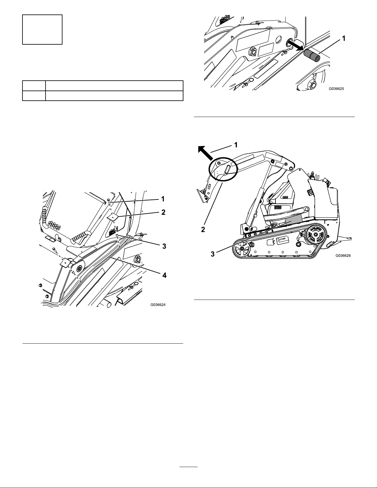
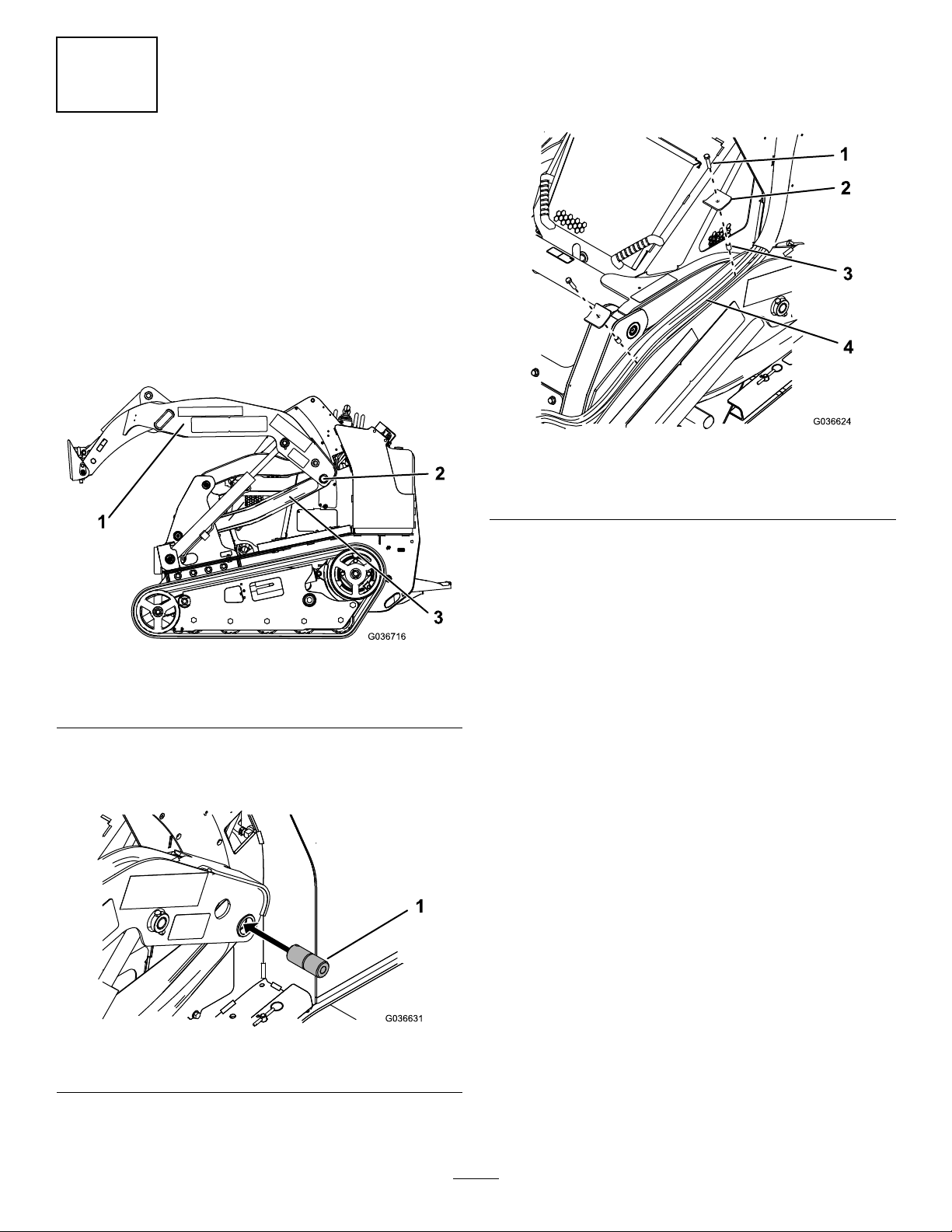
3.Removeandretainthespacers,hoseplates,andbolts
thatsecurethehydraulichosestotheloaderarms
(Figure1).
Figure2
1.Pin
6.AttachahoisttothelocationshowninFigure3and
carefullylifttheloaderarmassemblyupandforward.
Figure1
1.Bolt
2.Hoseplate4.Hoses
4.Movethehosesofftheloaderarms.
5.Removethenutandboltsecuringthepinsintheleft
andrightlowerlinksontheloaderarmassemblyand
removethepins(Figure2).
Note:Thelowerlinkscanmoveupwiththeloader
armassemblywhenraisedwithoutthepins.Placea
woodblockbetweentheframeandlowerlinkbefore
liftingthearmsorpreparetocapturethelowerlink
beforeitfalls(Figure3).Donotuseyourhandsto
supportorcatchthelowerlinkonceitisfreefromthe
assembly.
3.Spacer
Figure3
1.Lifttheloaderarm
assemblythisdirection.
2.Attachthehoisthere.
7.Oncethelowerlinksarefreefromtheassembly ,liftthe
loaderarmsuntiltheyarepasttheframe.
3.Woodblock
2
Page 3
DrillingtheHoles
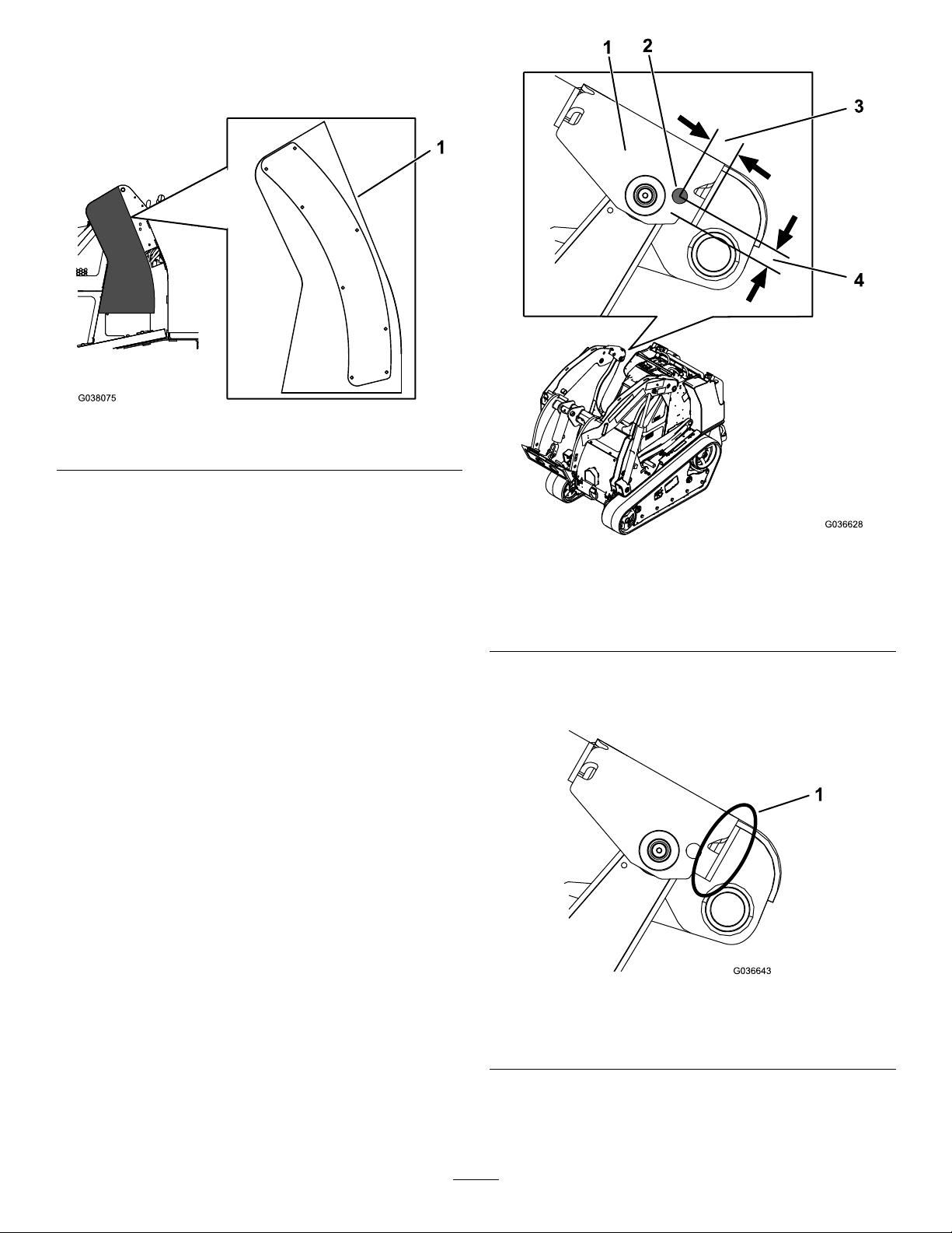
1.Tapethetemplatestocorrespondingsidesofthe
machine(Figure4).
Figure4
1.Lefttemplateandwearpad
2.Alignthewearpadstothetemplateandmarkthewear
padholesontothetemplate.
3.Drillholes(13/64-inchdiameter)atthelocations
thatyoumarked.Tapthreadsintheholes(1/4-inch
diameter,20threadsperinch).
Note:Theholesonthetemplateexistonlyasa
reference.
4.Drillahole(11/16-inchdiameter)intheconnectarm
plateoftheleftandrightloaderarmsatthelocation
showninFigure5.
Note:Youmayneedtodrillmultipletimestoachieve
thedesiredholesize.
Figure5
Insideofrightarmshown
1.Connect-armplate3.2.5cm(1inch)
2.Drillhere.
4.2.1cm(0.83inch)
5.Ifnecessary,grindtheedgeoftheconnect-armplateat
thelocationshowninFigure6toincreasetheclearance
betweenthemachineframeandloaderarm.
Figure6
Rightarmshown
1.Grindthisedge.
6.Cleanallmetalshavingsfromthemachineandpaint
exposedmetal.
3
Page 4

2
InstallingtheKit
Partsneededforthisprocedure:
2
Guide
2Hex-socketbolt
1
Leftwearpad
1Rightwearpad
6
Bolt(1/4x3/8inch)
10
Bolt(1/4x5/8inch)
2Washer
2Locknut
1Thread-lockingcompound
Procedure
1.Installahex-socketbolt,guide,washer,andlocknutin
eachholethatyoudrilledintheloaderarms(Figure7).
1.Bolt(1/4x3/8inch)
2.Bolt(1/4x5/8inch)
Figure8
Wearpadwith6holes
3.Wearpad
Figure7
1.Hex-socketbolt3.Washer
2.Guide
4.Locknut
2.Addthreadlockingcompoundtotheboltsinthekit
andusethemtoinstalltheleftandrightwearpadsto
themachine(Figure8orFigure9).
Note:Ifthewearpadshave6holes,useonly4bolts
(1/4x3/8inch)and8bolts(1/4x5/8inch).Ifthe
wearpadshave12holes,useall6bolts(1/4x3/8
inch)and10bolts(1/4x5/8inch);youwillnotuseall
theholesinthewearpad.
1.Bolt(1/4x3/8inch)
2.Bolt(1/4x5/8inch)
Figure9
3.Wearpad
4
Page 5
3
CompletingtheInstallation
NoPartsRequired
Procedure
1.Lowertheloaderarmssothattheholesalignwiththe
holesinthelowerlinkswhenyouliftupthelowerlinks
(Figure10).Donotresttheloaderarmsagainstthe
frame.
Note:Youmayneedtolowerandlifttheloaderarms
multipletimestobeabletolineuptheholes.
4.Completelylowertheloaderarms.
5.Installthehosesandhardwarethatyouremovedin
PreparingtheLoaderArms(page2)asshowninFigure
12.
Figure12
Figure10
1.Loaderarm3.Lowerlink
2.Theholesarealigned.
2.Liftupthelowerlinksuntiltheholesalignwiththe
holesintheloaderarmassemblyandinstallthepins
(Figure8).
1.Bolt
2.Hoseplate4.Hoses
3.Spacer
Figure11
1.Pin
3.InstalltheboltandnutthatyouremovedinPreparing
theLoaderArms(page2)tosecurethepin.
5
Page 6

Notes:
Page 7

Notes:
Page 8

 Loading...