

Page 1

FormNo.3411-973RevB
RearRollerBrushMVPKit
Reelmaster
Unitwith5-inchor7-inchReelandUniversalGroomer
ModelNo.133-0153
ModelNo.133-0154
ThisproductcomplieswithallrelevantEuropeandirectives.Fordetails,pleaseseetheDeclarationof
Incorporation(DOI)atthebackofthispublication.
LooseParts
Usethechartbelowtoverifythatallpartshavebeenshipped.
®
3555,3575,5010,and5010-HSeries22-inchCutting
InstallationInstructions
Description
Nopartsrequired
Roller-brushassembly1
90-degreegreasetting
Carriagebolt(Model133-0153only—onlyfor
5-inchcuttingunitsdrivenbyhydraulicreel
motors)
Weight(Model133-0153only—onlyfor5-inch
cuttingunitsdrivenbyhydraulicreelmotors)
Locknut(Model133-0153only—onlyfor
5-inchcuttingunitsdrivenbyhydraulicreel
motors)
Weight—PartNo.132-0735-03(sold
separately)
Carriagebolt(5/16x2inch)—PartNo.3230-6
(soldseparately)
Bolt(5/16x1/2inch)—PartNo.322-1(sold
separately)
Washer(5/16inch)—PartNo.3256-23(sold
separately)
Flangenut(5/16inch)—PartNo.104-8300
(soldseparately)
Retainingring1
Belt-cover/plateassembly
Bolt(5/16x5/8inch)
Nopartsrequired
Drivepulley1
Flange-headbolt(5/16x1/2inch)
Belt1
Nopartsrequired
Qty.
Use
–
1
2
1
2
1
2
2
2
2
1
2
–
1
–
Determinethepositionoftherollerbrushandthereel
motor.
Installtheroller-brushassembly .
Installtheweight(Model133-0153only).
InstalltheadditionalweightpartsneededforRM5010-H
5-inchand7-inch,RM3575,RM5510,andRM5610.
Installtheroller-brushplate.
Positiontherollerbrush.
Installthedrivepulleyandthebelt.
Completetheinstallation.
Highheight-of-cutbrush(optional)
©2019—TheT oro®Company
8111LyndaleAvenueSouth
Bloomington,MN55420
Registeratwww.T oro.com.
—
Installthehighheight-of-cutbrush—forHOCgreaterthan
2.5cm(1inch).
OriginalInstructions(EN)
PrintedintheUSA
AllRightsReserved
*3411-973*B
Page 2
Note:Determinetheleftandrightsidesofthecutting
unitfrombehindthecuttingunit.
Important:UsetheRearRollerBrushKitonly
whencuttingintheheight-of-cutrangeof6to
25mm(1/4to1inch).Usethehighheight-of-cut
brushwhencuttingabove25mm(1inch).Referto
theprocedureforInstallingtheHighHeight-of-Cut
Brush(Optional).
Note:5-inchcuttingunitsdrivenbyelectricreel
motorsor7-inchcuttingunitsdrivenbyeitherelectric
orhydraulicreelmotorsneedadditionalweightparts;
refertoAdditionalPartsThatNeedtobeOrdered
(page4).
Determiningthe
Roller-BrushOrientation
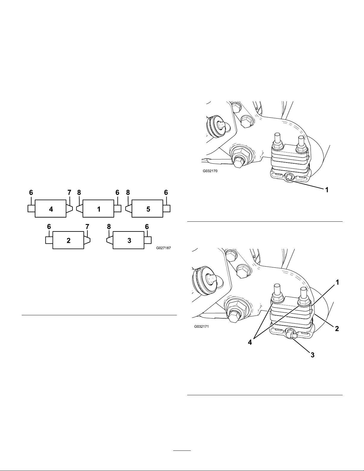
Allcuttingunitsareshippedwiththecounterweight
mountedtotheleftendofthecuttingunit.Referto
Figure1todeterminethepositionoftherollerbrush
andreelmotors.
InstallingtheRoller-Brush
Assembly
1.Ifthecuttingunitsareinstalledonthetraction
unit,parkthemachineonalevelsurface,
engagetheparkingbrake,shutofftheengine,
andremovethekey.
2.Removethegreasettingfortherollerfromthe
sideofthecuttingunitthathastheroller-brush
housing(Figure3).
Figure1
1.Cuttingunit15.Cuttingunit5
2.Cuttingunit2
3.Cuttingunit3
4.Cuttingunit48.Leftroller-brushdrive
6.Reelmotor
7.Rightroller-brushdrive
assembly
assembly
Note:Theseinstructionsandillustrationsshow
theinstallationofthekitoncuttingunitswiththe
universalgroomermountedontheleftendofthe
cuttingunit.
g032170
Figure2
1.Greasetting
3.Installthe90-degreegreasettingsothatit
facesrearward(Figure2).
g027187
g032171
Figure3
1.6mm(1/4inch)spacer3.90-degreegreasetting
2.Side-platemountingange4.Flangelocknuts(remove)
4.Removethe2angelocknutssecuringeach
rollerbrackettothesideplates,aswellasany
6mm(1/4inch)spacerspositionedonthe
topsideoftheside-platemountingange
(Figure3).
2
Page 3
Note:Donotremovethebolts.Keeptheange
locknutsforfutureassembly .
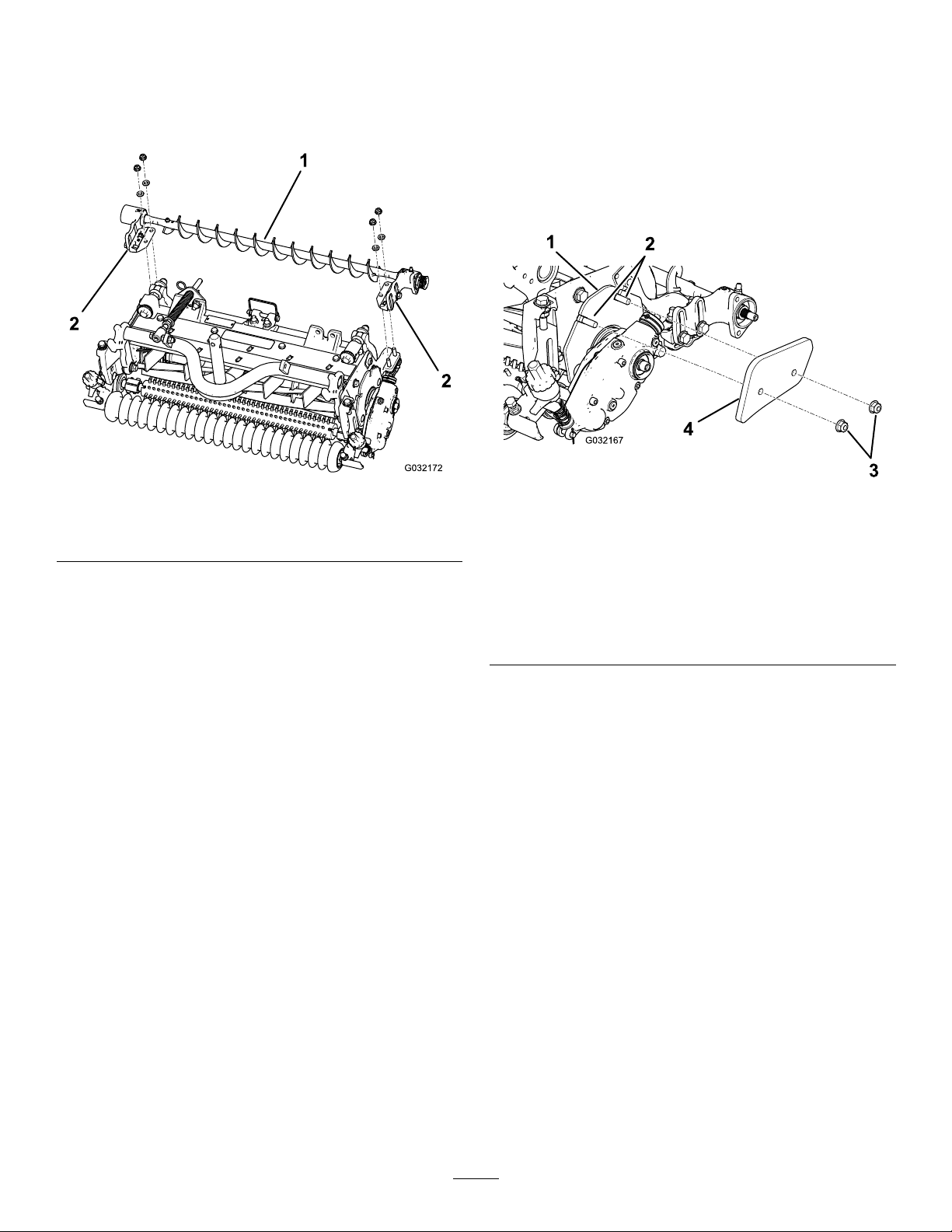
5.Positiontheleftorrightroller-brush-assembly
mountingbracketsontotheroller-bracketbolts
(Figure4).
InstallingtheWeight
IncludedinKit133-0153
(5-inchHydraulicallyDriven
CuttingUnits)
InstalltheweighttothecuttingunitasshowninFigure
5(partsincludedwithbrushkitModel133-0153).
Figure4
1.Leftroller-brushassembly
2.Roller-brushmounting
bracket
Important:Attachthemountingbrackets
fortheroller-brushassemblydirectlyto
thetopsurfaceoftheside-platemounting
angeofthecuttingunit.Donotputspacers
betweentheroller-brushmountingbrackets
andtheside-platemountinganges.Save
theadditional6mm(1/4inch)spacersfor
potentiallateruse.
6.Securethebrush-assemblymountingbrackets
tothecutting-unitsideplateswiththepreviously
removednuts.
g032172
Figure5
Partsincludedwithbrushkit133-0153
5-inchhydraulicallydriven
1.Weightplate
2.Carriagebolts(5/16x1
inch)
3.Flangenuts(5/16inch),
torqueto20to26N∙m(15
to19ft-lb)
4.Weight
g032167
3
Page 4
InstallingtheAdditional
InstallingtheRoller-Brush
WeightPartsNotIncluded
intheKit(5-inchElectrically
DrivenCuttingUnits;7-inch
HydraulicallyorElectrically
DrivenCuttingUnits)
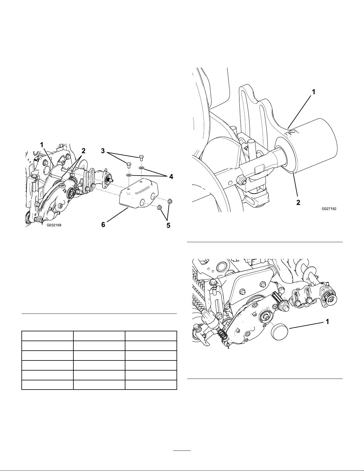
Installtheweightpartstothecuttingunitasshownin
Figure6;refertoAdditionalPartsThatNeedtobe
Ordered(page4).
Ifinstallingbrushkit133-0153,discardtheweightand
fastenersincludedwiththebrushkit(donotuse).
Plate
1.Slidetheexcludersealoutwarduntilthelipseals
areinlightcontactwitheachbearinghousing
(Figure7).
Figure6
Additionalpartsthatneedtobeordered
5-inchelectricallydriven,
7-inchhydraulicallyorelectricallydriven
1.Weightplate
2.Carriagebolts(5/16x2
inch)—PartNo.3230-6
3.Bolts(5/16x1/2
inch)—PartNo.322-1
4.Washers(5/16inch)—Part
No.3256-23
5.Flangenuts(5/16
inch)—PartNo.104-8300
6.Weight—PartNo.
132-0735-03
AdditionalPartsThatNeedtobeOrdered
PartPartNo.
Weight132-0735-031
Carriagebolt
Bolt322-12
Washer3256-232
Flangenut104-83002
3230-62
g027192
Figure7
g032168
Quantity
1.Bearinghousing2.Excluderseal
2.Removethecapfromthegroomerdrivebox.
g283858
Figure8
1.Cap
3.Ensurethattheroller-brushpivotplateis
conguredsothattheidler-pulleyassemblyis
installedonthebottomasshowninFigure9.
Tochangetheroller-brushpivotplatetoa
right-driveconguration,refertoFigure10.
4
Page 5
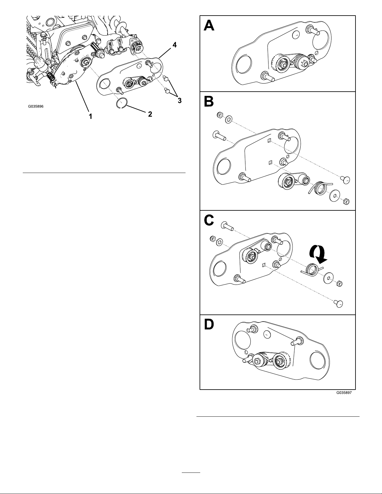
Figure9
1.Roller-brushhousing3.Bolts
2.Retainingring4.Roller-brushpivotplate
(left-driveconguration
shown)
g035896
Figure10
4.Aligntheroller-brushpivotplateasshownin
Figure9.
5
g035897
Page 6

5.Apply242Loctite(blue)tothe2bolts(5/16x1/2
inch)andusethemtomountthebrushplateto
theroller-brush-bearinghousing(Figure9).
PositioningtheRoller
Brush
Note:T orquetheboltsto20to26N∙m(15to
19ft-lb).
6.Securethebrushplatetotheroller-brush
housingwiththeretainingring(Figure9).
7.Ensurethattheroller-brushplateisparallelto
thecutting-unitsideplate.Ifitisnotparallel,
proceedasfollows:
A.Loosenthe2angelocknutssecuring
theroller-brushmountingbrackettothe
cutting-unitsideplate(Figure11).
B.Rotatetheroller-brush-bearinghousinguntil
thebrushplateisparalleltothecutting-unit
sideplate(Figure11).
C.Tightenthe2angelocknutssecuring
theroller-brushmountingbrackettothe
cutting-unitsideplate(Figure11).
1.Loosenthe2boltssecuringeach
roller-brush-bearinghousingtotheroller-brush
mountingbracket(Figure1 1).
Note:Theboltsshouldbeloosefromthe
factory.
2.Positiontherollerbrushsothatitisjusttouching
orrestingontherearroller(Figure12).
Important:Theroller-brushshaftmustnot
contactthecutting-unitsideplate.
Important:Heavybrushcontactonthe
rollercausesprematurebrushwear.
Figure11
1.Loosentheseboltsforpositioningtherollerbrush.
2.Loosenthesenutsformakingtheroller-brushplateparallel.
g032002
Figure12
1.Bearinghousing(some
partsnotshown)
2.Sideplate
3.Rollerbrush
4.Ensurethatthereis
clearancehere.
5.Lightcontact
6.Rearroller
7.Greasetting
g027303
Note:Theroller-brushshaftmustbeparallel
totherearroller.
Important:Positionboth
roller-brush-bearinghousingssothat
theyareparalleltothegroundtoensure
clearancefortherear-rollergreasetting.
6
Page 7

3.Tightenthe2boltssecuringeach
roller-brush-bearinghousingtotheroller-brush
mountingbrackets.
InstallingtheDrivePulley
andtheBelt
1.Restrainthereelforinstallation;Restrainingthe
ReelforInstallingThreadedInserts(page12).
2.Installthedrivepulleyontothegroomershaft
(Figure13).
g192353
Figure14
1.Drivepulley3.Belt
2.Idler-pulleyassembly4.Drivenpulley
•Startthebeltonthedrivenpulley(Figure
15).
•Usea9/16-inchdeep-wellsockettorotate
thebrushassemblyandguidethebeltonto
thedrivenpulley(Figure15).
Figure13
1.Drivepulley2.Flange-headbolt—torque
to20to26N∙m(15to19
ft-lb)
3.Apply242Loctite(blue)totheange-headbolt
andusethebolttosecurethepulleytothe
driveshaft;refertoFigure13.
Note:Torquetheboltto20to26N∙m(15to
19ft-lb).
Important:Ifyoudonotproperlytorquethe
bolt,theboltwillcomeloose.
4.Installthebeltontothepulleysasfollows:
•Loopthebeltaroundthedrivepulleyand
thenoverthetopoftheidlerpulley(Figure
14).
g192352
g020390
Figure15
1.Belt
2.9/16-inchdeep-wellsocket
Important:Ensurethattheribsonthebelt
areproperlyseatedinthegroovesineach
pulleyandthatthebeltisinthecenterofthe
idlerpulley .
7
Page 8

5.Pushdownontheidlerpulleytoensurethatthe
idler-pulleyassemblypivotsfreely.
CompletingtheInstallation
1.Checkthealignmentofthebeltandpulleys;refer
toCheckingthePulleyAlignment(page10).
2.Slidethebeltcoverontothemountingboltsand
securethecoverwith2angenuts(Figure16).
Important:Donotovertightenthenutsas
damagetothecovermayoccur.
Figure16
1.Setscrewinstalled
2.Setscrewremoved
3.Beltcover
g035892
Figure17
g193167
3.Removethebottomsetscrewfordrainage.
Important:Ensurethatthetopsetscrewis
installed.
4.Lubricatethegreasettingsoneachofthe
rollerbrushbearinghousingswithNo.2lithium
grease(Figure17).
Note:Wipeoffanyexcessgrease,specically
aroundtheexcluderseals.
8
Page 9

InstallingtheHigh
Height-of-CutBrush
(Optional)
Installthehighheight-of-cutbrush(soldseparately)
whentheheightofcutis2.5cm(1inch)ormore(5or
morespacersinstalledbelowtheside-platepad).
1.Ifarollerbrushisinstalledonthecutting
unit,removethe2bolts,washers,andnuts
securingthenon-drive-bearinghousingtothe
bearing-housingmountingbracket(Figure18
andFigure19).
7.Clampthebrushontotheshaftwiththe2J-bolts
andnutspreviouslyremoved(Figure20).
Important:Insertthethreadedendofthe
J-boltsthroughtheouterholesofthebrush
shaftwhilehookingthecurvedendsofthe
J-boltsintotheinnerholes.
8.TorquetheJ-boltlocknutsto2to3N∙m(20to
25in-lb).
Figure18
1.Non-drive-bearinghousing
2.Slidethenon-drive-bearinghousingandthe
excludersealoffthebrushshaft(Figure19).
Figure19
1.Non-drive-bearinghousing
2.Excluderseal
3.Brushshaft
g027200
g027202
Figure20
1.Highheight-of-cutbrush
2.J-bolts
3.Loosenthesebolts.
9.Installtheexcludersealandthe
non-drive-bearinghousingontothebrush
shaft(Figure19).
10.Mountthenon-drive-bearinghousingtothe
bearing-housingmountingbracketwiththe2
bolts,washers,andnutspreviouslyremoved.
Note:Becarefulnottoknockthesealspring
off.
11.Tightenthe2bolts,washers,andnutssecuring
g027201
thedrive-bearinghousingtothebearing-housing
mountingbracket.
3.Removethe2J-boltsandthenuts(Figure20).
4.Slidetheexistingbrushoffthebrushshaft
(Figure20).
5.Loosenthe2bolts,washers,andnutssecuring
thedrive-bearinghousingtothebearing-housing
mountingbracket(Figure20).
6.Slidethehighheight-of-cutbrushontothebrush
shaft(Figure20).
9
Page 10

Maintenance
AdjustingthePulley
•Ensurethatthebrushisparalleltotherollerwith
1.5mm(0.060inch)clearancetolightcontact.
•Greasethettingsevery50hoursandafterevery
washing.
•Whenreplacingarollerbrush,torquetheJ-bolts
to2to3N∙m(20to25in-lb).
•Whenreplacingthebrush-shaft-drivenpulley,
torquethenutto36to45N∙m(27to33ft-lb).
•Whenreplacingthebrush-drivepulley ,apply242
Loctite(blue)andtorquetheboltto20to26N∙m
(15to19ft-lb).
Note:Therollerbrush,theidlerbearing,andthebelt
areconsideredconsumableitems.
CheckingthePulley
Alignment
Important:Ensurethatthebeltisproperly
tensionedpriortocheckingthealignment.
1.Layastraightedgealongtheouterfaceofthe
drivepulley(Figure21).
Important:Onlylaythestraightedgeacross
thedrivepulley,donotlayitacrossthedrive
andthedrivenpulley.
2.Ensurethattheouterfacesofthedrivepulley
andthedrivenpulleyareinlinewithin0.76mm
(0.030inch).
Important:Donotusetheidlerpulleyto
checkthealignment.
3.Ifthepulleysarenotaligned,refertoAdjusting
thePulleyAlignment(page10).
Important:Thebeltmayfailprematurelyif
thepulleysarenotproperlyaligned.
Alignment
1.Thedrivenpulley(attheroller-brushshaft)can
moveinorout(Figure22).
Note:Makenoteofwhichwaythepulleyneeds
tomovewhencheckingthebeltalignment;refer
toCheckingthePulleyAlignment(page10).
g193169
Figure22
1.Drivepulley3.Drivenpulley
2.Idlerpulley4.Driven-pulleynut
2.Whilerotatingthereel,whichrotatesthedrive
pulley,prythebeltoffthedrivepulley(Figure22
Important:Wearapaddedgloveorusea
heavyragtorotatethereel.
3.Removethelocknutsecuringthedrivenpulley
tothebrushshaft(Figure22orFigure23).
Note:Usea1/2-inchwrenchontheroller-brush
shaftatstokeepitfromrotating.
Figure21
4.Removethedrivenpulleyfromtheshaft(Figure
23).
5.Ifthepulleyneedstomoveout,adda0.8mm
(0.032inch)thickwasher(Figure23).
Note:Ifthepulleyneedstomovein,remove
theexisting0.8mm(0.032inch)thickwasher.
6.InstallthepulleyasshowninFigure23.
g192350
10
Page 11

Figure23
g193168
1.Locknut
2.Drivenpulley
3.Washer—0.8mm(0.032
inch)thick
4.Spacer
5.Brushshaftats
7.Whileholdingtheatsoftheroller-brushshaft,
securethedrivenpulleyontheshaftwiththe
angenut(3/8–16)previouslyremoved.
Note:Seatthelocknut;thentorqueitto36to
45N∙m(27to33ft-lb).
8.Installthebeltontothepulleysasfollows:
A.Loopthebeltaroundthedrivepulleyand
thenoverthetopoftheidlerpulley(Figure
24).
Figure25
1.Belt
2.9/16-inchdeep-wellsocket
Important:Ensurethattheribsonthebelt
areproperlyseatedinthegroovesineach
pulleyandthatthebeltisinthecenterofthe
idlerpulley .
9.Checkthepulleyalignmentandadjustitif
necessary.
RestrainingtheReel
WARNING
g020390
Figure24
1.Drivepulley3.Drivenpulley
2.Belt4.Idler-pulleyassembly
B.Startthebeltonthedrivenpulley(Figure
24).
C.Usea9/16-inchdeep-wellsockettorotate
thebrushassemblyandguidethebeltonto
thedrivenpulley(Figure25).
Thecuttingreelbladesaresharpandcapable
ofamputatinghandsandfeet.
•Keepyourhandsandfeetoutsideofthe
reel.
g192351
•Ensurethatthereelisrestrainedbefore
servicingit.
RestrainingtheReelforRemoving
ThreadedInserts
1.Loosentheshield-boltontheleftsideofthe
cuttingunitandraisetherearshield(Figure26).
2.Insertalong-handledprybar(recommended
3/8"x12"withscrewdriverhandle)throughthe
11
Page 12

backofthecuttingreel,closesttothesideofthe
cuttingunitthatyouwillbetorquing(Figure26).
3.Placetheprybaragainsttheweldsideofthe
reelsupportplate(Figure26).
Note:Inserttheprybarbetweenthetopofthe
reelshaftandthebacksof2reelbladessothat
thereelwillnotmove.
Important:Donotcontactthecuttingedge
ofanybladeswiththeprybar;thismay
damagethecuttingedgeand/orcauseahigh
blade.
Important:Theinsertontheleftsideof
thecuttingunithasleft-handthreads.The
insertontherightsideofthecuttingunithas
right-handthreads.
RestrainingtheReelforInstalling
ThreadedInserts
1.Insertalong-handledprybar(recommended
3/8"x12"withscrewdriverhandle)throughthe
frontofthecuttingreel,closesttothesideofthe
cuttingunitthatyouwillbetorquing(Figure27).
2.Placetheprybaragainsttheweldsideofthe
internalcuttingreelreinforcement(Figure27).
Note:Theprybarshouldcontactabladeatthe
front,thereelshaft,andabladeatthebackof
thebackofthereel,lockingitinplace.
Important:Donotcontactthecuttingedge
ofanybladeswiththeprybar;thismay
damagethecuttingedgeand/orcauseahigh
blade.
Important:Theinsertontheleftsideof
thecuttingunithasleft-handthreads.The
insertontherightsideofthecuttingunithas
right-handthreads.
Figure26
1.Threadedinsertfor
removal
2.Loosentheshieldbolt.5.Reelsupportplate
3.Rearshield6.Prybarinsertedalong
4.Reelshaft
theweldsideofthereel
supportplate.
4.Restthehandleoftheprybaragainsttherear
roller.
5.Completetheremovalofthethreadedinsert
whileensuringthattheprybarstaysinplace,
thenremovetheprybar.
6.Lowertherearshieldandtightentheshield-bolt.
g280383
g280384
Figure27
1.Threadedinsertfor
installation
2.Reelshaft
3.Weldsideofsupportplate
4.Prybar
3.Restthehandleoftheprybaragainsttheroller
4.Pertheinsert’sinstallationinstructionsand
torquerequirements,completetheinstallationof
thethreadedinsertwhileensuringthatthepry
barstaysinplace,thenremovetheprybar.
12
Page 13

Notes:
Page 14

Notes:
Page 15

DeclarationofIncorporation
TheT oroCompany ,8111LyndaleAve.South,Bloomington,MN,USAdeclaresthatthefollowingunit(s)
conform(s)tothedirectiveslisted,wheninstalledinaccordancewiththeaccompanyinginstructionsontocertain
ToromodelsasindicatedontherelevantDeclarationsofConformity .
ModelNo.
133-0153
133-0154
SerialNo.
—
—
ProductDescriptionInvoiceDescription
RearRollerBrushMVPKit,
Reelmaster3555,5010,
and5010-HSeries22-inch
CuttingUnitwith5-inchReel
andUniversalGroomer
RearRollerBrushMVPKit,
Reelmaster3575or5010-H
Series22-inchCutting
Unitwith7-inchReeland
UniversalGroomer
RM5010/RM35555"22"
RRB(UNIVSL)MVPKIT
RM5010/RM35757"22"
RRB(UNIVSL)MVPKIT
GeneralDescription
RollerBrushKit
RollerBrushKit
Directive
2006/42/EC
2006/42/EC
RelevanttechnicaldocumentationhasbeencompiledasrequiredperPartBofAnnexVIIof2006/42/EC.
Wewillundertaketotransmit,inresponsetorequestsbynationalauthorities,relevantinformationonthispartly
completedmachinery.Themethodoftransmissionshallbeelectronictransmittal.
ThismachineryshallnotbeputintoserviceuntilincorporatedintoapprovedT oromodelsasindicatedonthe
associatedDeclarationofConformityandinaccordancewithallinstructions,wherebyitcanbedeclaredin
conformitywithallrelevantDirectives.
Certied:
AuthorizedRepresentative:
MarcelDutrieux
ManagerEuropeanProductIntegrity
ToroEuropeNV
Nijverheidsstraat5
2260Oevel
Belgium
JohnHeckel
Sr.EngineeringManager
811 1LyndaleAve.South
Bloomington,MN55420,USA
February14,2019
Page 16

 Loading...