

Page 1
PowerDeckLiftKit
ZMaster3000,5000,and6000SeriesMowers
ModelNo.132-5986
WARNING
CALIFORNIA
Proposition65Warning
ThisproductcontainsachemicalorchemicalsknowntotheStateofCaliforniato
causecancer,birthdefects,orreproductiveharm.
Note:Determinetheleftandrightsidesofthemachinefromthenormaloperatingposition.
Note:ThiskitisnotcompatiblewithmachinesthathavetheMyRide™suspensionsystem.
Safety
FormNo.3405-296RevA
InstallationInstructions
SafetyandInstructionalDecals
Safetydecalsandinstructionsareeasilyvisibletotheoperatorandarelocatednearanyareaofpotentialdanger.
Replaceanydecalthatisdamagedorlost.
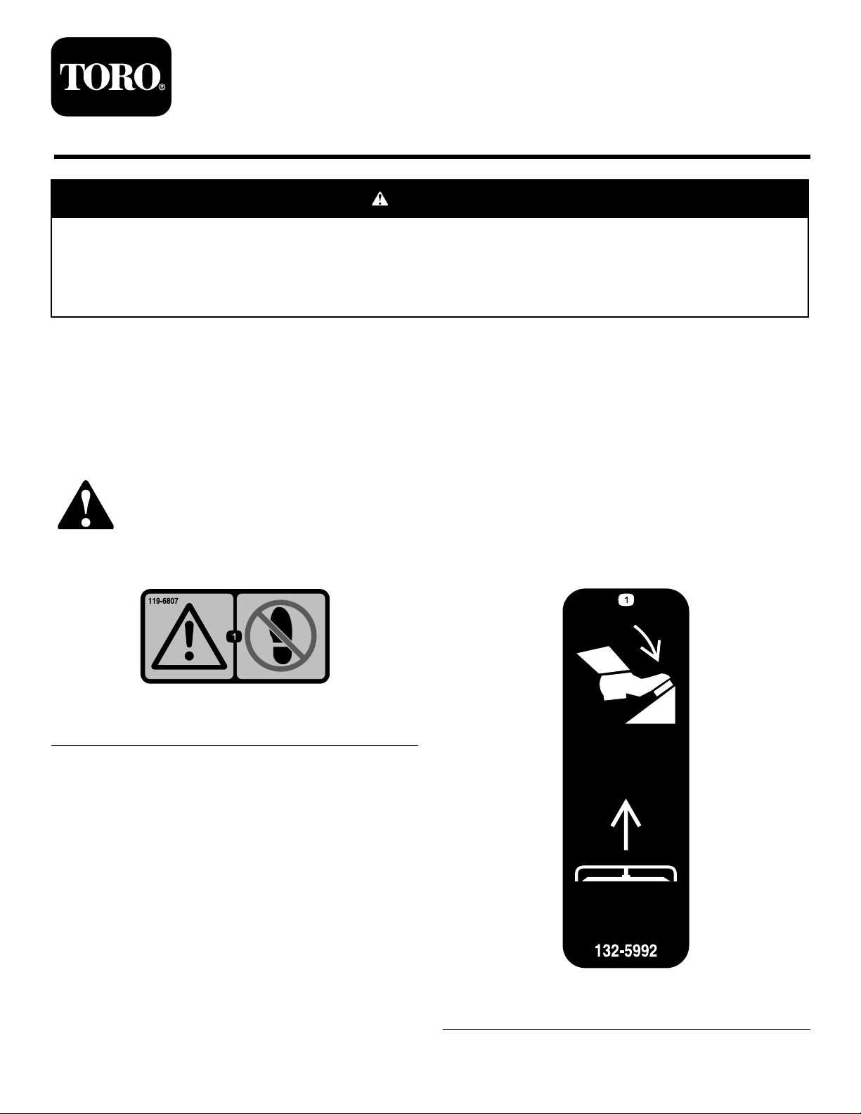
119–6807
1.Warning—nostep
©2016—TheToro®Company
8111LyndaleAvenueSouth
Bloomington,MN55420
Registeratwww.T oro.com.
132-5992
1.Pressdownonthepedaltoliftthedeck.
OriginalInstructions(EN)
PrintedintheUSA
AllRightsReserved
*3405-296*A
Page 2

Installation
LooseParts
Usethechartbelowtoverifythatallpartshavebeenshipped.
ProcedureDescription
1
2
3
4
5
6
Nopartsrequired
Deckfootpedal
Switchtemplate
Momentaryswitch1
Powerliftfootpedal
Screw(1/4x3/4inch)
Flatwasher(1/4inch)
Whiz-locknut(1/4inch)
ZMaster6000seriestemplate1
ZMaster3000/5000seriestemplate
Actuatorbracket1
Screw(7/16x4–1/2inches)
Springdiscwasher(7/16inch)
Whiz-locknut(7/16inch)
Screw(3/8x3–1/2inches);forZMaster
6000seriesunitsonly
Conediscwasher
Whiz-locknut(3/8inch)
Screw(3/8x3–1/4inches);forZMaster
3000and5000seriesunitsonly
Nylocnut1
Frontdeckliftbracket
Screw(1/2x6–1/2inches)
Springdiscwasher(1/2inch)
Locknut(1/2inch)
Actuator1
Clevispin
Cotterpin
Actuatorsideplate2
Flatwasher(1/2inch)
Spacer
Screw(1/2x2–1/2inches)
Wireharness1
Cabletie
Fuse,25A1
Fuse,30A1
Qty.
Use
–
1
1
1
2
2
2
1
1
1
1
1
1
1
1
1
2
2
3
2
2
2
2
1
8
Preparethemachine.
Installthedeckfootpedal.
Installthepowerliftfootpedaland
switch.
Installtheactuatorbracket.
Installtheactuator.
Installthedeckliftharness.
7
8
Nopartsrequired
Nopartsrequired
2
–
–
Completetheinstallation.
Makethenaldeckliftadjustment.
Page 3
1
2
PreparingtheMachine
NoPartsRequired
Procedure
1.Parkthemachineonalevelsurface,disengagethePTO ,
movethemotion-controlleverstotheNEUTRAL-LOCK
position,shutofftheengine,settheparkingbrake,and
removethekeyfromtheignitionswitch.
CAUTION
Ifyouleavethekeyintheignitionswitch,
someonecouldaccidentlystarttheengineand
seriouslyinjureyouorbystanders.
Removethekeyfromtheignitionswitch
beforeyouperformanymaintenance.
2.Disconnectthenegativecablefromthebatterypost;
refertotheOperator’ sManualforyourmachine.
InstallingtheDeckFootPedal
Partsneededforthisprocedure:
1
Deckfootpedal
Procedure
WARNING
InstallingthepowerliftfootpedalonZMaster3000,
5000,and6000seriesmowerswithoutreplacingthe
deckfootpedalcouldresultinseriousinjury.
Replacethedeckfootpedalonallunits.
Note:Usetheexistinghardware.
WARNING
Incorrectbatterycableroutingcoulddamage
themachineandcablescausingsparks.
Sparkscancausethebatterygassesto
explode,resultinginpersonalinjury.
•Alwaysdisconnectthenegative(black)
batterycablebeforedisconnectingthe
positive(red)cable.
•Alwaysconnectthepositive(red)battery
cablebeforeconnectingthenegative
(black)cable.
3.Disconnectthepositivecablefromthebatterypost;
refertotheOperator’ sManualforyourmachine.
4.Removethespark-plugwirefromtheterminalofthe
sparkplug.
Figure1
3
Page 4
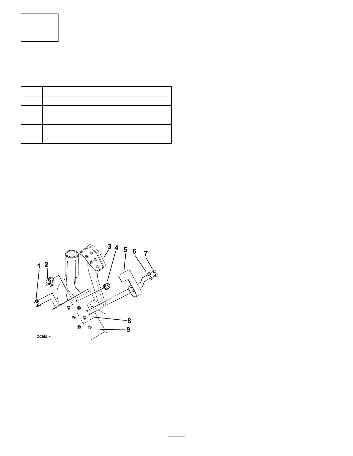
4.Insertthebottomhalfoftheswitchthroughthe
undersideofthetoeboard,makingsurethecontacts
3
pointdownward(Figure2).Screwonthetophalfof
theswitchhand-tight.Donotovertighten.
InstallingthePowerLiftFoot
PedalandMomentarySwitch
Partsneededforthisprocedure:
1
Switchtemplate
1Momentaryswitch
1
Powerliftfootpedal
2
Screw(1/4x3/4inch)
2
Flatwasher(1/4inch)
2
Whiz-locknut(1/4inch)
Procedure
1.Raiseandlockthedeckinthe14cm(5–1/2inch)
transportposition.
2.Cutouttheswitchtemplate,alignthetemplateas
showninFigure2,centerpunchtheholes,anddrill
theholesasfollows:
•Fortheswitch-mountinghole,drillahole(5/8inch
diameter)throughthetoeboard.
5.Handtightenthenutonthebottomhalfoftheswitch
untilitrestsagainsttheundersideofthetoeboard.Do
notovertighten.
6.Installthepowerliftfootpedalusing2screws(1/4x
3/4inch),2atwashers(1/4inch),and2whiz-lock
nuts(1/4inch)asshowninFigure2.
•Forthepowerliftfootpedalmountingholes,drill2
holes(11/32inchdiameter)throughthetoeboard.
Figure2
1.Whiz-locknut(1/4inch)6.Washer(1/4inch)
2.Switch—bottomhalf7.Screw(1/4x3/4inch)
3.Deckfootpedal8.Switchtemplate
4.Switch—tophalf
5.Powerliftfootpedal
9.Toeboard
3.Unscrewthetophalfoftheswitchfromthebottom
halfandunscrewthenutfromthebottomhalfuntilit
stops.
4
Page 5

Note:Ifthehardwareisdifculttoremove,cutoff
thebolthead.
4
InstallingtheActuatorBracket
Partsneededforthisprocedure:
1ZMaster6000seriestemplate
1
ZMaster3000/5000seriestemplate
1Actuatorbracket
1
Screw(7/16x4–1/2inches)
1
Springdiscwasher(7/16inch)
1
Whiz-locknut(7/16inch)
Screw(3/8x3–1/2inches);forZMaster6000series
1
unitsonly
1
Conediscwasher
1
Whiz-locknut(3/8inch)
Screw(3/8x3–1/4inches);forZMaster3000and
1
5000seriesunitsonly
1Nylocnut
Procedure
1.Raiseandlockthedeckinthe14cm(5–1/2inch)
transportposition.
2.Inserttheheight-adjustmentpinintothe14cm(5–1/2
inch)holetoassurethedeckislockedinthefull-up
(transport)position.
3.Ontheleftsideoftheunit,measurethedistance
betweenthenutontheendofthespringandthe
bracket(Figure3).Notethismeasurement.
5.Removeandretainthefrontspringhardwareandthe
sidespring.
6.Cutouttheappropriatereardeckliftarmtemplate,
alignthetemplateasshowninFigure4,centerpunch
thehole,anddrilltheholeasfollows:
•ForZMaster6000seriesunits,drillahole(25/64
or13/32inchdiameter).
•ForZMaster3000and5000seriesunits,drillapilot
hole(5/16inchdiameter)andtap3/8-16UNC.
Note:Aat-bottomtapisnecessarytofullythread
thehole.
Figure4
1.ZMaster3000/5000series
reardeckliftarm
2.Template4.Bottomhole
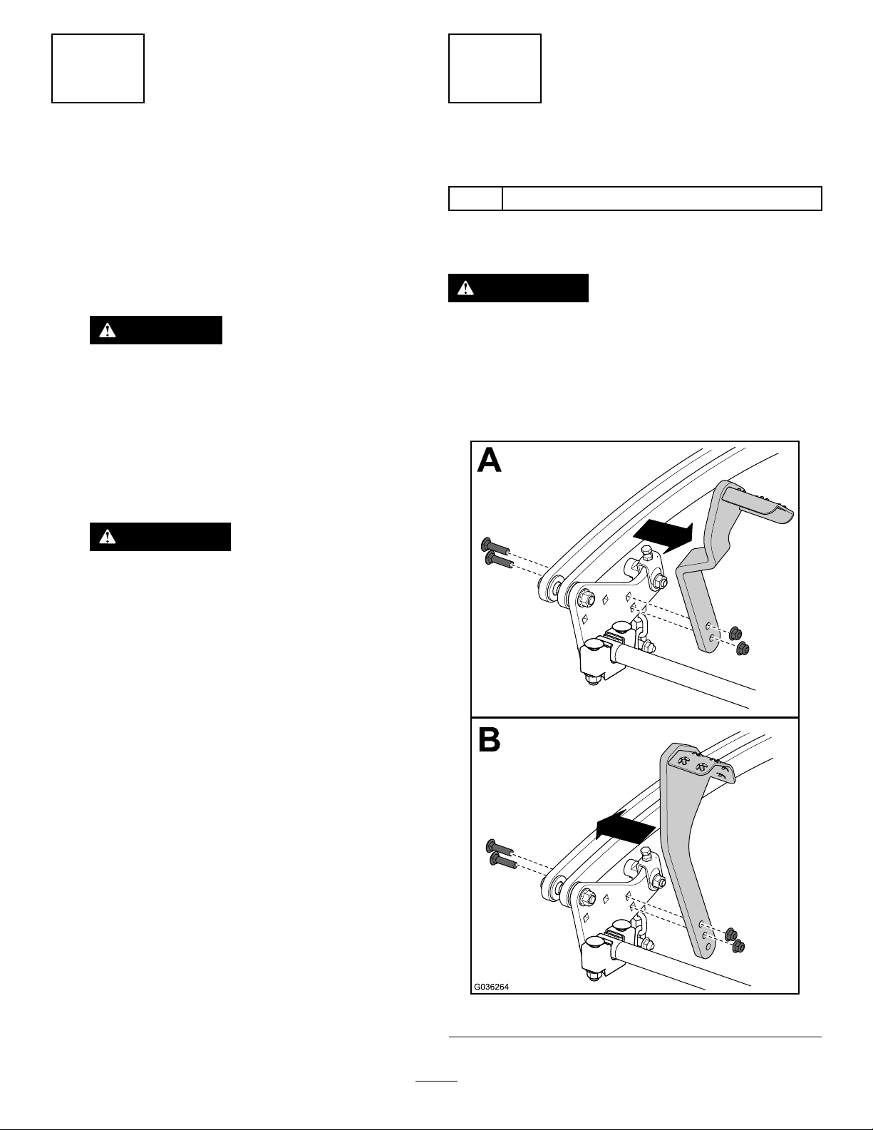
7.Installtheactuatorbrackettothereardeckliftarmby
performingthefollowing:
A.Alignthetopholeoftheactuatorbracketandrear
deckliftarm.
B.Attachtheactuatorbrackettothereardecklift
armwithascrew(7/16x4–1/2inches),spring
discwasher(7/16inch),andwhiz-locknut(7/16
inch)asshowninFigure5.Handtightenagainst
thebracket.
3.Zmaster6000seriesrear
deckliftarm
Figure3
1.Measuredistance
2.Bracket5.Fronthardware
3.Nut6.Rearhardware
4.Sidespring
4.Removeandretaintherearhardwareholdingthe
spring.
Figure5
1.Whiz-locknut(7/16inch)3.Springdiscwasher(7/16
2.Actuatorbracket
5
inch);conetowardsbolt
head
4.Screw(7/16x4–1/2
inches)
Page 6

C.Installhardwareintobottomholeoftheactuator
bracketbyperformingthefollowing:
•ForZMaster6000seriesunits,installascrew
(3/8x3–1/2inches),conediscwasher,
andwhiz-locknut(3/8inch)andtighten
hand-tight.
•ForZMaster3000and5000seriesunits,
installascrew(3/8x3–1/4inches)andcone
discwasher.
8.Torquethescrewsfromstep7accordingtothe
followingtable.
ScrewSizeTorqueSpecication
7/16inch61to75N∙m(45to55ft-lb)
3/8inch37to45N∙m(27to33ft-lb)
9.Installthesidespringbyplacingtherearhookonto
thescrew .Installthenylocnutandleavea9mm(0.35
inch)gapbetweenthenylocnutandwhiz-locknut
(7/16inch)asshowninFigure6.
5
InstallingtheActuator
Partsneededforthisprocedure:
1
Frontdeckliftbracket
2
Screw(1/2x6–1/2inches)
2
Springdiscwasher(1/2inch)
3
Locknut(1/2inch)
1Actuator
2
Clevispin
2
Cotterpin
2Actuatorsideplate
2
Flatwasher(1/2inch)
2
Spacer
1
Screw(1/2x2–1/2inches)
Procedure
Figure6
1.Nylocnut
2.Screw(7/16x4–1/2
inches)
10.Haveahelperpressdownonthedeckpedalandhold
thedecktothefull-up(transport)position.
11.Installthefrontboltofthesidespring,usethe
measurementrecordedinstep3tosetthegapbetween
thenutontheendofthespringandthebracket(see
Figure3),andtightenorloosenthespringboltuntil
theappropriategapisreached.
12.Yourhelpercannowreleasethedeckandallowitto
returntotheTRANSPORT-LOCKposition.
3.Whiz-locknut(7/16inch)
4.9mm(0.35inch)gap
1.Raisetheleftsideofthedeckandsupportitwithjack
stands.Makesurethatthereisnoweightontheleft
frontdeckliftlinkadjuster.
WARNING
Raisingthemowerforserviceormaintenance
relyingsolelyonmechanicalorhydraulic
jackscouldbedangerous.Themechanicalor
hydraulicjacksmaynotbeenoughsupport
ormaymalfunctionallowingtheunittofall,
whichcouldcauseinjury.
Donotrelysolelyonmechanicalorhydraulic
jacksforsupport.Useadequatejackstands
orequivalentsupport.
2.Raiseandlockthedeckinthe14cm(5–1/2inch)
transportposition.
3.Inserttheheight-adjustmentpinintothe14cm(5–1/2
inch)holetoassurethedeckislockedinthefull-up
(transport)position.
4.Removethehardwarefromtheleft,frontcross-shaft
support.
6
Page 7

5.Installthefrontdeckliftbracketusing2screws(1/2x
6–1/2inches),2springdiscwashers(1/2inch),and2
locknuts(1/2inch)asshowninFigure7.Torquethe
screwsto91to113N∙m(67to83ft-lb).
7.InstalltherearactuatorsideplatesasshowninFigure9.
Figure9
Figure7
1.Screw(1/2x6–1/2inches)4.Left,frontcross-shaft
2.Springdiscwasher(1/2
inch);conetowardsbolt
head
3.Frontdeckliftbracket
support
5.Locknut(1/2inch)
6.Installtheactuatoronthefront,deck-liftbracketusing
theclevispinandhairpincotter(Figure8).
Note:Makesurethatthemotorispointingdown.
1.Clevispin
2.Flatwasher(1/2inch)
3.Actuatorsideplates
4.Spacer8.Locknut(1/2inch)
5.Actuatorbracket
6.Hairpincotter
7.Screw(1/2x2–1/2inches)
8.Iftheactuatorholedoesnotalignwiththe
actuator-side-platehole,turntheendoftheactuator
clockwiseorcounterclockwiseuntilitalignsasshown
inFigure10.
Figure10
1.Actuatorend3.Turntoshorten
2.Turntolengthen
Figure8
1.Front,deck-liftbracket3.Clevispin
2.Actuator4.Hairpincotter
9.Installtheactuatorsideplatestotheactuatorbracket
asshowninFigure9.
Note:Usethetopcenterholeposition.
10.Carefullyremovethejackstand.
7
Page 8

6
12
3
4
5
7
5
8
9
10
6
5
G012951
InstallingtheDeckLiftHarness
Partsneededforthisprocedure:
1Wireharness
8
Cabletie
1Fuse,25A
1Fuse,30A
Procedure
2.Connecttheotherendtotheactuatorharness.Push
thedeckliftandactuatorharnessconnectioninside
thetoeboard(Figure12).
Harnessroutingoverview:
Figure11
1.Actuator6.Floorpan
2.Connectactuatorand
deckliftharness
3.Deckliftharness8.Controlpanelfront
4.Connectswitchtodecklift
harness
5.Cabletie10.Connectdeckliftharness
7.Rightmotioncontrolpanel
opening
9.Controlpanelrearopening
toaccessory
Figure12
1.Toeboard3.Actuatorharness
2.Deckliftharness
3.Removethe15Aaccessoryfusefromthefuseboxand
replaceitwiththe25Afuse.
4.Removethe25Amainfusefromthefuseboxand
replaceitwiththe30Afuse.
5.Removeandretainthehardwarefromthecontrol
panel,carefullyremovethecontrolpanel,andremove
thecapfromtheaccessoryplug.
6.Routethedeckliftharnessundertherightsideofthe
oorpanelalongthesideoftheframesothatitjoins
withthemainsystemwireharness.
Note:Usecabletiestosecurethewireharnesstothe
machineasshowninFigure11.
7.Insertthedeckliftharnessthroughthefrontopening
ofthecontrolpanel,routeitthroughtherearopening
ofthecontrolpanel,andconnectittotheaccessory
harnessplug.
8.Ifmultipleaccessoriesarebeingused,anadd-on
accessoryharnesskitisrequired(PartNo.109-9798).
9.Installthepreviouslyremovedcontrolpanelwiththe
correspondinghardware.
4.Actuator
1.Plugthedeckliftharnessintotheswitchandroute
theharnessaroundthecross-shaftusingcabletiesto
securetheharnessasnecessary.
8
Page 9

7
CompletingtheInstallation
NoPartsRequired
Procedure
1.Connectthepositivebatterycabletothepositivepost
ofthebattery;refertotheOperator’sManualforyour
machine.
2.Iftheactuatordoesnotraisethedeckhighenoughto
getoutoftheTRANSPORT-LOCKposition,movethe
rearclevispinbackaholeasshowninFigure13.
WARNING
Incorrectbatterycableroutingcoulddamage
themachineandcablescausingsparks.
Sparkscancausethebatterygassesto
explode,resultinginpersonalinjury.
•Alwaysdisconnectthenegative(black)
batterycablebeforedisconnectingthe
positive(red)cable.
•Alwaysconnectthepositive(red)battery
cablebeforeconnectingthenegative
(black)cable.
2.Connectthenegativecablefromthebatterypost;refer
totheOperator’sManualforyourmachine.
3.Connectthespark-plugwiretotheterminalofthe
sparkplug.
8
Figure13
1.Moveforwardifdeckhits
framestops
2.Initialposition
3.Iftheactuatorraisesthedecktoofarandthedeckhits
theframe(Figure14)priortotheactuatorbeingfully
retracted,anoticeableloudbangingsoundoccursas
theclutchslipserratically.Ifthishappens,movethe
rearclevispinforwardahole;refertoFigure13.
3.Movebackwardif
unabletogetin/outof
TRANSPORT-LOCK
MakingtheFinalDeckLift Adjustment
NoPartsRequired
Procedure
1.Afterthedeckliftkitiscompletelyinstalled,turnonthe
keyandactivatethepowerliftfootpedal.Theactuator
retractsandliftsthedecktothehighestposition.
Note:Theactuatorhasaratchetingslipclutchyou
cannoticeablyhearwhentheactuatorisbeingfully
retracted.Ifthedeckliftisadjustedproperly ,thedeck
liftsoutoftheTRANSPORT-LOCKpositionandthere
isarapidclickingsoundwhentheactuatorisfully
retracted.
Figure14
1.Deckstop3.Actuatorbracket
2.Framestop
4.Ifthedeckdoesnotfallunderitsownweight,lengthen
thedistancebetweenthedeckbracketandsidespring
nutby1/8inch(3mm);refertoFigure3.Testthe
actuatoragain.Repeatthisstepuntilthedeckfalls
underitsownweight.
9
Page 10

Operation
Thepowerdeckliftkitisdesignedtoworkinconjunction
withtheoriginaldeck-lift,height-of-cut,andtransport-lock
mechanismsalreadyonthemower.Whenthepowerdeck
liftkitisproperlyinstalled,anelectricactuatorprovides
apoweredliftingfeaturethatreducestheneedtopush
onthemanualfootleverwhenraisingthedecktothe
TRANSPORT-LOCKposition.However,themanualfootlever
maystillbeusedformanualoverrideofthepoweredsystem,
intheeventitisconvenientornecessarytodoso.
RaisingtheDeckUsingthe PoweredDeckLift
Pressthepowerliftfootpedaltoraisethedecktothe
TRANSPORT-LOCKposition.Theelectricactuatorhasaslip
clutchthatratchetswhenthedeckisfullyraised,andthere
isarapidclickingsoundwhentheclutchisslipping.This
ratchetingsoundisnormalastheactuatorisdesignedto
ratchettoalimiteddegree.
Note:Holdingthepowerliftfootpedalagainsttheswitch
formorethan2seconds,afteritisfullyraised,causesthe
actuatortooverheatandreducesthelifeoftheactuator.It
isrecommendedtolimittheactuatorratchetingtonolonger
than2secondsatatime,witharestingperiodofatleast30
seconds,orexcessiveheatingandactuatordamagemayoccur.
PutthedeckinTRANSPORT-LOCK,orusethemanualfoot
lever,toholdthedeckinplaceforlongerperiodsoftime.
LoweringtheDeckUsingthe PoweredDeckLift
1.Stopthemachineandmovethemotioncontrollevers
outwardtotheNEUTRAL-LOCKposition.
2.DisengagethePTO.
3.WiththedeckintheTRANSPORT-LOCKposition,insert
theheight-adjustmentpinintothedesiredheight-of-cut
setting.
4.Releasepressurefromthetransportlockbypushing
eitherthepowerliftfootpedal,orthemanualdeckfoot
lever,andsimultaneouslypullingonthetransport-lock
rod.
5.Slowlyreleasethepowerliftfootpedalorthemanual
deckliftfootpedal.Whenreleased,thedeckisfree
tofallunderitsownweight,whichback-drivesthe
actuator,untilthedeckstopsontheheight-adjustment
pin.
Note:Ifthedeckdoesnotfallunderitsownweight
orifthedeckhitstheframewhenthedeckisinthe
full-upposition;referto8MakingtheFinalDeckLift
Adjustment(page9).
10
Page 11

Notes:
11
Page 12

 Loading...