

Page 1
DeluxeSeatKit
g018378
1
2
2000SeriesZMaster
ModelNo.132-5972
Installation
LooseParts
Usethechartbelowtoverifythatallpartshavebeenshipped.
FormNo.3397-186RevA
®
RidingMower
InstallationInstructions
ProcedureDescription
1
2
3
Note:Forperformanceandsafety,2000Seriesmachines
with48inchmowerdecksrequireaweightkit(No.121-7576)
afterthedeluxeseatkitisinstalled.Obtainthecorrectweight
kitfromanAuthorizedServiceDealer.
Nopartsrequired
Seat
Spacer
Flangenut(5/16inch)
Cabletie
Nopartsrequired
1
RemovingtheSeat
Qty.
Use
–
1
4
4
4
–
Removetheseat.
Installtheseat.
Testthesafety-interlocksystem.
NoPartsRequired
Procedure
1.Toexposethefrontnuts,movetheseattothefurthest
rearposition.
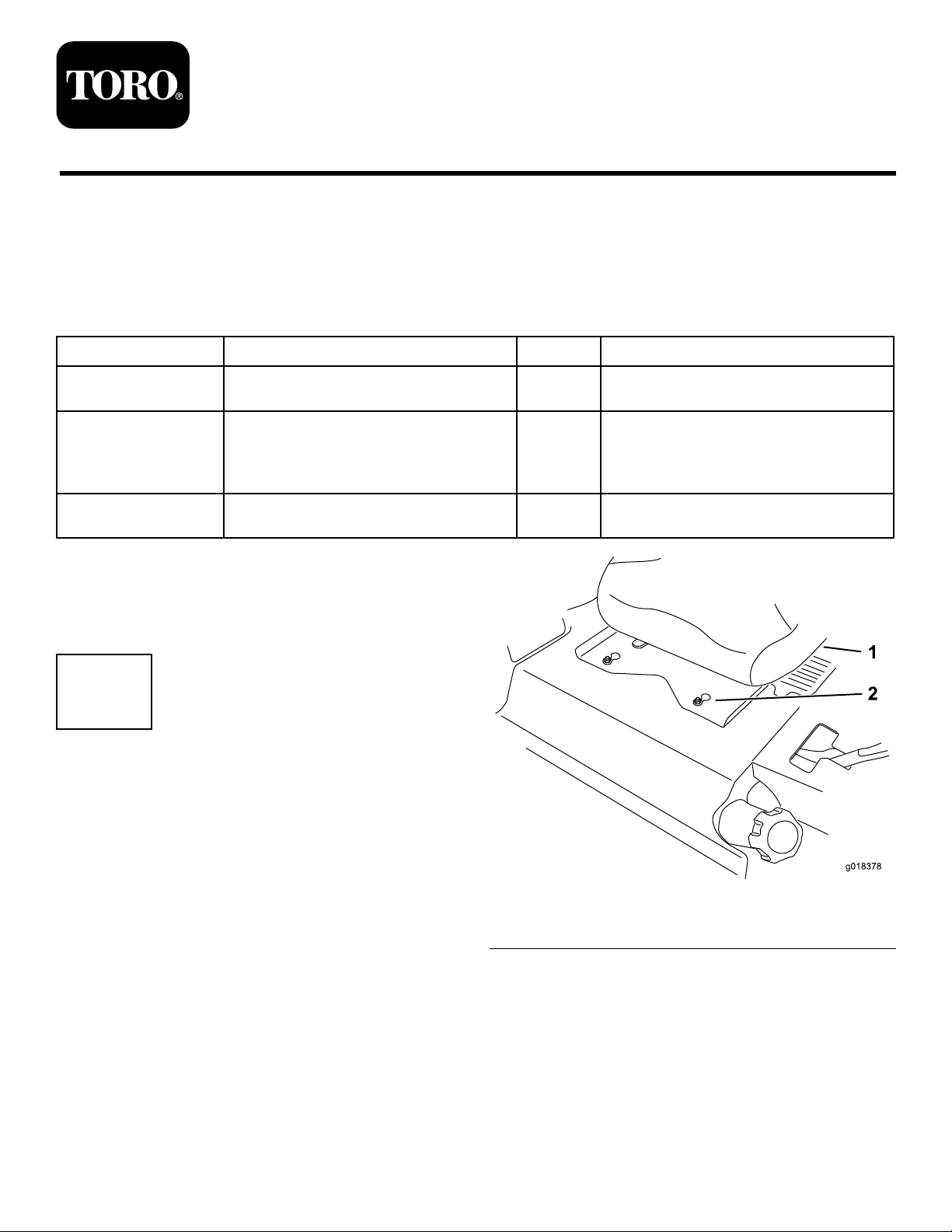
2.Loosenthefrontnuts(Figure1).
3.Toexposetherearnuts,movetheseattothefurthest
forwardposition.
4.Loosentherearnuts.
5.Slidetheseatandseatplateforwardtoallowthefront
nutstogothroughthekeyholes(Figure1).
6.Removetheseatandbasefromthemachine.
7.Unplugtheharnessconnectorfromtheseatswitch
locatedundertheseat.
©2015—TheT oro®Company
8111LyndaleAvenueSouth
Bloomington,MN55420
Registeratwww.T oro.com.
Figure1
1.Existingseat2.Frontnutswithkeyhole
OriginalInstructions(EN)
PrintedintheUSA
AllRightsReserved
*3397-186*A
Page 2
4
g030704
8.Installtheseattothemachineframebyaligningthe
frontnutswiththekeyholeintheseatplate.
2
InstallingtheSeat
Partsneededforthisprocedure:
1
Seat
4
Spacer
4
Flangenut(5/16inch)
4
Cabletie
Procedure
1.Removethepackingcoversguardingtheseatstuds.
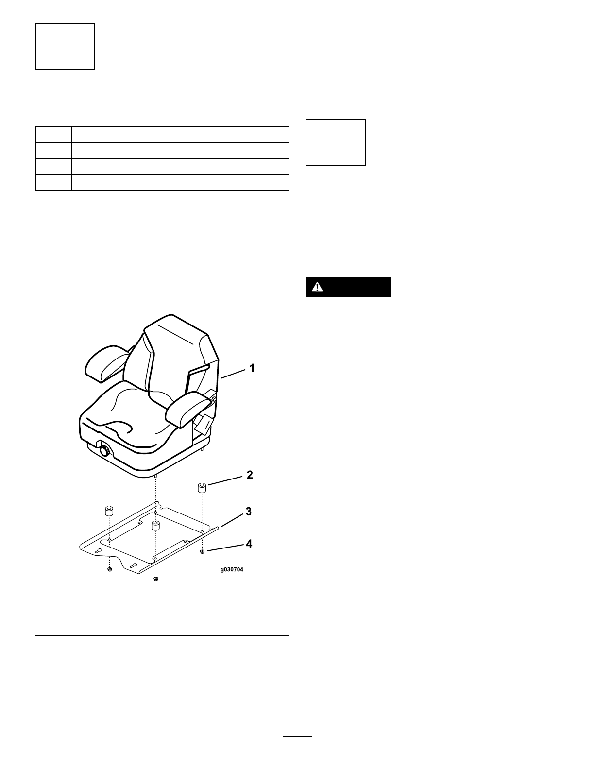
2.Installaspacerontoeachseatstud(Figure2).
3.Securetheseatframetotheseatwith4angenuts
(5/16inch)(Figure2).
4.Torquethenutsto30.5N-m(22.5ft-lb).
9.Slidetheseatandseatplaterearwardtolockthefront
nutsintothekeyholeandtherearnutsintotheslots
(Figure1).
10.Torquethenutsto47.5N-m(35ft-lb).
3
TestingtheSafety-Interlock System
NoPartsRequired
Procedure
CAUTION
Ifthesafety-interlockswitchesaredisconnectedor
damaged,themachinecouldoperateunexpectedly,
causingpersonalinjury.
Figure2
1.Seat3.Seatframe
2.Spacer
5.Plugtheharnessconnectorintotheseatswitchlocated
undertheseattowardthefront.
6.Carefullylowertheseatdownandensurethatyoudo
notpinchthewireharness.
7.Installthecableties.
4.Nut
•Donottamperwiththeinterlockswitches.
•Checktheoperationoftheinterlockswitches
dailyandreplaceanydamagedswitchesbefore
operatingthemachine.
Thesafety-interlocksystemisdesignedtopreventtheengine
fromstartingunless:
•Theparkingbrakeisengaged.
•Theblade-controlswitch(PTO)isdisengaged.
•Themotion-controlleversareintheNEUTRALLOCK
position.
Thesafety-interlocksystemisalsodesignedtostoptheengine
whenthetractioncontrolsaremovedfromtheLOCKED
positionwiththeparkingbrakeengagedorifyourisefrom
theseatwhenthePTOisengaged.
Thehourmeterhassymbolstonotifyyouwhenthe
interlockcomponentisinthecorrectposition.Whenthe
componentisinthecorrectposition,atrianglelightsupin
thecorrespondingsquare.
Testthesafety-interlocksystembeforeyouusethemachine
eachtime.Ifthesafetysystemdoesnotoperateasdescribed
below,haveanAuthorizedServiceDealerrepairthesafety
systemimmediately.
1.1.Sitontheseat,engagetheparkingbrake,andmove
theblade-controlswitch(PTO)totheONposition.
Starttheengine:Theengineshouldnotcrank.
2
Page 3

2.Sitontheseat,engagetheparkingbrakeandmovethe
g019754
g019768
1
blade-controlswitch(PTO)totheOFFposition,and
moveeithermotion-controllever(outoftheNEUTRAL
LOCKposition).
Starttheengine:Theengineshouldnotcrank.Repeat
fortheothermotion-controllever.
3.Sitontheseat,engagetheparkingbrake,movethe
blade-controlswitch(PTO)totheOFFposition,and
movethemotion-controlleverstotheNEUTRALLOCK
position.
Starttheengine,releasetheparkingbrake,engagethe
PTO,andriseupslightlyfromtheseat:Theengine
shouldstop.
4.Sitontheseat,engagetheparkingbrake,movethe
blade-controlswitch(PTO)totheOFFposition,and
movethemotion-controlleverstotheNEUTRALLOCK
position.
Starttheengine,centereithermotion-controllever,and
move(forwardorreverse):Theengineshouldstop.
Repeatfortheothermotion-controllever.
5.Sitontheseat,disengagetheparkingbrake,movethe
blade-controlswitch(PTO)totheOFFposition,and
movethemotion-controlleverstotheNEUTRALLOCK
position.
Operation
PositioningtheSeat
Theseatcanmoveforwardandbackward.Positiontheseat
whereyouhavethebestcontrolofthemachineandaremost
comfortable.
Toadjust,movetheleversidewaystounlocktheseat(Figure
3).
Figure3
ChangingtheSeatSuspension
Starttheengine:Theengineshouldnotcrank.
Theseatisadjustabletoprovideasmoothandcomfortable
ride.Positiontheseatwhereyouaremostcomfortable.
Toadjusttheseat,turntheknobinfronteitherdirectionto
providethebestcomfort(Figure4).
Figure4
1.Seat-suspensionknob
3
Page 4

 Loading...