

Page 1
ManualSprayKit
2015andAfterMulti-Pro5800TurfSprayer
ModelNo.132-5570
LooseParts
Usethechartbelowtoverifythatallpartshavebeenshipped.
FormNo.3396-307RevA
InstallationInstructions
Description
Valvemodule1
Bolt(1/4x5/8inch)
Washer(1/4inch)
Nut(1/4inch)
Speedometer
Wiringharness1
Fuse(10amp)
Proposition65Warning
ThisproductcontainsachemicalorchemicalsknowntotheStateofCaliforniato
causecancer,birthdefects,orreproductiveharm.
Note:YoumayneedaFuseBlockKit(Toropartnumber
92-2641)toprovidepowertothespeedometerifthereareno
openfuseports.ContactyourT oroDistributortopurchase
thiskit.
Qty.
CALIFORNIA
Use
2
2
2
1
1
Installthevalvemodule.
Installthespeedometer.
WARNING
InstallingtheValveModule
1.Positionthemachineonalevelsurface,settheparking
brake,turntheignitionoff,andremovethekey.
CAUTION
Ifyouleavethekeyintheignitionswitch,
someonecouldaccidentlystarttheengineand
seriouslyinjureyouorotherbystanders.
Removethekeyfromtheignitionswitch
beforeyoudoanymaintenance.
2.Disconnectthenegativebatteryterminalfromthe
battery;refertoyourOperator’sManual.
3.Openthehood.
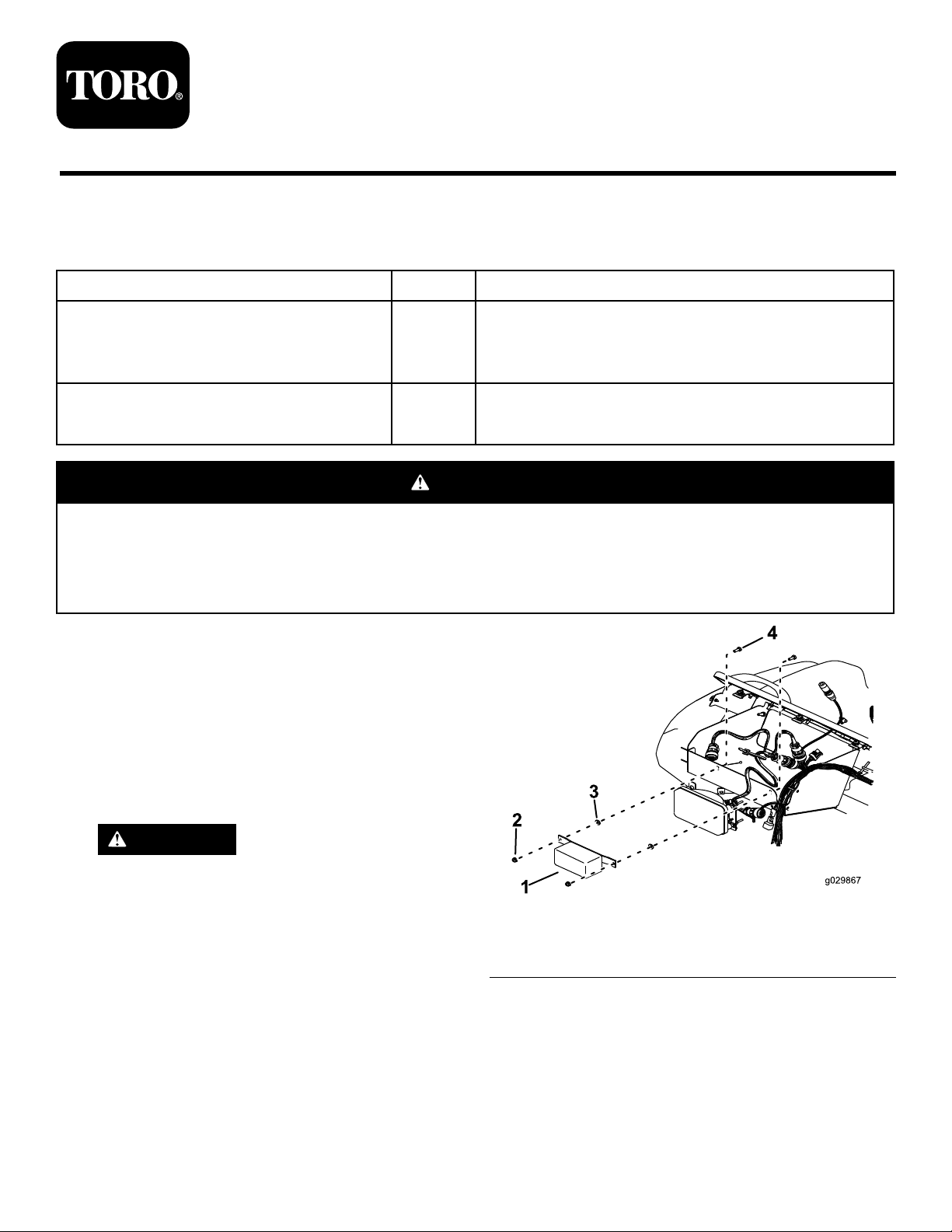
4.Installthevalvemoduletothefrontofthestorage
compartmentusing2bolts,2washers,and2nuts
(Figure1).
©2015—TheT oro®Company
8111LyndaleAvenueSouth
Bloomington,MN55420
Registeratwww.T oro.com.
Figure1
1.Valvemodule3.Washer
2.Nut4.Bolt
OriginalInstructions(EN)
PrintedintheUSA
AllRightsReserved
*3396-307*A
Page 2
InstallingtheSpeedometer
G017083
1
G017084
1
2
G017085
1
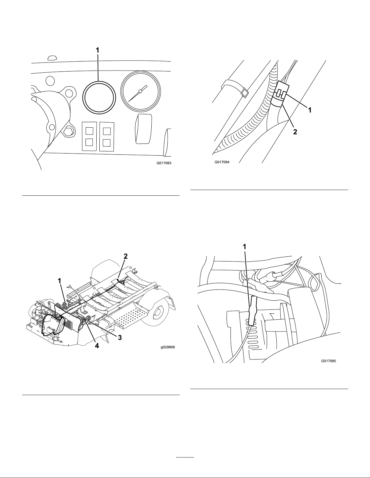
1.Removetheknockoutinthedashofthemachineand
installthespeedometerinitsplaceFigure2.
Figure2
1.Knockout
5.Connectthespeedometerwireharnesstothe
wheel-motorconnectorusingthe3-pinweather-pack
connectorend(Figure4).
Note:Thisconnectionisneartherear,rightfender
ofthevehicle.
Figure4
1.Weather-packconnector2.Wheel-motorconnector
2.Connectthespeedometerplugintothe
speedometer-wiring-harnessconnector.
3.Routethelongerendofthespeedometerwiring
harnessontherightsideofthemachine,followingthe
mainwiringharnessofthemachinetotheright,rear
tire(Figure3).
Figure3
3.Connecttothefuseblock.
4.Connecttothe
ground-terminalblock.
1.Speedometerwiring
2.Connecttothe
harness
wheel-motorconnector.
6.Securethewiringharnesstotheframe.
7.Routetheotherendofthewiretothefuseblockunder
theleftseat(Figure3).
8.Connectthewiretooneoftheavailableterminalsfrom
thefuseblock(Figure5).
Figure5
1.Wireconnectedtoaterminal
4.Unplugthemainwireharnessfromthewheel-motor
connector.
2
Page 3

9.Ifnopowerterminalsontheexistingfuseblockare
G017086
1
2
G017087
1
available,installanadditionalfuseblock(T oropart
number92-2641)andthe10-ampfuse(Figure6).
Figure6
1.Fuseblock
2.Fuse(10amp)
10.Pluginanavailablepowerterminalfromthefuseblock.
11.Connecttheblackwirewitharingterminaltothe
ground-terminalblock(Figure7).
Figure7
1.Ringterminalontheterminalblock
12.Ifnotdonealready ,installthe10-ampfusetothefuse
block.
13.Closethehood.
14.Installthenegativebatteryterminaltothebattery.
3
Page 4

 Loading...