

Page 1
AutomatedRowSelectionKit
2024DirectionalDrill
ModelNo.132-4193
ThisproductcontainsachemicalorchemicalsknowntotheStateofCaliforniato
causecancer,birthdefects,orreproductiveharm.
Safety
SafetyandInstructionalDecals
FormNo.3397-156RevA
InstallationInstructions
WARNING
CALIFORNIA
Proposition65Warning
125-6184
©2015—TheToro®Company
8111LyndaleAvenueSouth
Bloomington,MN55420
Registeratwww.T oro.com.
OriginalInstructions(EN)
PrintedintheUSA
AllRightsReserved
*3397-156*A
Page 2

LooseParts
Usethechartbelowtoverifythatallpartshavebeenshipped.
ProcedureDescription
1
2
3
4
5
6
7
Rotarysensor1
Innersensorbracket1
Outersensorbracket
Bolt(M4-10mm)
Bolt(M8-1.25x20mm)
Locknut(M8)
Camassembly
Flangenut15
Bolt(M10-1.5x30mm)
Bolt(M10-1.5x35mm)
Locknut(M10)
Nut(M10-1mm)
Nut(M4-0.07mm)
Flatwasher2
Bolt(M8-1.25x40mm)
Bolt(M8-1.25x30mm)
Bolt(M5-0.08x25mm)
Nut(M5-0.08mm)
Bolt(M8-1.25x20mm)
Wiringharness1
Cableties
Gasket
Adjustmentblock4
Brace4
Nut(3/8-16inch)
Bolt(3/8-16x11/4inch)
Bolt(3/8-16x1inch)
Spacer
Washer8
Bolt(M12-13/4x70mm)
Bracket1
Plateag
Bolt(M5-0.08x25mm)
Nut(M5)
Cabletie
Valvecap1
Monitorcap1
Decal1
Qty.
16
Use
1
2
2
4
1
3
1
1
1
2
2
2
2
2
2
1
8
4
4
8
8
1
4
4
2
Installtherotarysensor.
Movetheproximitysensorandreplace
theadjustmenthardware.
Installthewiringharness.
Removetherotarypumpsupplyand
drainorices.
Installthethrustmotoranti-rotation
supports.
Installtheproximityswitchbracket.
Installthecapsanddecal.
Parkthemachineonalevelsurface,turnofftheengine,andremovethekey .
2
Page 3
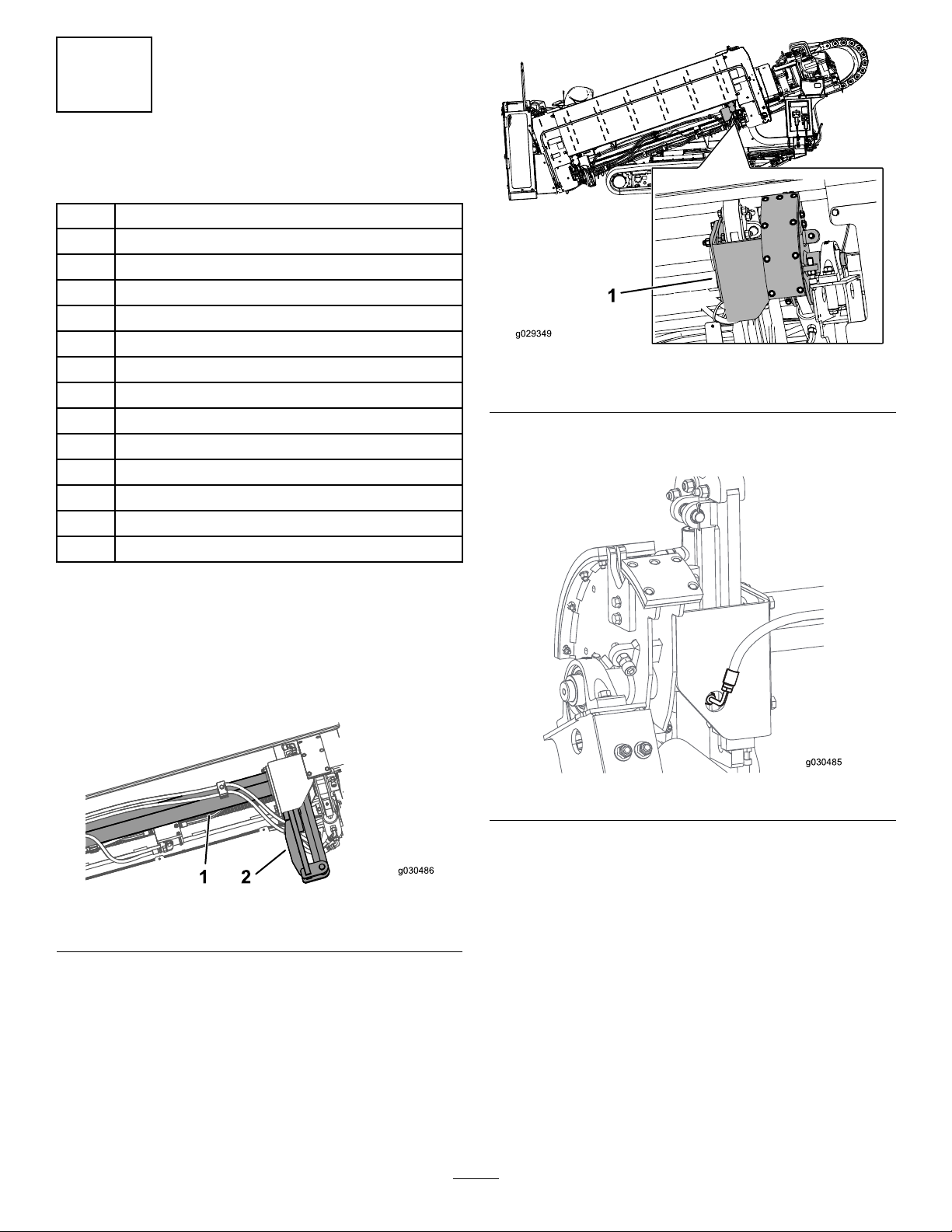
1
g0304 85
InstallingtheRotarySensor
Partsneededforthisprocedure:
1Rotarysensor
1Innersensorbracket
1
Outersensorbracket
2
Bolt(M4-10mm)
2
Bolt(M8-1.25x20mm)
4
Locknut(M8)
1
Camassembly
15Flangenut
3
Bolt(M10-1.5x30mm)
1
Bolt(M10-1.5x35mm)
1
Locknut(M10)
1
Nut(M10-1mm)
2
Nut(M4-0.07mm)
2Flatwasher
Figure2
1.Camassembly
3.Disconnectthehydraulicttingonthefrontsideofthe
camassembly(Figure3).
Procedure
1.Ensurethatthethrustframeisinthehorizontal
position.
2.Supportthecamtubewithanoverheadcraneoroor
jackbeforeproceedingtothenextstep(Figure1).
Figure1
1.Cam-tubeassembly
2.Rod-loaderassembly
Figure3
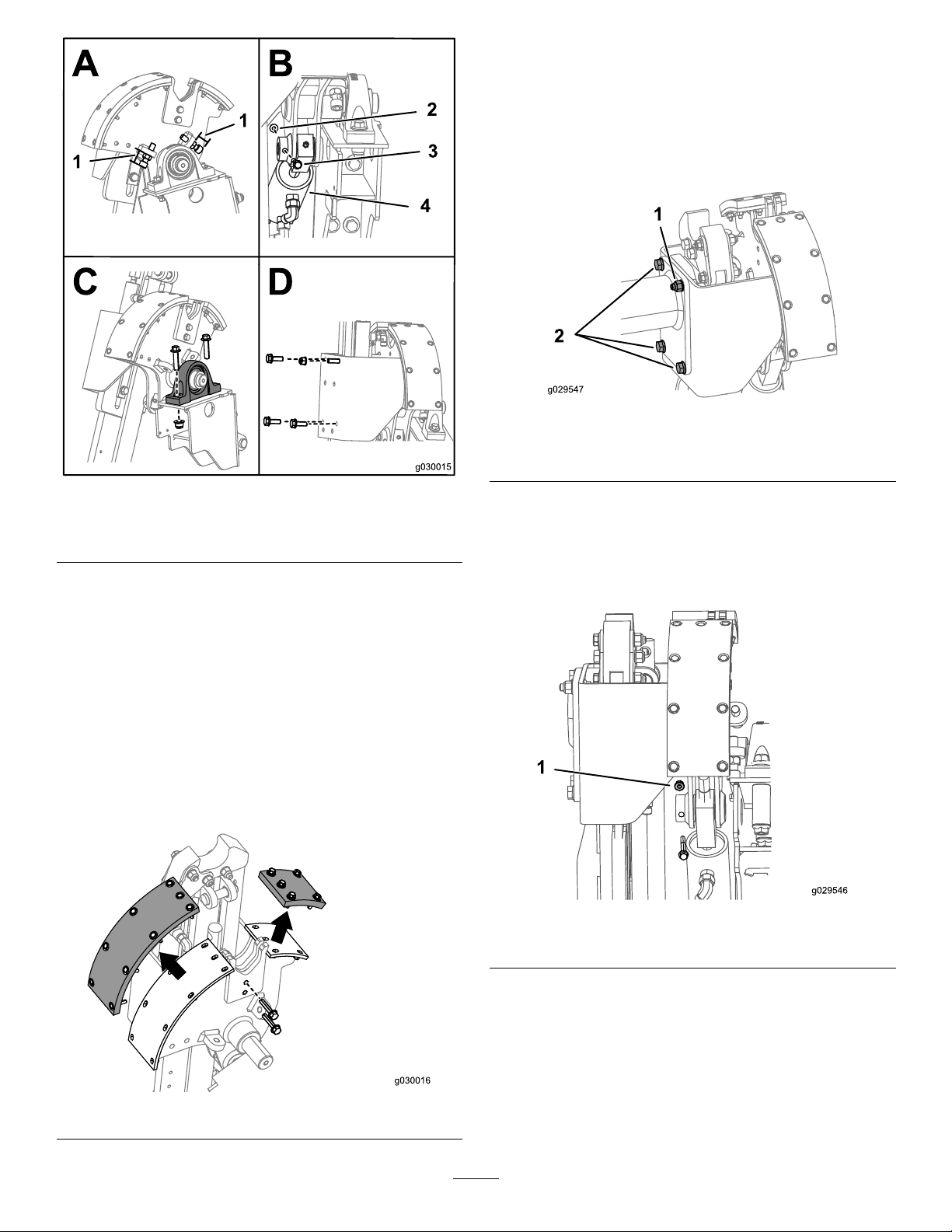
4.Measurethedistancebetweentheagandtheendof
theadjustmentboltsasshowninBoxAofFigure4.
3
Page 4
11.Assemblethenewcamassemblyusingthewearpads
andboltsfromthepreviouscamassemblyand14
angenutsand2locknuts(M8)includedinthiskit
(Figure5).
12.Installthenewcamassemblyusingthe3bolts(M10-1.5
x30mm),1bolt(M10-1.5x35mm),and1locknut
(M10)asshowninFigure6.
Figure6
Figure4
1.Measurehere3.Bolt
2.Nut4.Hydrauliccylinder
5.Disconnectthehydrauliccylinder(BoxBofFigure4).
6.Removethepillow-bearingassembly(BoxCofFigure
4).
Note:Discardthewasherbutkeeptheboltsandnuts.
7.Supporttherod-loaderassembly(Figure1).
8.Removethehardwaresecuringthecamassemblytothe
machine(BoxDofFigure4).
9.Removethecamassembly(Figure2).
10.Removethewearpadsandhardwareconnectedtothe
camassemblyasshowninFigure5.
1.Bolt(M10-1.5x35mm)
andlocknut(M10)
2.Bolts(M10-1.5x30mm)
13.Connectthehydraulicttingdisconnectedinstep3
(Figure3).
14.Installthehydrauliccylinderassemblyusingthebottom
boltfromthepreviouscamassemblyand1angenut
fromthiskitasshowninFigure7.
Figure5
Figure7
1.Flangenut
15.TorquetheM10boltsto47to57N-m(34to42ft-lb).
16.Discardthewasherthatwasremovedduringthe
removalofthecamassemblyinstep6;refertoBoxC
ofFigure4andFigure8.
4
Page 5

1.Bolt(existing)4.Spacer(existing)
1
2
3
4
g0293 51
A B
C D
5
6
7
8
2.Innersensorbracket
3.Flatwasher(new)
17.Usingathread-lockingcompoundonthebolt,install
theinnersensorbracketusingthehardwarepreviously
removedwithanewatwasherasshowninFigure8.
18.Torquetheboltto103to127N-m(78to102ft-lb).
19.Tightenthebearingsetscrew.
20.Installthenut(M10-1mm)andmagneticboltfromthe
rotarysensortotheendofthecamassemblyshaftas
showninBoxAofFigure9.
Figure8
5.Nut(existing)
Figure9
1.Nut(M10-1mm)5.Bolt(M4-10mm)
2.Magneticboltfromthe
rotarysensor
3.Nut(M4-0.07mm)
4.Outerbracket8.Gapof0.12to0.24inch
21.Securetherotarysensorontotheouterbracketusing2
bolts(M4-10mm)and2nuts(M4-0.07mm)asshown
inBoxBofFigure9.
Note:Usethread-lockingcompoundontheboltsif
thelocknutsarenotnylonlocknuts.
22.Torquetheboltsto2.2to2.7N-m(19to23in-lb).
23.Securetheouterbracketandrotary-sensorassembly
ontotheinnerbracketusing2bolts(M8-1.25x20mm)
and2locknutsasshowninBoxCofFigure9.
6.Bolt(M8-1.25x20mm)
7.Locknut
24.Torquetheboltsto23to29N-m(17to21ft-lb).
25.Adjustthebracketassemblytoachieveagapof0.12to
0.24inch(BoxDofFigure9).
26.PlacethecamassemblyintheHOMEpositionand
ensurethatthemarkontheboltisalignedwiththe
wireonthesensorasshowninFigure10.
5
Page 6

Figure10
1.Markonthebolt
27.Securethesensorwiretothebracketusingacabletie
asshowninFigure11.
2.Sensorwires
2
MovingtheProximity SensorandReplacingthe Rod-LoadingAdjustment Hardware
Partsneededforthisprocedure:
2
Bolt(M8-1.25x40mm)
2
Bolt(M8-1.25x30mm)
2
Bolt(M5-0.08x25mm)
2
Nut(M5-0.08mm)
2
Bolt(M8-1.25x20mm)
Procedure
1.Measurethedistancefromtheproximitysensortothe
extensiononthemachineasshowninFigure12.
Figure11
Figure12
1.Measurethedistancehere
2.Movethefrontcamproximitysensorandbracketfrom
thefrontofthemachinetotherearcamcylinderonthe
rearofthemachineasshowninBoxAofFigure13.
6
Page 7

Figure14
Figure13
1.Proximitysensorcurrent
location
2.Nut(M5)5.Bolt(M5)
3.Bracket
4.Proxsensor
6.Bolt(M8–11/4x20mm)
3.Securetheproximitysensorbracketwiththe2bolts
(M5-0.08x25mm)and2nuts(M5-0.08mm)asshown
inBoxBofFigure13.
4.Ensurethatthedistanceisthesamemeasurementfrom
step1(Figure12).
5.Torquetheboltsto791to971N-cm(70to86in-lb);
refertoBoxCofFigure13.
1.Measurehereonboth
sidesofthemachine
2.Bolt(M8–1.25x40mm)
3.Bolt(M8–1.25x30mm)
7.Replacethetopboltswiththelongbolt(M8-1.25x40
mm)(BoxBofFigure14).
8.Replacethebottomboltswiththeshortbolt(M8-1.25
x30mm)(BoxBofFigure14).
9.Adjusttheboltstomatchthemeasurementsfromstep
6.
10.Torquethebolts(M8)to23to29N-m(17to21ft-lb).
6.Measurethedistancebetweenthethreadedadjustment
blockandthetopofthebolt,asshowninBoxA
ofFigure14,onboththefrontandbackthreaded
adjustmentblocks.
7
Page 8

3
1
2
3
g0293 55
A
B
C
InstallingtheWiringHarness
Partsneededforthisprocedure:
1Wiringharness
16
Cableties
Procedure
1.Disconnectthebattery.
Note:Disconnectthenegativeterminalrstthenthe
positiveterminal.
2.Securethejunctionofthewiringharnesstothemain
wiringharnessasshowninFigure16.
Important:Routetheharnessalongthecurrent
machinewiringharnessandhydraulichoses.
Important:Usethecabletiestosecurethenew
wiringharnesstotheexistingwiringharnessand
frameofthemachine.
3.Routetheharnessleadmarkedstarteralongthewiring
harnessofthemachinestothestarterontheengine
andattachtheringterminaltothesamelocationasthe
currentwire(BoxBofFigure17).
Important:Ensurethattheharnessdoesnot
interferewithanyhotormovingparts.
Figure15
Topviewofthemachinewiththewiringharness
Figure17
Wiringharnesswithcableties
1.(colorandnumber)3.(colorandnumber)
2.(colorandnumber)
4.RoutethewiresmarkedasControllerApins8(red
wire),9(blackwire),and14(pinkwire)towardthe
stackofcontrollersasshowninBoxCofFigure17.
Note:Thecontrollerclosesttothemountingplate
shouldbeControllerA.Installthe3wiresintothe
properlocationsasindicatedonthetag.Thewire
sideoftheconnectorshasnumbersforreferenceto
locations.Thelocationshavearedsealpluginthehole
thatyouneedtoremovebeforeyoucaninstallthewire.
Inserttheterminaluntilthecontactclicksandlocks.
Pullslightlyonthewiretomakesurethatitisproperly
locked.Turntheconnectoroverandvisuallyinspectto
ensurethatterminalislockedalltheway.
5.Routetheremainingharnesstowardthethrustframe,
followingtheexistingharnessrouting(Figure15).
Figure16
Wiringharnesswithcableties
6.RoutethewiresmarkedasSetupValveandPipeLoader
(Front)forwardfromofthemachinefollowingthe
existingharnessrouting.
Note:Youshouldendupontheoutsideofthe
machineasshowninFigure18.
8
Page 9

Figure18
Wiringharnesswithcableties
7.RoutetheconnectorsmarkedSetupValveuptothe
9-sectionvalveblocktothetopsolenoidmarkedSetup
Valve(Figure18).
8.Disconnecttheconnectorfromthetopsolenoidvalve
andplugitintothematingconnectoronthenew
harness.
Figure20
15.Installthelatestversionofsoftwareintothemachine
andcompletethetestsdescribedinthatsoftware
update.
4
9.Plugtheotherconnectorintothevalveyoupreviously
disconnected.
10.Locatetheroundconnectorontheexistingharness
thatwaspreviouslyconnectedtotheproximitysensor
(Figure18).
11.Unscrewtheconnector,removethecabletiessecuring
thiswire,andattachtheexistingconnectortothe
connectoronthenewharness(Figure18).
12.Routetheremainderofthenewharnessalongthe
existingharnessunderthethrustframe(Figure15).
13.RoutethewireswiththeRotarySensorconnector
alongthethrustframewiththeexistingharnesstoward
therearofthemachineandcontinuetoroutethe
harnessalongthehydrauliclinesasshowninFigure19.
RemovingtheRotaryPump
SupplyandDrainOrices
Partsneededforthisprocedure:
1
Gasket
RemovingtheRotaryPumpSupplyand
DrainOrices
Important:Allowtheenginetocool.
1.Placeaoilpanunderthemachinetocatchoilfrom
therotarypump.
2.Removeandplugthecasedrainlinefromtherotary
pumpandcapoffthecasedrainttingtominimize
hydraulicuidloss.
Figure19
Wiringharnesswithcableties
14.Connecttheconnectorstotheproximitysensorand
therotarysensor(Figure19).
Note:Securethewiringharnesstothemachineas
showninFigure20.
9
Page 10

1.Removethesebolts
1
2
3
g029477
Figure21
2.Capoffthecase-drainline
10.Cleanthesealingsurfacesofthepumphousingand
controlhousing.
11.Installthecontrolhousingontothepumpusingthe
newgasket.
Important:Thecontrollinkagepinonthecontrol
mustbeinsertedintotheswash-platelinkinthe
pump.
Note:Usepetroleumjellytohelpholdtheswash-plate
linkinplacewhilethecontrolisinstalled.
Important:DonotuseRTVsealant.RTVsealant
candamagethepump.
Note:Therewillberesistancewhenthefrontedge
ofthecontrolistiltedawayfromthepumphousingif
thecontrollinkagepinisinsertedintotheswash-plate
linkcorrectly.
Note:Ifthecontrollinkagepinisnotproperly
insertedintotheswash-platelink,thepumpwillnot
returntoneutralandtherotarymotorwillspinupon
enginestartup.
12.Installthe6retainingbolts;torquetheboltsto16N-m
(12lb-ft).
3.Cleantheexternalsurfaceoftherotarypump.
4.Unplugthewiringharnessfromthepumpcontrol.
5.Removethe6boltsasshowninFigure21.
6.Removethecontrolfromthepumphousing.
Note:Oilwilldrainfromthecasewhenthehousing
isremoved.
7.Useneedlenoseplierstopulltheretainingclip(T40)
fromthecontrol(Figure22).
Figure22
13.Connectthecasedrainlineandcheckthehydraulic
uidlevel;refertotheOperator’ sManualforthemachine.
14.Connectthewiringharnesstotherotarypumpcontrol.
15.Wipeupanyspilledoil.
16.Startthemachinetotesttherotarypump.
Important:Iftherotaryoutputspinswhenthe
machineisstartedbuttherotationcommandis
notgiven,thecontrollinkagepinisnotproperly
insertedintotheswash-platelink.Removeand
capthecasedrainlineandrepeattheabovesteps.
1.T50orice3.T60orice
2.T40,T30,andT20orices
8.Removethespring(T30)andsupplyorice(T20)from
thecontrol(Figure22).
9.Removethedrainorices(T50andT60)fromthe
controlhousing(Figure22).
10
Page 11

CheckingtheNeutralAdjustment
1.Installahydraulictestportanda1000psigaugeineach
ofthedisplacementcontrolports(M4andM5).
Figure23
5
InstallingtheThrustMotor Anti-RotationSupports
Partsneededforthisprocedure:
4Adjustmentblock
4Brace
8
Nut(3/8-16inch)
4
Bolt(3/8-16x11/4inch)
4
Bolt(3/8-16x1inch)
8
Spacer
8Washer
8
Bolt(M12-13/4x70mm)
1.M72port(adjustingscrew)3.M5port(displacement
controlport)
2.M90port(locknut)4.M4port(displacement
controlport)
2.Disconnecttheelectricalconnectorfromtherotary
pumpcontrol,startthemachine,andbringittohigh
idle.
3.Loosenthelocknut(M90)witha10mmand13mm
hexwrench.
4.Usinga3mmor4mminternalhexwrench,rotate
theadjustingscrew(M72)clockwiseuntilthepressure
increasesinoneofthepressuregauges.
Note:Notetheangularpositionofthewrench.
5.Rotatetheneutraladjustingscrewcounterclockwise
untilthepressureincreasesbyanequalamountonthe
othergauge.
Note:Notethepositionofthewrench.
6.Rotatetheadjustingscrew(M72)clockwisehalfthe
distancebetweenthelocationnotedinstep(4or5).
Note:Thegaugesshouldreadthesamepressure(case
pressure),indicatingthatthecontrolisinitsneutral
position.
Procedure
RefertolocationhighlightedinFigure24forthisprocedure.
Figure24
Important:Ensurethatthereisnoweldingorweld
spatteraroundthreadedholesoronthemotormount
surfaces.
Cleanoffthepaint,oil,and/orrustfromtheweldingarea.
1.Weldtheadjustmentblocktothecarriageassemblyas
showninFigure25,Figure26,Figure27,Figure28,
andFigure29.
7.Holdtheneutral-adjustingscrewstationaryandtighten
thelocknutto7N-m(62lb-in)forthe6mmscrewor
13N-m(120lb-in)forthe8mmscrew.
8.Oncetheneutralpositionisset,stoptheengine,
removethegauges,andremovethegaugeports.
9.Connecttheelectricalconnectortotherotarypump
control.
11
Page 12

Figure25
Sideview
Figure26
TopView–Rearmounts(motorsremoved)
Figure28
SideView–Frontmounts(motorsremoved)
1.Weldthefrontmotorblocks1/8inchovertheedge.
Figure29
SideView–RearMounts(Alignedwiththeedge;motors
removed)
2.Removeanddiscardtheexistingboltandwasherfrom
thethrustmotor(BoxAofFigure30).
1.Weldtheblocks3/4inchesawayfromtheedges.
Figure27
TopView–Frontmounts(motorsremoved)
1.Weldtheblocks3/4inchesawayfromtheedges.
12
Page 13

9.Torquethe8bolts(M12)to90to112N-m(67to83
ft-lb).
10.Painttheweldedarea.
6
InstallingtheProximitySwitch Bracket
Partsneededforthisprocedure:
1Bracket
1
Plateag
4
Bolt(M5-0.08x25mm)
4
Nut(M5)
2
Cabletie
Figure30
1.Brace
2.Bolt(M12)
3.Washer
4.Spacer
5.Nut(3/8-16inch)
6.Bolt(3/8-16x11/4inch)rearmotorassemblies
7.Bolt(3/8-16x1inch)frontmotorassemblies
3.Liftthethrustmotorandinstallthebracesupports
(BoxBofFigure30).
Note:Themotorbraceshouldbecenteredonthe
thrust-motorange.
Note:Loosenthettingsonthethrust-motorttings,
ifnecessary.
4.Applythread-lockingcompoundtothe8bolts(M12)
andlooselyinstallthebolts,washers,andspacersinto
thethrustmotorassembly(BoxCofFigure30).
5.Installthenutsonthebolts,applythread-locking
compoundtothe4bolts(3/8-16x11/4inch),and
installtheassemblyintotherearmotorassembly(Box
DofFigure30).
6.Installthenutsonthebolts,applythread-locking
compoundtothe4bolts(3/8-16x1inch),andinstall
theassemblyintothefrontmotorassembly(BoxEof
Figure30).
Procedure
Cleanoffthepaint,oil,and/orrustfromtheweldingarea.
1.Placethebracket3inchesawayfromtherodbox
mountingplateand13/4inchesawayfromthebottom
ofthecarriageweldmenttothetopofthebracketand
weldthebrackettothethrustframe(Figure31and
Figure32).
Figure31
1.13/4-inchgap
2.3-inchgap
3.Bracket
7.Placethemotorbracecenteredagainstthethrust
motorangeandalternatelytightentheadjustment
bolts(3/8-16)to37toN-m(27to33ft-lb).
8.Tightenthejamnutsagainsttheadjustmentblocks.
13
Page 14

Figure32
2.Weldtheplateagtothecarriageassembly57/8
inchesawayfromthespindleendofthecarriage
assemblyasshowninFigure33.
Figure33
1.57/8-inchgap2.Plateag
Figure34
Currentrouting
Figure35
Existingrearsensor
1.Existingsensor
5.Tagthesensorandwiringharnesstonotewhichpart
oftheharnessgoestowhichsensor(Figure36).
6.Disconnectthewiringharnessfromthe2proximity
switches(Figure36).
3.Painttheweldedarea.
4.Disconnectthewiringharnessontheexistingrear
sensor(Figure34)androutethewiringharnessthrough
theholesonthebracketasshowninFigure35.
Figure36
1.Pipe-breakoutsensor2.Pipe-returnsensor
14
Page 15

7.Removethe2proximitysensorsfromthemounting
plateanddiscardthehardware(Figure36).
8.Looselysecurethe2proximitysensorstothebracket
with4bolts(M5)and4nuts(M5)asshowninFigure
37.
Figure37
Figure39
1.Rearwrench3.Frontwrench
2.Centerofthewrenches
B.Adjustthepipe-breakoutproximitysensoruntil
thelightilluminates(Figure40).
1.Bolt(M5)
2.Proximitysensor5.Pipe-returnproximity
3.Nut(M5)
4.Pipe-breakoutproximity
sensor
sensor
9.RoutethewiringharnessasshowninFigure38,
andconnecttheproperconnectionstotheproper
proximitysensors.
Note:Ensurethattheharnessdoesnotinterferewith
anyhotormovingparts.
Figure38
Figure40
1.Pipe-breakoutlight2.Pipe-returnlight
C.Tightentheboltsandnutsonthesensor.
D.Torquetheboltsto791to971N-cm(70to86
in-lb).
Pipe-ReturnSensor
10.Securetheexcessamountofthewiringharnesswitha
cabletie.
11.Use2(ormore)peopletoadjusttheproximityswitches:
Important:Ensurethatthegearboxiscompletely
forwardinthecarriageweldment.
Pipe-BreakoutSensor
A.Pullthedrillpipeandleadbarbackthroughthe
pipeguideandintothewrenchesuntilthepipe
jointisinthemiddleofthewrenches(Figure39).
A.Pullthedrillpipeandleadbarthroughthepipe
guideandthroughthewrenchesuntilthefrontof
thepipeislinedupwiththefrontoftherodbox
(Figure41).
15
Page 16

Figure41
1.Rearbracket2.Frontbracket
B.Adjustthepipe-returnproximitysensoruntilthe
lightilluminates(Figure40).
C.Tightentheboltsandnutsonthesensor.
D.Torquetheboltsto791to971N-cm(70to86
in-lb).
7
InstallingtheCapsandDecal
Partsneededforthisprocedure:
1Valvecap
1Monitorcap
1Decal
Procedure
InstallthedecalasshowninFigure42.
Figure43
1.Valvecap2.Manual-overridevalve
Gentlyliftthemonitorawayfromtheconsoleusingaat
headscrewdriverinthegapsasshowninBoxAofFigure44.
Figure42
1.Decal
Removethemanualoverridevalvescrewandinstallthevalve
capasshowninFigure43.
Figure44
1.Gapsbetweenthemonitorandconsolepanel
Insertthemonitorcapintotheportonthebackofthe
monitorandinstallthemonitorbackontotheconsole(Box
BofFigure44).
Connectthepositiveterminalofthebatterythenconnect
thenegativeterminal.
16
 Loading...