

Page 1

Deck Belt Service Kit
For LX420 Tractors
Model No. 112-5880
Installation
Loose Parts
Use the chart below to verify that all parts have been shipped.
Form No. 3356-157 Rev A
Installation Instructions
Step
Belt
3
Important: R ead and under stand these instr uctions bef or e perf or ming the pr ocedur es
described. If y ou ar e not a trained and experienced ser vice and r epair technician, contact an
Authoriz ed Ser vice Dealer .
Note: Sa v e these instr uctions and refer to them when ordering re placement par ts .
Note: Deter mine the left and right sides of the mac hine from the operating position.
Belt keeper
Flange locknut
Description
Qty.
1
1
1
Install the new belt keeper and belt.
Use
Step
1
Preparing for Service
No Parts Required
Procedure
1. Mo v e the tractor to lev el g round.
2. Shut off the engine , w ait for all mo ving par ts
to stop , and remo v e the ignition k ey .
3. Diseng ag e the PTO (blade) and set the parking
brak e .
4. Lo w er the dec k to its lo w est position.
© 2006—The Toro® Company
8111 Lyndale Avenue South
Bloomington, MN 55420
Register at www.Toro.com. Original Instructions (EN)
Printed in the USA.
All Rights Reserved
Page 2
Step
2
Removing the Mower Deck
No Parts Required
Procedure
1. R emo v e the engine pulley belt k ee per retaining
screw from under the left side of the dec k
( Figure 1 ).
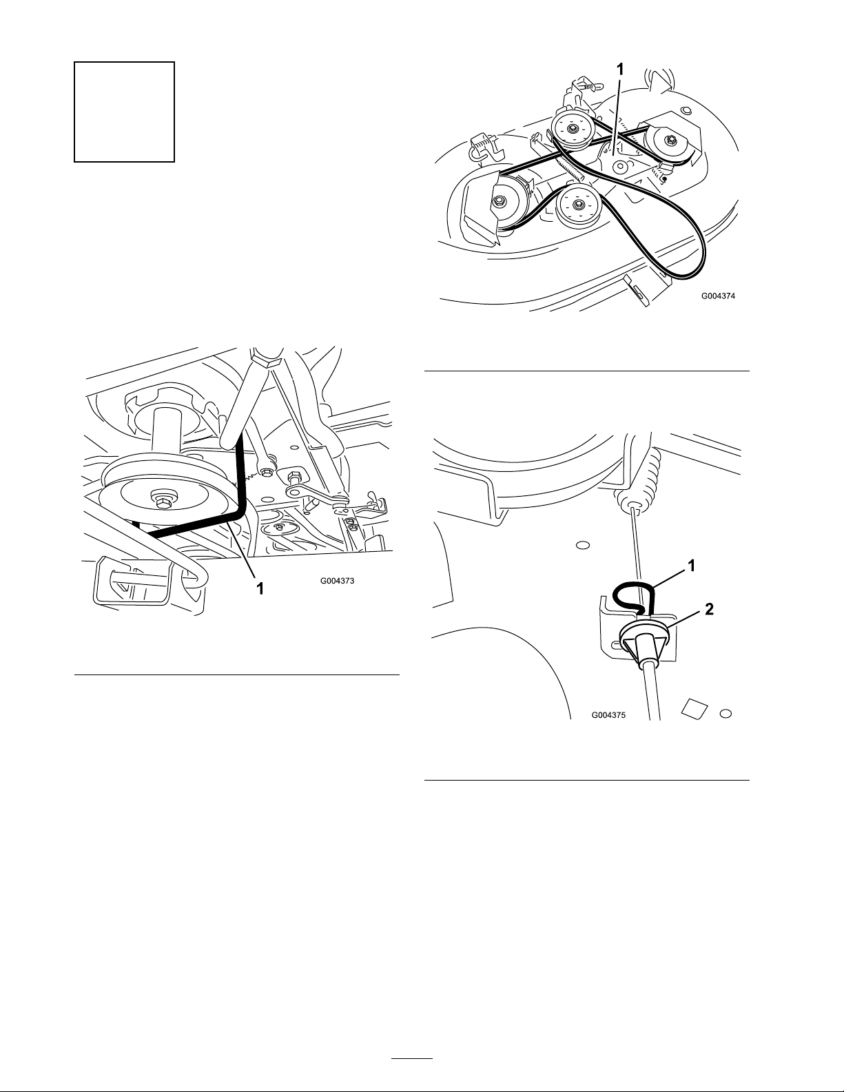
Figure 2
1. Idler bracket
4. R emo v e the hair pin clip from the PTO cable
end fitting ( Figure 3 ).
Figure 1
1. Belt keeper
Note: T he other end of the belt k ee per sets
in a hole in the right side of the frame .
Note: T ak e note of the hole the rod is in
before remo ving the belt k ee per .
2. R emo v e the belt k ee per from around the
engine pulley ( Figure 1 ).
3. Inser t a 3/8-inc h dri v e break er bar into the
3/8-inc h square hole of the idler brac k et,
reliev e the tension in the dec k dri v e belt, and
w ork the belt off the engine pulley ( Figure 2 ).
Figure 3
1. Hairpin clip 2. Cable end tting
5. Slip the cable fitting out from the cable brac k et
on the dec k.
6. Unhook the PTO cable spring from the idler
brac k et ( Figure 3 ).
7. R elease the 2 J-pins that connect the lift links
to the rear hang er brac k ets on the dec k.
8. Slide the dec k forw ard and unhook the front
hang er rod from the forw ard hang er brac k et
on the dec k.
9. Slide the dec k out from under the tractor .
2
Page 3

Step
3
Installing the New Belt
Keeper and Belt
Parts needed for this step:
1
Belt
1
Belt keeper
1
Flange locknut
Procedure
1. Locate the screw and spacer -style belt k ee per
on the tensioning idler brac k et ( Figure 4 ).
7. R etain the screw and the w asher .
8. Install the new belt k ee per onto the pulley
( Figure 5 ).
Figure 5
1. New belt keeper
Figure 4
1. Hairpin clip 2. Screw and spacer
2. Use a 3/8-inc h soc k et and ratc het to remo v e
and discard the screw and spacer ( Figure 4 ).
3. Use a 1/2-inc h soc k et and ratc het to remo v e
both belt co v ers from the left and right
spindles .
4. R emo v e the old belt and install the new belt.
Note: Ensure that the belt is cor rectly routed.
9. Discard the loc kn ut.
10. T he ring end of the new belt k ee per g oes
betw een the screw hex head and the w asher
( Figure 5 ).
Note: T he end of the belt k ee per sets in the
threaded hole v acated b y the screw and spacer
remo v ed in ste p 1 . Ensure that the new belt is
betw een the pulley and belt k ee per ( Figure 5 ).
11. Secure the idler pulley using the new flang e
loc kn ut and tighten it securely .
12. T o install the dec k, rev erse the ste ps in
R emo ving the Mo w er Dec k.
5. R e place the belt co v ers .
6. Use the 9/16-inc h soc k et and rac het and a
9/16-inc h bo x wrenc h to remo v e the screw ,
w asher , and n ut that secure the tensioning idler
pulley .
3
Page 4

 Loading...