

Page 1
IdlerSpringReplacementKit
ForLX460LawnTractors
ModelNo.112–6079
LooseParts
Usethechartbelowtoverifythatallpartshavebeenshipped.
FormNo.3360-546RevA
InstallationInstructions
ProcedureDescription
1
2
Thiskitistheupgradereplacingthe112–0432extension
springusedonthe2006ModelYear46inchcutting
deckwithmanualPTOengagement.Inaddition,thekit
includesanewbeltkeeperguide.Laterproduction46
inchcuttingdeckshavethenewspring,beltguideand
mountinghardwarethatissuppliedinthiskit.
Note:Thesematerialsarepreparedforusebytrained
technicianswhoareexperiencedintheserviceand
repairofequipmentofthekinddescribedinthis
publication,andarenotintendedforusebyuntrained
orinexperiencedindividuals.Suchindividualsshould
seektheassistanceofanauthorizedservicetechnician
ordealer.
Note:SavethisInstructionSheet.Refertoitwhen
orderingreplacementparts.
Nopartsrequired
SpringExtension(3/4ODx6.835inch)
(112–6078)
Shoulderbolt(.43x.29x5/16-18inch)
(112–0597)
Locknut(5/16inch)(112–1115)
Beltkeeperrod(112–5879)
Washer(.406x.875x.059)(112–0572)
Bolt(3/8x1-1/2inches)(1 12–0469)
1
PreparingfortheKit
Qty.
–
1
2
2
1
2
1
2.Allowengineandmufertocoolbeforeproceeding
withrepair.
3.RefertotheOperator’sManualintheServicesection
underCuttingDeckRemoval.Removethecutting
deckfromunderthetractor.
Use
2
InstallingtheKit
Partsneededforthisprocedure:
1
SpringExtension(3/4ODx6.835inch)(112–6078)
2
Shoulderbolt(.43x.29x5/16-18inch)(112–0597)
2
Locknut(5/16inch)(112–1115)
1
Beltkeeperrod(112–5879)
2
Washer(.406x.875x.059)(1 12–0572)
1
Bolt(3/8x1-1/2inches)(112–0469)
NoPartsRequired
Procedure
1.Placetractoronaatandlevelsurface,turnoffthe
engine,removetheignitionkeyandsettheparking
brakeON.
©2008—TheToro®Company
8111LyndaleAvenueSouth
Bloomington,MN55420
Registeratwww.T oro.com.
Procedure
1.Usinga1/2inchsocketandratchet,removeand
discardtheexisting112–0432extensionspringand
mountingboltsfrombothidlerbrackets.
2.Refertotheenlargedsideviewoftheinstalled
extensionspringatthebottomofFigure1.Notethe
OriginalInstructions(EN)
PrintedintheUSA.
AllRightsReserved
Page 2

orientationofthespring’shookends.Positionthe
spring,asshown,ontothelefthandidlerbracket,
112–04250.
3.Placeanewshoulderboltintothehookendand
intotheholeintheidlerbracket.Usinga1/2inch
socketandratchetanda1/2inchboxoropenend
wrench,securetothelefthandidlerbracketusinga
centerlockhexnut,item3.
4.Repeatstep6fortherighthandidlerbracket,
112–0494.
5.Ensurethatthespringiscorrectlyorientedand
installedatthecorrectidlerholessothatthespring
doesnotrubthebeltwhenthedeckisintheraised
position
6.Usinga9/16inchsocketandratchet,removeand
discardtheself-tappingbolt(3/8x1-1/4inches)
retainingtheidlerpulleyonthe112–0494idler
bracket.
7.Installthenewbeltkeeperguideusing2atwashers
andtheselftappingbolt(3/8x1-1/2inches)as
showninFigure1.
8.Thiscompletetheinstallationofthisservicekit.
9.Re-installthedeckontothetractorinthereverse
orderofremoval.
2
Page 3
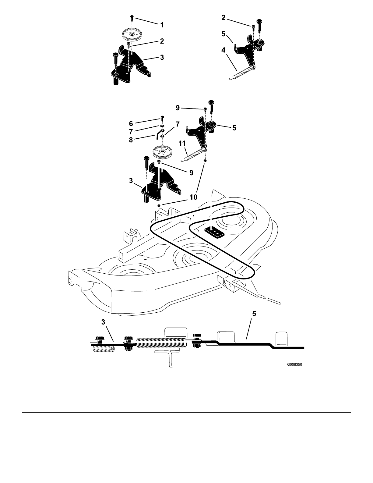
Figure1
1.Selftappingbolt4.Spring
2.Removemountingbolt5.Idler8.Beltkeeper,112–587911.Newspring,112–6078
3.Idler6.Bolt,112–0469
7.Washer,112–057210.Nut,112–1115
9.Shoulderbolt,112–0597
3
Page 4

 Loading...