

Page 1
WARRANTY..... Top Flite
®
Models guarantees this kit to be free from
defects in both material and workmanship at the date of purchase. This
warranty does not cover any component parts damaged by use or
modification. In no case shall Top Flite’s liability exceed the original cost of
the purchased kit. Further, Top Flite reser ves the right to change or modify
this warranty without notice. In that Top Flite has no control over the final
assembly or material used for final assembly, no liability shall be assumed
nor accepted for any damage resulting from the use by the user of the final
user-assembled product. By the act of using the user-assembled product,
the user accepts all resulting liability.
If the buyers are not prepared to accept the liability associated with the use
of this product, they are advised to return this kit immediately in new and
unused condition to the place of purchase.
Top Flite Models
3002 N. Apollo Dr., Suite 1
Champaign, IL 61822
Technical Assistance - Call (217) 398-8970
READ THROUGH THESE INSTRUCTIONS FIRST. THEY CONTAIN
IMPORTANT INSTRUCTIONS CONCERNING THE ASSEMBLY OF
THIS MODEL.
Congratulations for deciding to install a fully detailed, scale looking interior in your Top Flite Stinson SR9.This is a project that can be
as detailed or as simple as you care to make it – the choice is yours.We have provided the basic kit that can be assembled and painted
in a few hours.It represents a stock interior as delivered from the factory .The color scheme and minor surface details change from plane
to plane, so you may need to add extra goodies depending on the full-scale plane you modeled.By using this kit, some imagination and
your modeling experience, you can create a great looking interior that will “wow” them at the flying field.
SCALE INTERIOR KIT FOR THE GOLD EDITION STINSON SR9
TOOLS AND SUPPLIES
❏ 4oz. Aliphatic resin glue
❏ 1 oz. Thin CA (GPMR6002)
❏ Hobby knife and #11 blades
❏ Curved tip canopy scissors (HCAR0667)
❏ 220, 320 and 400-grit Wet-or-dry sandpaper
❏ Bar Sander (GPMR6170)
❏ Selection of small paint brushes
❏ Model enamel paint (Testors)
LEFTOVERS FROM AROUND
YOUR W ORKSHOP
❏ Chrome trim tape – for seat belt buckles
❏ 1/4" balsa to raise the front seats to the
proper height
❏ Thin colored vinyl material to line the
interior of the doors and the floor (optional)
PARTS INCLUDED
STNGCIPL01 ..........(2) Front seats
STNGCIPL02 ..........(1) Rear seats
STNGCIPL03 ..........(1) Steer ing wheels (sheet of two)
STNGCIPL04 ..........(1) Instr ument gauge lens
SCRW024 ...............(2) #2 x 3/8" Sheet metal screw
TAPE002 .................(2) Black elastic tape
PIN001 ....................(3) #17 White head pin
PIN002 ....................(3) #28 White head pin
DOWEL004.............(2) 1/4" x 1" Wood dowel
BN40F05.................(1) Cockpit coaming
STNGCIIP ...............(1) Laser-cut instr ument panel
™
Page 2
2
ASSEMBLE THE SEATS:
❏❏1.Cut the front seat bottom and back on the embossed cut line.
❏❏2.The front seat consists of the bottom, back and vinyl tubing for
the seat back.Tr im the seat back as needed to get a good fit between
the back and bottom.
❏❏3. Hold the seat back and bottom together with masking tape. Be
sure the back is in the recess in the back of the seat bottom.The seat
back should angle toward the rear of the cabin a few degrees.Glue the
seat back in position by “wicking” a few drops of thin CA into the joint
along the bottom and sides. Remove the tape after the CA has cured.
❏❏4. From the 36" slit vinyl tube, cut off a 13" piece and fit it around
the edge of the seat back.“Wick” some thin CA into the slit to attach the
tube to the back.
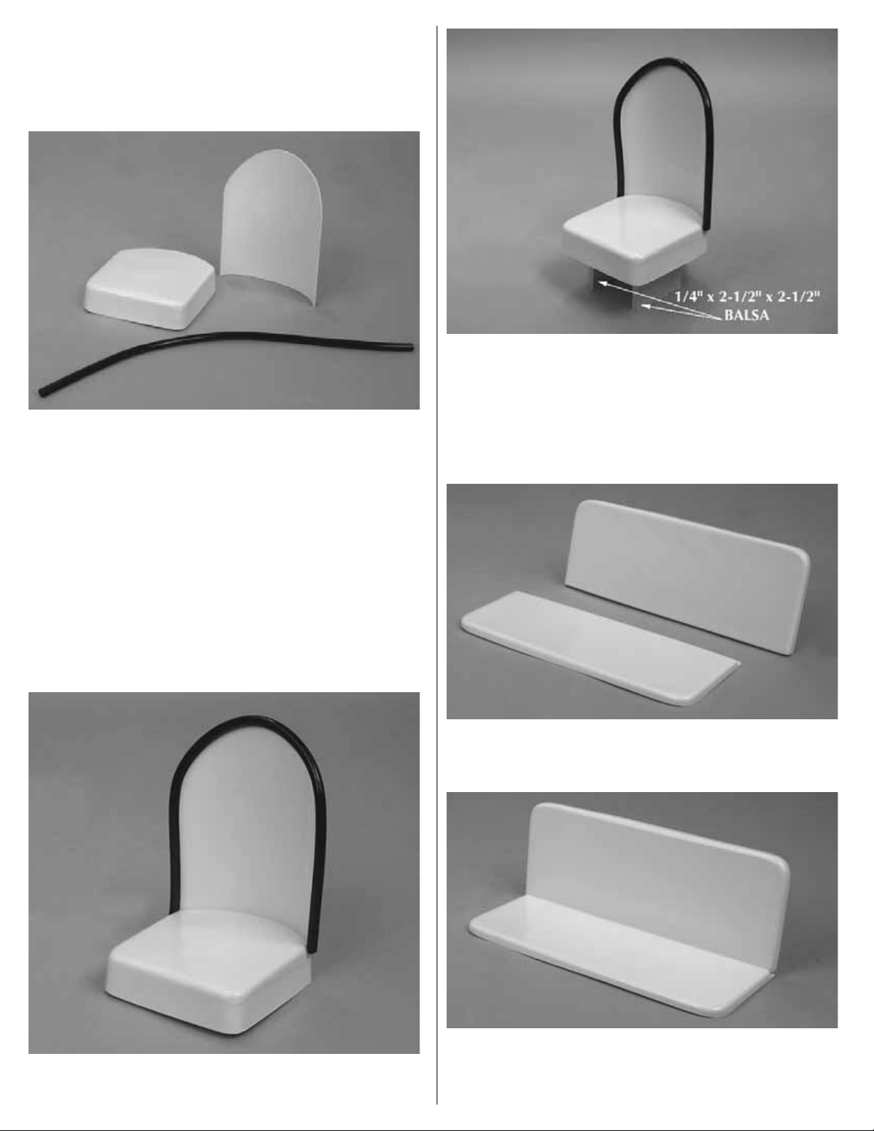
❏❏5. Make pedestals from 1/4" balsa (not included). Cut two pieces
2-1/2" x 2-1/2" and glue them to the underside of the seat.This will raise
the seats to the proper height.You may wish to add some leftover balsa to
the front and back of the pedestal.This will close off the bottom of the seat
as is shown on the cover photo of these instructions.This is optional.
❏ 6. Assemble the remaining front seat the same way.
❏ 7.Cut the rear seat bottom and back on the embossed cut line.T rim the
seat back as needed to get a good fit between the back and bottom.
❏ 8.The seat bottom is identified by the notch in the rear of the seat. Hold
the seat back to the seat bottom with masking tape.The seat back should
angle toward the rear of the cabin a few degrees. Glue the seat back in
position by “wicking”a few drops of thin CA into the joint along the bottom
and sides. Remove the tape after the CA has cured.
Page 3

PAINTING:
❏ 1. Before painting, thoroughly clean the parts with rubbing alcohol,
then allow them to dry completely.
❏ 2. Paint all the parts with model enamel (DO NOT USE TOP FLITE
LUSTREKOTE
®
PAINT). Use a 1/2" wide camel hair brush (or an artist’s
airbrush) to obtain the smoothest finish.You may wish to leav e the vin yl
around the seat back unpainted (this is a nice contrast to the color of
the seats). If you wish to paint it, we suggest you lightly scuff the
surface with some 400-grit sandpaper before painting. The balsa
pedestals should be painted flat black.
DETAILING INSTRUCTIONS:
❏ 1. Lightly sand the laser-cut plywood instrument panel. The panel
can either be painted or stained and varnished.We chose to stain ours
since most of the original aircraft had a wooden panel.
❏ 2.After applying your choice of finish, trim the clear acetate sheet to
fit the back of the instrument panel, then glue it in place.
❏ 3.Cut out the paper instrument panel from this instruction sheet.Cut off
the radio and the toggle switch portion from the sheet. Using aliphatic
glue, apply the radio and switches to the front of the instrument panel.
Glue the remaining instruments to the backside of the panel.
❏ 4. Cut out the two control yokes. Glue a 1/4" x 1" wooden dowel to
the center of each yoke and paint the assembly to the color of your
choice. When that has dried, glue the yokes in position on the
instrument panel.
❏ 5. Knobs and buttons can be made from large and small quilter’s pins
(included in this kit). Insert them through the instrument panel, then bend
them 90 degrees on the backside.Cut off the excess wire close to where
the pins are bent, then glue them in position on the backside.
❏ 6. Seat belts are cut from 1/4" dressmakers’ elastic (included in this
kit). One end is glued to the seat bottom where the seat bottom and
back come together.The other can be glued in place near the front of
the seat. Some of the Stinson SR9 versions had seating for three
people on the rear bench.Others had seating for two .We have provided
enough material for the two front seats and up to three belts for the rear
bench seat.The buckles can be cut from chrome tape or could be made
from aluminum foil.
❏ 7. In our prototype we lined the floor and the interior walls with a very
thin black vinyl (not included) that was readily available at a fabric shop.
This gave our cabin a nice finished look.You may want to consider this
as well or at the very least, paint all of the wood areas inside of the cabin.
Many more details can be added.It's up to you. A little imagination and
craftsmanship is all it takes. Have fun with this project. The results will
be well worth the effort.
FINAL INSTALLATION:
❏ 1. To make clearance for the instrument panel, cut the Top Deck of
the fuselage on the embossed lines.This will allow the instrument panel
to fit onto the bulkhead F2T. It is recommended that you paint bulkhead
F2T flat black before gluing the panel in place.
❏ 2.Glue the seats to the floor with CA. If you have painted the floor be
sure to scrape some of the paint from the wood to insure a good bond.
If you have lined the floor with vinyl it would probably be a good idea to
cut away some of the vinyl so that the bottom of the seat pedestal is in
contact with the wood floor.
❏ 3. In the instruction manual of the airplane you were instructed to
glue two pieces of leftover 1/4" x 1" x 2" balsa across the servo rails.
These are to support the rear seat and give you a point to screw the
seat in place. If you have not installed these balsa pieces, go back and
do this now.
❏ 4.Place the rear seat in position onto the balsa supports.Drill a 1/16"
hole through the seat into the 1/4" balsa supports. Remove the seat
and saturate the hole you just drilled in the balsa with thin CA.After the
glue has cured you can screw the seat in place with two #2 x 3/8" sheet
metal screws.You may wish to glue a strip of balsa to the front of the
rear seat as shown in the exploded view drawing.This will allow you to
completely hide the servos from view in the cabin.The rear seat should
be positioned over the servos and attached to the mounting rails with
two #2 x 3/8" sheet metal screws (included). Refer to the construction
manual and plan for the exact location.
When you take your Stinson to the field, be ready for the praise you
will undoubtedly receive. It is a beautiful aircraft. Happy flying!
3
Page 4

STNGCIP01 Entire Contents © Copyright 2006 Printed in USA V1.1
 Loading...