

Page 1
TOPFIELD
TF 5000 CI
TF 5100 CI
User Guide
Digital Satellite Receiver
Common Interface
Page 2

Page 3

Contents
Contents iii
1 Introduction 1
1.1 Features . . . . . . . . . . . . . . . . . . . . . . . . . . . . . . . 1
1.2 Controlling the digital receiver . . . . . . . . . . . . . . . . . . 2
1.2.1 The front panel . . . . . . . . . . . . . . . . . . . . . . . 2
1.2.2 The remote control . . . . . . . . . . . . . . . . . . . . . 4
1.3 What is common interface? . . . . . . . . . . . . . . . . . . . . 5
iii
2 Setup 7
2.1 Unpacking . . . . . . . . . . . . . . . . . . . . . . . . . . . . . . 7
2.2 Safety precautions . . . . . . . . . . . . . . . . . . . . . . . . . 7
2.3 Rear panel connections . . . . . . . . . . . . . . . . . . . . . . . 9
2.4 Connecting up your digital receiver . . . . . . . . . . . . . . . 10
2.4.1 Connecting to the antenna . . . . . . . . . . . . . . . . 10
2.4.2 Connecting to your television . . . . . . . . . . . . . . 11
2.4.3 Connecting to your video cassette recorder . . . . . . . 13
2.4.4 Inserting batteries in the remote control . . . . . . . . . 13
3 Preference Settings 15
Page 4

iv CONTENTS
3.1 Language settings . . . . . . . . . . . . . . . . . . . . . . . . . . 15
3.2 Video and audio settings . . . . . . . . . . . . . . . . . . . . . . 16
3.2.1 Television standard . . . . . . . . . . . . . . . . . . . . 17
3.2.2 Color model . . . . . . . . . . . . . . . . . . . . . . . . . 17
3.2.3 Video cassette recorder . . . . . . . . . . . . . . . . . . 18
3.2.4 Television aspect ratio . . . . . . . . . . . . . . . . . . . 18
3.2.5 Sound mode . . . . . . . . . . . . . . . . . . . . . . . . 19
3.2.6 Radio frequency output . . . . . . . . . . . . . . . . . . 19
3.3 Local time setting . . . . . . . . . . . . . . . . . . . . . . . . . . 20
3.4 Parental control . . . . . . . . . . . . . . . . . . . . . . . . . . . 22
3.5 Adjusting the on-screen display . . . . . . . . . . . . . . . . . . 23
4 Service Search 25
4.1 Searching broadcasting services . . . . . . . . . . . . . . . . . . 25
4.1.1 Configuring LNB settings . . . . . . . . . . . . . . . . . 25
4.1.2 Configuring DiSEqC 1.2 settings . . . . . . . . . . . . . 28
4.1.3 Configuring USALS settings . . . . . . . . . . . . . . . 29
4.1.4 Searching services . . . . . . . . . . . . . . . . . . . . . 30
4.2 Editing the transponder list . . . . . . . . . . . . . . . . . . . . 33
4.3 Resetting to factory settings . . . . . . . . . . . . . . . . . . . . 34
4.4 Resetting to installer settings . . . . . . . . . . . . . . . . . . . 34
5 Daily Usage 36
5.1 Volume control . . . . . . . . . . . . . . . . . . . . . . . . . . . 36
5.2 Watching television . . . . . . . . . . . . . . . . . . . . . . . . . 36
5.2.1 Watching favorite services . . . . . . . . . . . . . . . . 38
5.2.2 Viewing program information . . . . . . . . . . . . . . 38
5.2.3 Selecting audio tracks . . . . . . . . . . . . . . . . . . . 39
Page 5

5.2.4 Selecting subtitle tracks . . . . . . . . . . . . . . . . . . 40
5.2.5 Viewing teletext . . . . . . . . . . . . . . . . . . . . . . 40
5.3 Viewing electronic program guide . . . . . . . . . . . . . . . . 40
5.4 Watching multifeed program . . . . . . . . . . . . . . . . . . . 42
5.5 Making timer events . . . . . . . . . . . . . . . . . . . . . . . . 42
6 Listing Services 45
6.1 Editing the service list . . . . . . . . . . . . . . . . . . . . . . . 45
6.2 Editing the favorite list . . . . . . . . . . . . . . . . . . . . . . . 47
6.3 Transferring receiver data . . . . . . . . . . . . . . . . . . . . . 48
7 Firmware Update 50
7.1 Over the air . . . . . . . . . . . . . . . . . . . . . . . . . . . . . 51
7.2 From your computer via RS-232 port . . . . . . . . . . . . . . . 51
7.3 From another digital receiver via RS-232 port . . . . . . . . . . 52
Index 54
v
Page 6

Page 7

Chapter 1
Introduction
The TF 5000CI/ TF 5100 CI digital receiver is fully compliant
with the international Digital Video Broadcasting (DVB) standard, and can receive digital broadcasts. For its operation, you
need an antenna, which must be installed appropriately.
NOTE
In general we equate a channel with a frequency. However,
unlike analog broadcasts, digital broadcasts are not all assigned to their own frequencies; instead, multiple television
and radio broadcasts are transmitted through a single frequency. The frequency in digital broadcasting is usually called
transponder. To reduce confusion, the word service is preferably used than channel as service indicates one television or
radio broadcast in this manual.
1
1.1 Features
The TF 5000CI / TF 5100 CI digital receiver has the following
features:
• Supports DiSEqC 1.0, DiSEqC 1.1, DiSEqC 1.2 and US-
Page 8

2 Introduction
ALS.
• Can store up to 5000 television and radio services.
• Has an electronic program guide that provides an overview
of program schedules for next few hours.
• You can edit the service list.
• You can make a favorite list with your favorite channels.
• You can view the information of the current television or
radio program.
• You can update the firmware of the digital receiver to
the latest version, which will be provided by the manufacturer.
1.2 Controlling the digital receiver
The digital receiver can be operated with the remote control
and the buttons on the front panel.
NOTE
When the digital receiver is off but plugged to a wall outlet,
we say that it is in standby mode; on the other hand, when
it is on, it is in operation mode. You should keep the digital
receiver plugged to a wall outlet on standby mode so as it can
run timer events at any time.
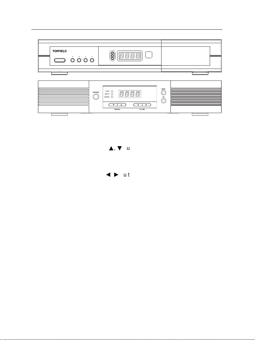
1.2.1 The front panel
The front panel of the digital receiver has buttons to operate
the digital receiver, and specific lamps and a display to indicate its status. Their usage is as follows:
Page 9
1.2 Controlling the digital receiver 3
STANDBY
CHANNEL
VOLUME
TV/STB
REMOTE
STANDBY
STANDBY button switches the digital receiver between standby
mode and operation mode. (On/Off
CHANNELa,cbuttons move to the next or previous ser-
vice. They are also used to navigate in the menus and
interactive screens.
VOLUMEb,dbuttons increase and decrease the volume.
They are also used to change options for a menu item.
TV/STB lamp lights up while your video recorder operates
instead of the digital receiver. See § 3.2.3 for more description.
REMOTE lamp lights up whenever you press a button of
the remote control.
STANDBY lamp lights up while the digital receiver is in standby
mode.
Front display displays the current time in standby mode,
and displays the current service and status of the digital receiver in operation mode.
Page 10
SAT
N/P
1
2
3
4
5
6
7
7
8
8
9
10
11
12
13
14
15
16
17
18
19
20
21
22
23
24
4 Introduction
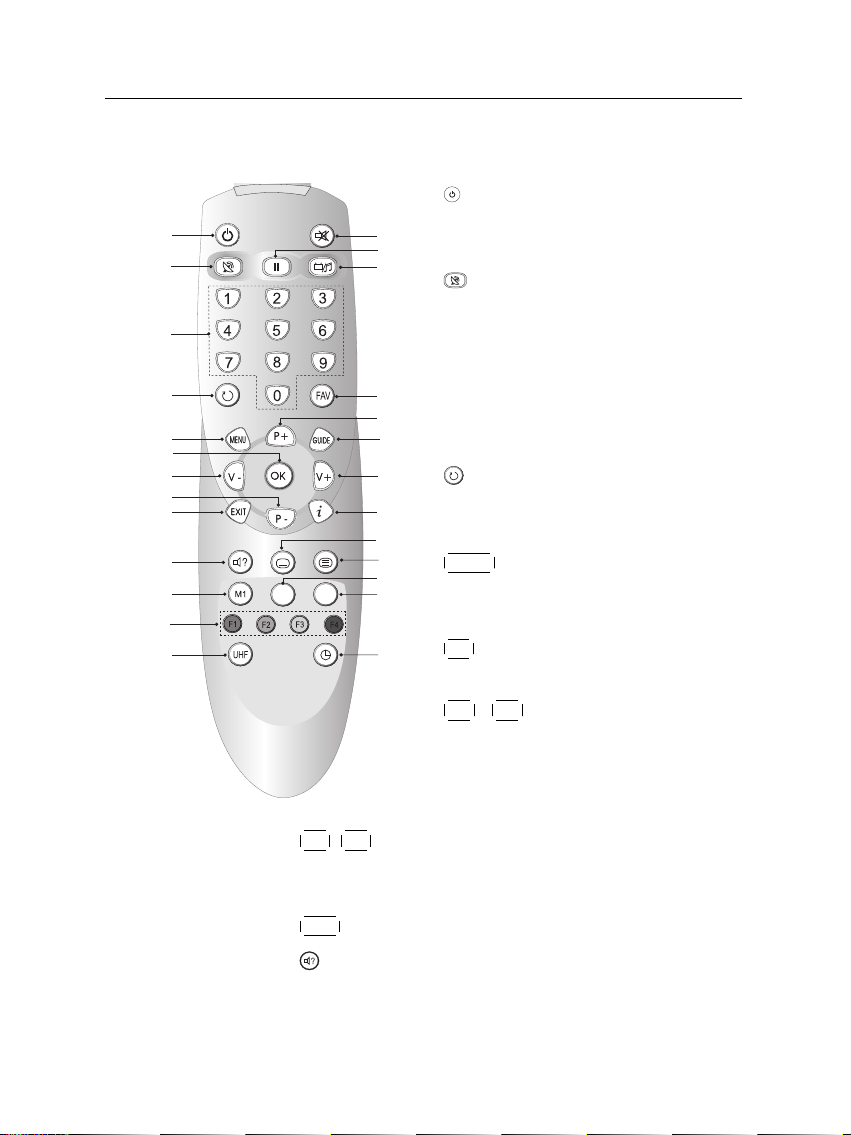
1.2.2 The remote control
1
button switches the digital receiver
between standby mode and operation
mode. (On/Off
2
button switches the output of the
TV SCART socket between the digital
receiver and the device connected to
the VCR SCART socket. See § 3.2.3 for
more description.
3
Numeric buttons are used to enter service numbers and menu options.
4
button switches between the current service and the previously viewed
one.
5
8
P+ ,
P− buttons move to the next or previous service.
They are also used to navigate in the menus and interactive screens.
9
EXIT button is used to leave the current screen.
10
button is used to select an audio track and sound
mode, or a video track of multifeed program.
6
7
MENU button displays the main menu.
It is also used to return to the previous
menu from a submenu.
OK button displays the service list. It
is also used to select menu items.
V+ ,
V− buttons increase and de-
crease the volume. They are also used
to change options for a menu item.
Page 11

1.3 What is common interface? 5
11
M1 button is not used in this model.
12
These buttons have different functions per menu. They
will be guided by on-screen help.
13
UHF button displays the RF setting menu. See § 3.2.6 for
more description.
14
mutes the sound. Press again to switch it back on.
15
button pauses live television.
16
button switches between television services and ra-
dio services.
17
FAV button displays the favorite list.
18
19
GUIDE button displays the electronic program guide. (EPG)
button displays more information about the current
program or a program highlighted in the electronic program guide.
20
button is used to select a subtitle track.
21
button displays teletext.
22
SAT button displays the satellite list with their service
list.
23
N/P button switches television standard between PAL
and NTSC. However, this button may be not used in
some models. See § 3.2.1 for more description.
24
button sets a sleep timer.
1.3 What is common interface?
Some broadcasts are scrambled so that only paid subscribers
can enjoy them. Scrambled services can only be viewed with
a Conditional Access Module (CAM) and a subscription card
belonging with the scrambling system.
Page 12
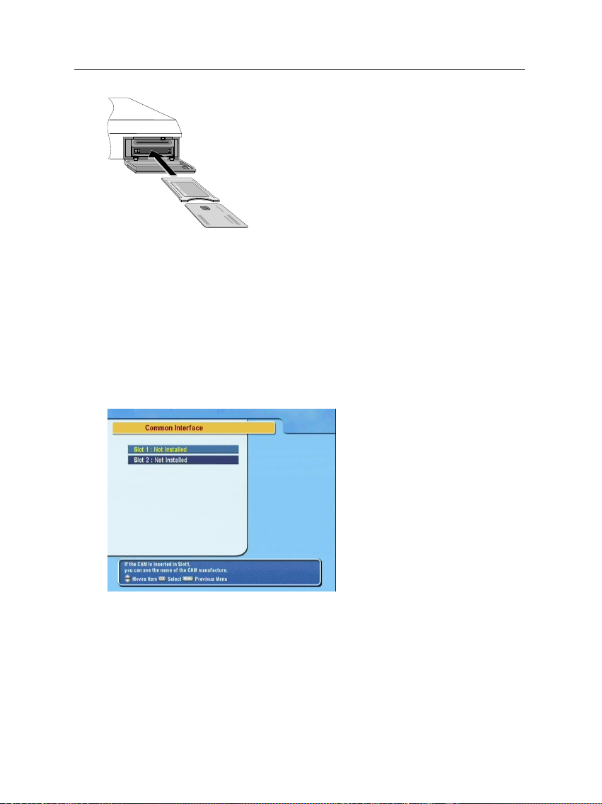
6 Introduction
Common Interface (CI) is an interface for conditional access modules. The front of the digital
receiver has two common interface slots.
To watch a pay service, you should take the following steps:
1. Purchase a conditional access module and a subscription card for the pay service you want to watch.
2. Insert the subscription card into the conditional access
module.
3. insert the conditional access module to a common interface slot on the front of the digital receiver.
To view the information about
the module and subscription
card inserted to the digital receiver, select the Common Inter-
face menu.
Page 13

2.1 Unpacking
7
Chapter 2
Setup
Before going any further, check that you have received the following items with your digital receiver.
• Remote control unit
• Two batteries for the remote control (AAA 1.5 V)
• User manual
2.2 Safety precautions
Please read the following safety precautions carefully.
• The mains power must be 90 to 250 volt. Check it before
connecting the digital receiver to the wall outlet. For the
power consumption of the digital receiver, refer to Table 2.1.
• The wall outlet should be near the equipment. Do not
run an extention lead to the unit.
Page 14

8 Setup
• Do not expose the digital receiver to any moisture. The
digital receiver is designed for use indoors only. Use dry
cloth when cleaning the digital receiver.
• Place the digital receiver on a firm and level surface.
• Do not place the digital receiver close to heat emitting
units or in direct sunlight, as this will impair cooling.
Do not lay any objects such as magazines on the digital receiver. When placed in a cabinet, make sure there
is a minimum space of 10 centimeter around it. For the
physical specification of the digital receiver, refer to Table 2.2.
• Protect the power cord from being walked on or pinched.
If wires are exposed or cord is damaged, do not use the
receiver and get cord replaced.
• Never open the digital receiver casing under any circumstances. Warranty will be void.
• Refer all servicing to an electronics qualified service technician.
Table 2.1: Power specification
Input voltage 90 to 250 V AC, 50/60 Hz
Power consumption 28 W at maximum in operation
9 W in standby
Table 2.2: Physical specification
Size 340× 60× 265 mm
Weight 2.4 kg
Operating temperature 0 to 45 °C
Storage relative humidity 5 to 95 %
Page 15
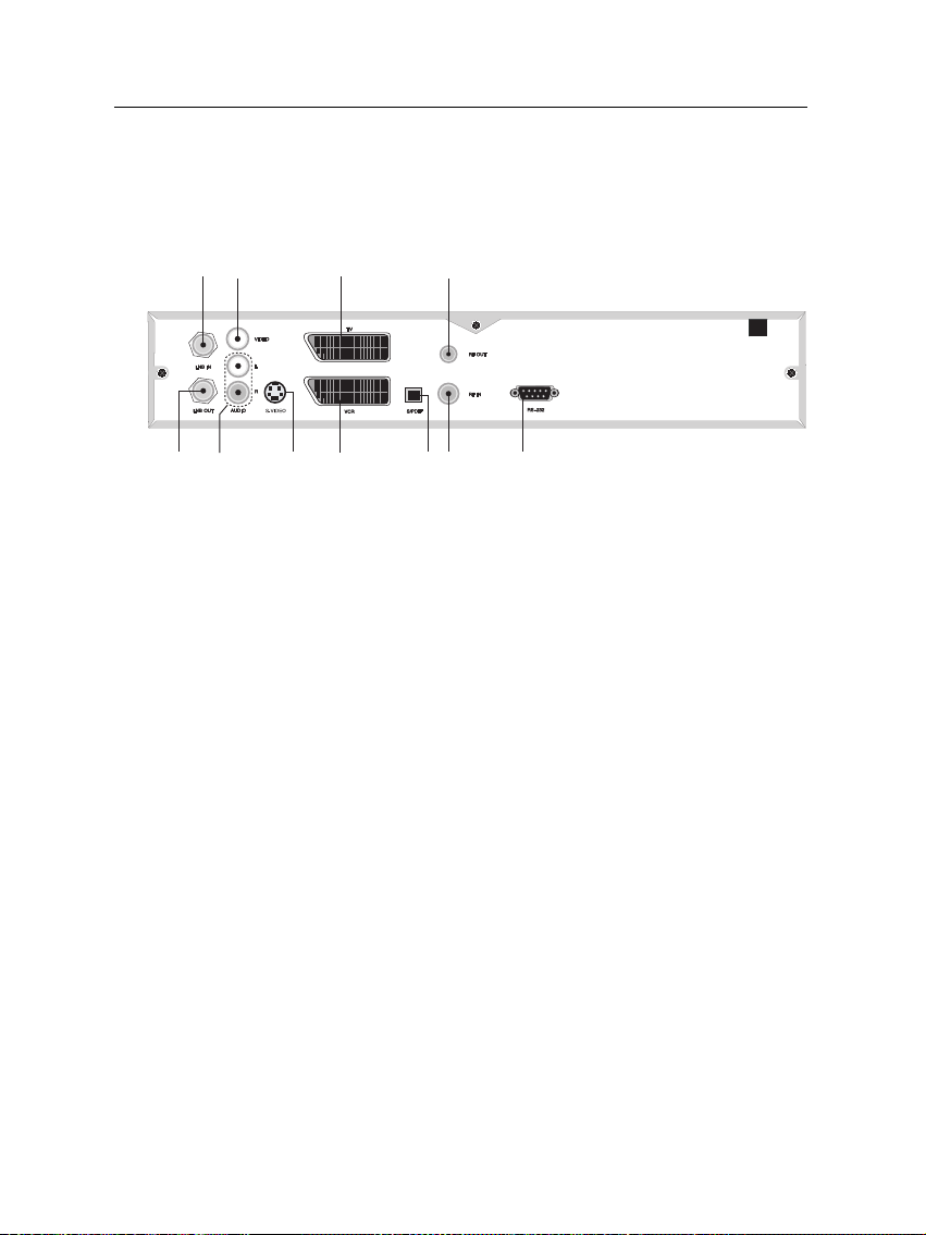
2.3 Rear panel connections
123
4
5
6
7 8 9
10
11
The TF 5000CI / TF 5100 CI has some connections on the back
panel.
Check up what connections your television set has in comparison with the digital receiver.
1
LNB IN Broadcasting input socket
2
LNB OUT Broadcasting output socket through the LNB
3
VIDEO Composite video output socket for the tele-
2.3 Rear panel connections 9
IN socket for another digital receiver.
vision set (Yellow)
4
AUDIO L/R Stereo audio output socket for the television
set or audio system. (Red/White)
5
TV Audio and video output socket for the tele-
vision set.
6
VCR Audio and video input / output socket for
the video cassette recorder or suchlike.
7
S-VIDEO Super video output socket for the television
set.
8
S/PDIF Dolby digital output socket for the audio sys-
tem.
9
RF IN Analog television input socket.
Page 16

10 Setup
10
RF OUT Analog television output socket.
11
RS-232 Serial port for firmware update and data trans-
fer.
Table 2.3: Connectors specification
VIDEO Composite video (CVBS) output
AUDIO Left & right audio output
S-VIDEO Super video (S-Video) output
TV CVBS/S-Video/RGB/YUV video output
Left & right audio output
VCR CVBS video output
Left & right audio output
CVBS/S-Video/RGB/YUV video input for bypass
Left & right audio input for bypass
S/PDIF Dolby digital audio output
RS-232 115.2 kbps at maximum
2.4 Connecting up your digital receiver
There are several ways to set up the digital receiver. Set up
the digital receiver suitably to your television and other appliances. If you have any problem with your setup or need help,
contact your dealer.
2.4.1 Connecting to the antenna
Whatever sort of connection you have between the digital receiver and the television, you need to connect the digital receiver to your television antenna so that it can receive digital
television services.
Page 17
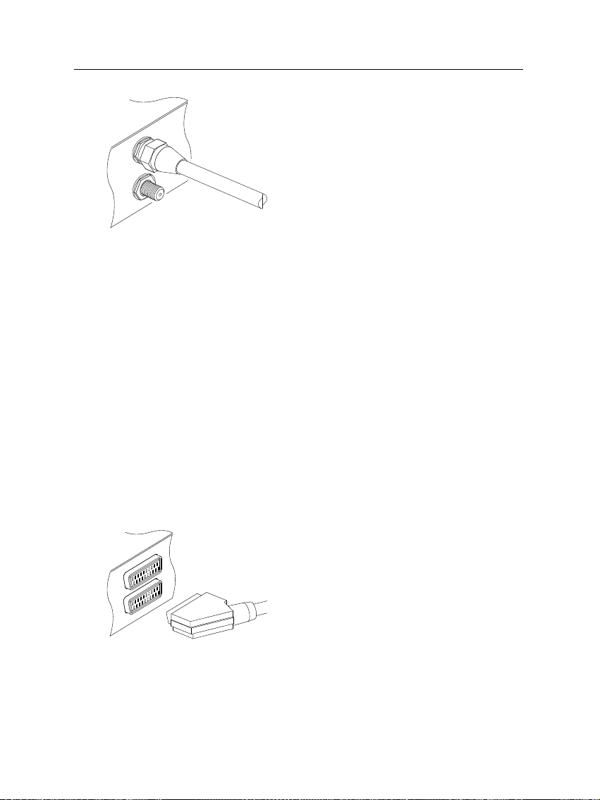
Connect the antenna cable to the LNB IN
socket.
If you have another digital receiver, link it
from the LNB OUT connector.
2.4.2 Connecting to your television
Between all the following connectors of your digital receiver,
we recommend you use the first connector to get best picture
quality. If your television does not have the matching connector then use the next connector in the following order for best
picture quality.
1. SCART connector (TV)
2. Composite connector (VIDEO)
3. RF connector (RF OUT)
You should configure audio and video settings after connecting up the digital receiver. See § 3.2 for detailed description.
2.4 Connecting up your digital receiver 11
To use the SCART connector
Some televisions have inputs via Component or S-Video connectors rather than SCART. If you have such a television, use
an appropriate conversion cable to link the TV socket on the
digital receiver to the matching socket on your television.
For best results with a standard television
set, you should use a SCART cable, plugging
one end into the TV socket on the digital receiver and the other end into a free SCART
socket on your television.
Page 18
12 Setup
If you connect with a standard SCART cable, you do not have
to make audio connections because the SCART connector can
output stereo audio. But if you do with a conversion cable,
such as SCART-to-Component, you have to make audio connections.
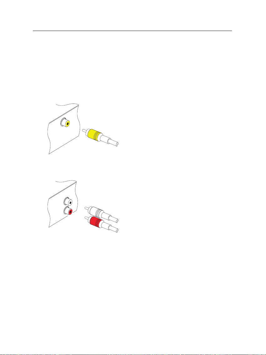
To use the composite video connector
To connect the audio connectors
You will need to obtain a composite video
cable (RCA cable) to use the composite video
connector. Plug one end of the cable into
the VIDEO (yellow) socket on the digital receiver, and the other end into the matching
socket on your television.
You will need to obtain an audio cable (RCA
cable) to connect the audio connectors. Plug
one ends of the cable into the AUDIO L
(white) and AUDIO R (red) sockets on the
digital receiver, and the other ends into the
matching sockets on your television or audio system.
To use the RF connector
If your television does not have any video and audio input,
you will need to use the radio frequency output from the digital receiver.
Page 19
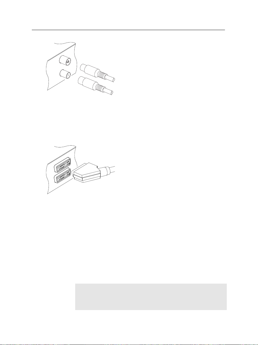
2.4 Connecting up your digital receiver 13
In this case, you will need to connect a cable from the RF OUT socket to the antenna
connector on your television. To ensure your
television can also pick up existing analogue
channels as well, you will need to connect a
cable from your television antenna to RF IN
connector.
2.4.3 Connecting to your video cassette recorder
The digital receiver also can output video to another appliance
such as video cassette recorder or video receiver through an
auxiliary SCART connector.
You will need to obtain a SCART cable to
use the auxiliary SCART connector. Plug
one end of the cable into the VCR socket on
the digital receiver, and the other end into
the matching socket on your video cassette
recorder or suchlike.
2.4.4 Inserting batteries in the remote control
To insert the batteries, open the battery compartment by removing the lid, and then insert the batteries observing the polarity, which is marked on the base of the battery compartment.
If the digital receiver no longer reacts properly to remote control commands, the batteries may be flat. Be sure to remove
used batteries. The manufacturer accepts no liability for damage resulting from leaking batteries.
NOTE
Batteries, including those which contain no heavy metals, may
not be disposed of with household waste. Please dispose of
Page 20

14 Setup
used batteries in an environmentally sound manner. Find out
about the legal regulations which apply in your area.
Page 21

3.1 Language settings
You can designate languages for menus, audio tracks and subtitle tracks.
15
Chapter 3
Preference Settings
Select the System Setting >
Language Setting menu.
Menu language
The digital receiver supports a lot of menu languages: Dutch,
English, German, French, Italian, Russian, Turkish and so forth.
Set the Menu Language option to your choice. Once you se-
Page 22

16 Preference Settings
lect a language, the menu will be immediately displayed in
the selected language.
Subtitle language
Set the Subtitle Language option to your choice. When you
watch a program, the subtitle track of the selected language
will be output if available.
Apart from this setting, you can select a subtitle track with the
button. See § 5.2.4 for detailed description.
Audio language
Set the Audio Language option to your choice. When you
watch a program, the audio track of the selected language will
be output if available.
Apart from this setting, you can select an audio track with the
button. See § 5.2.3 for detailed description.
3.2 Video and audio settings
You have to configure the video and audio settings appropriately to your television set and appliances.
To configure the video and audio settings, select the System
Setting > A/V Output Setting
menu.
Page 23

3.2.1 Television standard
The digital receiver supports two types of television standard.
One is the PAL standard, and the other is the NTSC standard. PAL was adopted in European countries while NTSC
is adopted in USA, Canada, Mexico and so forth.
If you have a PAL television, you have to set the TV Type op-
tion to PAL. In this case, if a service is broadcasted in NTSC
standard, the digital receiver converts it into the PAL standard
for your PAL television. However, its quality would somewhat fall. The opposite case brings about the same result.
The best thing is to watch PAL services with a PAL television
and to watch NTSC services with a NTSC television. However, the multi television set is able to process both of them.
So if you have an multi television set, set the TV Type option to Multi. With this option, the digital receiver will output
them without standard conversion. This setting is most recommended especially if you are not sure what standard television you have.
3.2.2 Color model
3.2 Video and audio settings 17
Through the TV SCART connector, the digital receiver is able
to output video in various color models. If you have the digital receiver linked to your television from this connector, you
should set the Video Output option to your desired color model.
If you have connected them by RCA connector at which VIDEO
reads on the back panel of the digital receiver, you do not have
to set this option because the digital receiver outputs CVBS
video through RCA connector independent of SCART connector.
It is known in general that the RGB color model provides the
best video quality with little difference from the YUV color
model but the CVBS color model does the least. So RGB would
be most desirable for this option.
Page 24

18 Preference Settings
3.2.3 Video cassette recorder
You would have the digital receiver linked to your video cassette recorder or such an appliance from the VCR SCART. The
digital receiver will operate differently depending on the setting of the VCR Scart Type option. If the option is set to Stan-
dard, the digital receiver will pass the video from the video
recorder to your television when the video recorder starts playback. But if the option is set to External A/V, the digital receiver will not pass the video even though the video recorder
starts playback. To pass it, you have to press button.
3.2.4 Television aspect ratio
If you have a wide-screen television, set the TV Aspect Ratio
option to 16:9.
You can enjoy well both wide-screen programs and normalscreen programs with your wide-screen television as the above
figures show. The left figure shows a wide picture displayed
in the wide screen, and the right figure shows a normal picture
displayed in the wide screen.
If you have a normal-screen television, set the TV Aspect Ratio
option to 4:3.
Page 25

You cannot fully enjoy wide-screen programs with your normalscreen television as the above figures show. The left figure
shows a normal picture displayed in the normal screen. To
watch wide-screen programs in the shape like the center figure, set the 16:9 Display Format option to Letter Box. Wide-
screen pictures then will be reduced to fit to the width of the
normal screen. Otherwise to watch them in the shape like the
right figure, set the option to Center Extract. Wide-screen pictures then will be cut out on the left and right sides equally to
fit to the width of the normal screen.
3.2.5 Sound mode
Basically, there are two audio sources as you can find two audio sockets on the back panel of the digital receiver. You can
enjoy only one source or both of them in either stereo or mono.
Set the Sound Mode option as you desire.
Apart from this setting, you can change the sound mode with
the button. See § 5.2.3 for detailed description.
3.2.6 Radio frequency output
3.2 Video and audio settings 19
If you have connected your television to the RF OUT socket,
you should configure the radio frequency output. The digital
receiver can make the analog television from the digital television and output it through the RF OUT socket.
Set the RF Output option to the television standard that your
country supports referring to Table 3.1.
Page 26

20 Preference Settings
Table 3.1: Television standards by country
Signal type Country
PAL G Australia, Austria, Cyprus, Czech Republic, Egypt, Estonia, Finland, Ger-
PAL I Hong Kong, Macao, Republic of Ireland, South Africa, United Kingdom
PAL K Czech Republic, Hungary, Poland
NTSC M Bahamas, Belgium, Bolivia, Chile, Ecuador, Fiji, Guam, Jamaica, Mexico,
many, Greece, Iceland, Iran, Israel, Italy, Kuwait, Latvia, Libya, Lithuania,
Luxembourg, Netherlands, New Zealand, Norway, Portugal, Slovakia, Slovenia, Spain, Sweden, Switzerland, Syria, Yugoslavia
Panama, Peru, United States, Venezuela
Set the RF Channel option to a channel number as you desire. You have to tune your television to the channel set to this
option to watch television.
If you have connected your analog television antenna to the
RF IN, you can watch analog broadcasts via the digital receiver.
3.3 Local time setting
You should set your local time for timer events. If you did
not set the local time right, the program time table provided
by the electronic program guide may also be distrustful. Refer
the electronic program guide to § 5.3.
Select the System Setting > Lo-
cal Time Setting menu.
Page 27

3.3 Local time setting 21
You can set the local time either as Manual or Auto using Greenwich Mean Time (GMT). However, it is recommended to use
the auto setting.
Table 3.2: Time offset table
Time offset City
GMT − 12:00 Eniwetok, Kwajalein
GMT − 11:00 Midway Island, Samoa
GMT − 10:00 Hawaii
GMT − 09:00 Alaska
GMT − 08:00 Pacific Time US, Canada
GMT − 07:00 Mountain Time US, Canada
GMT − 06:00 Central Time US, Canada, Mexico City
GMT − 05:00 Eastern Time US, Canada, Bogota, Lima
GMT − 04:00 Atlantic Time Canada, La Paz
GMT − 03:30 Newfoundland
GMT − 03:00 Brazil, Georgetown, Buenos Aries
GMT − 02:00 Mid-Atlantic
GMT − 01:00 Azores, Cape Verde Islands
GMT London, Lisbon, Casablanca
GMT + 1:00 Paris, Brussels, Copenhagen, Madrid
GMT + 2:00 South Africa, Kaliningrad
GMT + 3:00 Baghdad, Riyadh, Moscow, St. Petersburg
GMT + 3:30 Tehran
GMT + 4:00 Abu Dhabi, Muscat, Baku, Tbilisi
GMT + 4:30 Kabul
GMT + 5:00 Ekaterinburg, Islamabad, Karachi, Tashkent
GMT + 5:30 Bombay, Calcutta, Madras, New Delhi
GMT + 6:00 Almaty, Dhaka, Colombo
GMT + 7:00 Bangkok, Hanoi, Jakarta
GMT + 8:00 Beijing, Perth, Singapore, Hong Kong
GMT + 9:00 Tokyo, Seoul, Osaka, Sapporo, Yakutsk
GMT + 9:30 Adelaide, Darwin
GMT + 10:00 Eastern Australia, Guam, Vladivostok
GMT + 11:00 Magadan, Solomon Islands, New Caledonia
GMT + 12:00 Fiji, Auckland, Wellington, Kamchatka
To set the local time using the auto setting, follow these steps:
1. Set the Mode option to Auto; then the Time Offset option
becomes enabled.
2. Set the Time Offset option to the time difference between
Page 28

22 Preference Settings
3. Make sure that your local time is correctly displayed on
To set the local time yourself, set the Mode option to Man-
ual and enter your local time to the Local Time option with
the numeric buttons. The time format is day/month/year 24-
hour:minute.
NOTE
Daylight saving adds one hour to the time when On and removes one hour when Off. When setting time offset via GMT,
make sure time doesn’t include daylight saving.
3.4 Parental control
In general a television program is labeled a rating according to
the level of violence, nudity and language of its content. When
you are watching a program, you can check its program rating
on the information box. Refer the information box to § 5.2.2.
You can prevent your children from watching specific programs by specifying a basis rating.
your time zone and GMT referring to Table 3.2.
the Local Time option.
To specify a basis rating, select
the System Setting > Parental
Control menu; then you will be
asked the Personal Identification Number (PIN). The number
is initially set to ‘0000’.
If you wish to restrict 15 or above rated programs, set the Cen-
Page 29

3.5 Adjusting the on-screen display 23
sorship option to 15 (age). Setting it to No block restricts no
program; on the other hand, setting it to Total block restricts
every program.
NOTE
If a program does not have any rating information, your rating
setting will not take effect.
If anyone is trying to watch a program that is out of the basis rating, the person has to enter the personal identification
number to override.
To change the number, select the Change PIN Code menu;
then an input box appears. You have to enter a desired number twice for confirmation.
You can also restrict uses of some menus. Selecting the Access
Control menu displays a list of menus that you can lock. If the
Time Setting item is set to Locked, you have to enter the per-
sonal identification number to access the Time Setting menu.
If you enter a wrong number, you cannot use the menu. To
release a shut item, set it to Unlocked.
3.5 Adjusting the on-screen display
You can adjust the transparency level of the on-screen display.
Select the System Setting menu and set the OSD Transparency
option as you desire. Its available range is 0 to 50 percent.
You can adjust the display time of the information box. Refer
the information box to § 5.2.2. To adjust its display time, select
the System Setting menu and set the Info Box Display Time
option as you desire. Its available range is 1 to 30 seconds. If
you set this option to No Info Box, the information box will not
displayed when you switch services. However, pressing the
button displays the information box. If you set this option
to Never Hide, the information box will always be displayed.
Page 30

24 Preference Settings
You can raise or lower the position of the information box. Select the System Setting menu, and then set the Info Box Posi-
tion option as you desire. Its available range is −10 to +3 line.
The more high the value is set, the more low the information
box will be positioned.
Page 31

After connecting up the digital receiver, you will need to perform a service search.
4.1 Searching broadcasting services
This digital receiver can be operated with both fixed and motorized antenna system. You have to configure antenna settings according to your antenna system in the following order:
25
Chapter 4
Service Search
1. Configure LNB settings. (Refer to § 4.1.1.)
2. Set the position of your desired satellites if you have a
motorized antenna. You can control the antenna in DiSEqC 1.2 mode or USALS mode. Refer DiSEqC 1.2 to
§ 4.1.2, and refer USALS to § 4.1.3.
3. Perform service search.
4.1.1 Configuring LNB settings
There are in large two frequency bands for satellite broadcasts.
One is C band which ranges approximately from 4 to 6 GHz.
Page 32

26 Service Search
LNB
The other is Kuband which ranges approximately from 12 to
18 GHz.
The LNB (Low Noise Block converter)
is used to take a wide band of relatively high frequencies, amplify and
convert them to similar signals carried
at a much lower frequency, which is
called IF (Intermediate Frequency).
High frequencies from satellites are
converted into from 950 to 2150 MHz by
a LNB.
Select the Installation > LNB
Setting menu to configure the
LNB settings.
Pressing the
OK button on the Satellite Name option displays
the satellite list in alphabetic order. Select the satellite toward
which your antenna sets its face. Even if you cannot find your
desired satellite, you can add your desired satellite to the satellite list. See § 4.2 for detailed description.
The digital receiver has a database about broadcasting satellites and their transponders, containing the following information: satellite position, frequency range, symbol rate, polarization and LNB frequency corresponding to the frequency
range. So you might not have to specify the LNB Frequency
Page 33

4.1 Searching broadcasting services 27
option. However, if you have selected the Other entry at the
Satellite Name option to specify a satellite that is not in the
satellite list, you might have to make out the correct LNB frequency. The difference between a broadcasting frequency and
its LNB frequency must be within 950 to 2150 MHz. For example, if the frequency band of your desired satellite ranges from
3660 to 4118 MHz, you have to set the LNB Frequency option
to 5150 MHz.
The LNB has to be supplied with power to operate. Set the
LNB Power option to On if it does not have any other power
supply.
You had better ignore the 22 kHz option.
The digital receiver is designed to be compatible with DiSEqC
(Digital Satellite Equipment Control) switches. It is possible
to connect several antennas to one digital receiver by DiSEqC
switches. A DiSEqC 1.0 switch allows switching between up
to 4 satellite sources and a DiSEqc 1.1 switch allows switching
between up to 16 satellite sources.
Set the DiSEqC 1.0 and DiSEqC 1.1 options according to your
antenna configuration.
For example, to select the antenna connected to the A5 input in the left figure, set the DiSEqC 1.1 option to 2 of
4 and the DiSEqC 1.0 option to 1 of 4.
If you have a mini DiSEqC 1.0 switch
which has only two inputs, you should
set the DiSEqC 1.0 option to Mini A instead of 1 of 4.
Page 34

28 Service Search
4.1.2 Configuring DiSEqC 1.2 settings
Your motorized antenna will turn toward your desired satellites horizontally by DiSEqC 1.2.
When you switch to an service, if the service is
provided by a satellite other than current one,
it will take longer time than usual because the
antenna has to turn to its position.
To use DiSEqC 1.2, select the In-
stallation > Motorized DiSEqC
1.2 menu.
At first you have to set the Motorized DiSEqC 1.2 option to
Enable.
To get the correct position of your desired satellite, perform
the following steps:
1. Choose your desired satellite at the Satellite Name option.
2. Set the DiSEqC Command Mode to User.
3. Select the Goto option at the Motor Control menu. Then
the antenna will turn toward your selected satellite with
the position data that the digital receiver has.
4. If the receiving quality, which is displayed on the right
bottom on the screen, is not good, tune the antenna finely
with the options of the Movement menu. If you select
Page 35

the 2(E) movement option, the antenna will move to the
east by two degrees. At this time you had better check
the receiving quality of every transponder and choose
the best one at the Transponder (or Frequency) option.
It will be helpful to your fine tuning.
5. Finally select the Store option at the Motor Control menu
to save the tuned position when the receiving quality
has turned good.
There are more motor control options for installers, but this
manual does not describe them. If you are an installer, refer
them to the manual for the STAB rotor.
4.1.3 Configuring USALS settings
USALS (Universal Satellite Automatic Location System), also
known as DiSEqC 1.3, calculates the positions of all available
satellites from your location. Compared to DiSEqC 1.2, it is
no longer required to manually search and store every satellite position. Just by pointing to a known satellite position is
enough. This position will act as the central point. The USALS
will then calculate positions of visible satellites.
4.1 Searching broadcasting services 29
To use USALS, select the Installation > USALS Setting menu.
At first you have to set the Motorized DiSEqC 1.3 option to
Enable.
To calculate every satellite position, perform the following steps:
Page 36

30 Service Search
1. Choose your desired satellite at the Satellite Name option.
2. Input your location to the My Longitude and My Latitude
options with the
3. Input the position of your selected satellite to the Satel-
lite Angle if it is not correct.
4. Select the Goto the position option. Then the antenna
will turn toward your selected satellite calculating its
position.
5. If the receiving quality, which is displayed on the right
bottom on the screen, is not good, then tune the antenna
finely with the options of the Move menu. The changed
position is automatically saved at one. At this time you
had better check the receiving quality of every transponder and choose the best one at the Transponder (or
Frequency) option. It will be helpful to your fine tuning.
4.1.4 Searching services
V− ,
V+ and numeric buttons.
To perform service search, select the Installation > Service
Search menu.
There are four service search methods:
• Searching every service of a satellite.
• Searching every service of a transponder.
Page 37

4.1 Searching broadcasting services 31
• Searching one service of a transponder.
• Searching every service of a SMATV (Satellite Master
Antenna Television) transponder.
To search every service of a satellite, perform the following
steps:
1. Choose your desired satellite at the Satellite Name op-
tion.
2. Set the Search Mode option to Auto.
To search every service of a transponder, perform the following steps:
1. Choose your desired satellite at the Satellite Name op-
tion.
2. Set the Search Mode option to Manual.
3. Choose your desired transponder at the Frequency op-
tion or input it with the numeric buttons.
4. Input the symbol rate of your desired transponder to the
Symbol Rate option with the numeric buttons.
5. Set the Polarization option to the polarization of your de-
sired transponder.
NOTE
You could get the transponder information from a satellite
magazine or web site such as http://www.satcodx.com or
http://www.lyngsat.com.
To search one service of a transponder, perform the following
steps:
1. Choose your desired satellite at the Satellite Name op-
tion.
2. Set the Search Mode option to Advanced.
Page 38

32 Service Search
3. Choose your desired transponder at the Frequency op-
tion or input it with the numeric buttons.
4. Input the symbol rate of your desired transponder to the
Symbol Rate option with the numeric buttons.
5. Set the Polarization option to the polarization of your de-
sired transponder.
6. Specify the PIDs of your desired service at the PID menu
with the numeric buttons. PID (Packet Identifier) is a set
of numbers that identifies transport stream packets.
To search every service of a SMATV transponder, if the digital receiver is connected to a SMATV, perform the following
steps:
1. Choose your desired satellite at the Satellite Name op-
tion.
2. Set the Search Mode option to SMATV.
3. Choose your desired transponder at the Frequency op-
tion or input it with the numeric buttons.
4. Input the symbol rate of your desired transponder to the
Symbol Rate option with the numeric buttons.
5. Set the Polarization option to the polarization of your de-
sired transponder.
You can search pay services as well as free services. To search
only free services. set the FTA/Scrambled option to FTA only.
FTA means free service. To search only pay services, set it to
CAS only. CAS means pay service. To search both free services
and pay services, set it to FTA + CAS.
To start service search, select the Start Search item; then appears a list box, in which found services will be listed. Press
the
OK button to save found services when it is completed.
To stop at any time, or to exit without saving, press the
EXIT
button.
Page 39

4.2 Editing the transponder list
You can add, delete or modify satellite or transponder information.
To add a satellite entry, select the Add Satellite option. Then
the on-screen keyboard appears. Enter your desired name and
save it. For how to use the keyboard, refer to § 6.2.
To change a satellite entry’s name, select your desired entry at
the Satellite Name option and select the SAT Name Edit op-
tion. Then the on-screen keyboard appears. Change the name
as you desire and save it.
To delete a satellite entry, select your desired entry at the Satel-
lite Name option and select the Delete Satellite option; then
you are asked for confirmation. If you select Yes, it will be
deleted.
To add a transponder entry, select your desired entry at the
Satellite Name option and select the Add new TP option. Then
a transponder information box appears. Input a frequency
and its symbol rate with the numeric buttons, and specify its
polarization.
To delete a transponder entry, select your desired entry at the
Frequency option and select the Delete TP option; then you
are asked for confirmation. If you select Yes, it will be deleted.
4.2 Editing the transponder list 33
To edit the transponder list, select the Installation > SAT/TP
Edit menu.
Page 40

34 Service Search
4.3 Resetting to factory settings
The digital receiver maintains the following data:
• Satellite list
• Service list
• Favorite list
• Timer list
• Preference settings
You can reset all data of the digital receiver. If you want to reset all the data, select the Installation > Factory Setting menu,
then you are asked for confirmation. If you select Yes, service
entries, favorite entries and timer events will be all deleted,
and preference options will be reset to the manufacturer’s factory settings.
4.4 Resetting to installer settings
You can store your own data including the followings:
• Satellite list
• Service list
• Favorite list
• Preference settings
Also you can restore them at any time.
To store your data, select the Installation > System Recovery
menu and select the Store option; then the digital receiver will
ask your personal identification number. The number may be
different from yours because this function is usually permitted
only to installers. If you have entered a right number, you
will be asekd for confirmation. If you select Yes, your data
will be stored. Whenever you store your data, they are all
overwritten. Refer personal identification number to § 3.4.
To restore your data, select the Installation > System Recovery
menu and select the Recover option; then you will be asekd
Page 41

4.4 Resetting to installer settings 35
for confirmation. If you replay with yes, your data will be
restored.
Page 42

36 Daily Usage
5.1 Volume control
Use the
able level. You may need to adjust the volume on your television set too. To temporarily switch off the sound, press the
button. Press it again to restore the sound to the previous
level.
V− and
Chapter 5
Daily Usage
V+ buttons to alter the volume to a comfort-
5.2 Watching television
To change services, press the
button switches to the previously viewed service. You can
switch to your desired service by entering its service number with the numeric buttons. You can also select a service
to watch in the service list. To view the service list, press the
OK button.
P+ or
P− button. Pressing the
Page 43

5.2 Watching television 37
On the service list, you can view
the service information as follows:
• Service number
• Service name
• Transmitting satellite
• Transponder information
A dollar sign ($) may be marked on some entries, which indicates pay service. To watch pay services, you need the subscription card.
To select a desired service, put the highlight bar on its entry
with the
P+ or
P− button and press the
OK button; then it
will be presented.
Pressing the
V− or
V+ button skips over 10 entries up or
down. Entering a service number with the numeric buttons
puts the highlight bar on its entry.
Pressing the
instance, when the highlight bar is on an entry of which initial
is B, pressing the
F3 button performs an alphabetic browse. For
F3 button puts the highlight bar on the first
entry of which initial is C.
To sort the service list by service name, press the
F2 but-
ton. Pressing this button once more makes it sorted by service
number.
Pressing the
SAT button displays the satellite list. When you
select a desired satellite in the satellite list, the only services
provided by the selected satellite will be listed.
Page 44

38 Daily Usage
5.2.1 Watching favorite services
You can select a service to watch on the favorite list as well as
on the service list.
To display the favorite list, press
the
FAV button; it will be dis-
played. Whenever moving the
highlight bar on or down on
the favorite group list, favorite
services belonging to the highlighted group are listed.
To select a favorite service, put the hightlight bar on a desired
group and press the
the favorite service list. Once you select a desired service with
the
OK button, it will be presented. Otherwise, to select other
group, press the
If you switch to another service after you have selected a favorite service, it will be also another favorite service of the selected group. The digital receiver will remind you what group
you have selected displaying its name on the right top of the
screen whenever you switch services. If you wish to get out of
the current group, select the All services group on the favorite
list.
For how to edit the favorite list, refer to § 6.2.
V− button.
5.2.2 Viewing program information
Pressing button displays the information box, on which you
can see the followings:
V+ button; a highlight bar appears on
Page 45

5.2 Watching television 39
• Service number
• Service name
• Transmitting satellite
• Transponder information
• Signal level and quality
• Program name
• Program rating
• Program summary
• Broadcasting time
• Current time
In addition, you might see the following symbols:
• Subtitle symbol ( ) if subtitle tracks are provided on
the current program.
• Teletext symbol ( ) if teletext pages are provided on the
current program.
• Lock symbol ( ) if the current service is locked.
• Dollar symbol ($) if the current service is a pay service.
• Multifeed symbol ( ) if the current program is provided in multifeed service.
Pressing the button once more displays detailed information about the current program. To hide the information box,
press the
EXIT button.
5.2.3 Selecting audio tracks
Some programs are provided with audio tacks in one or more
languages. Pressing the button displays available audio
tracks. Once you select a audio track, it will be sounded. In
addition, you could enjoy audio tracks in four sound modes:
Stereo, Mono, Left or Right. However, if a multifeed program
is provided at the moment, video tracks will be displayed. In
this case, you have to press the button once more to select
Page 46

40 Daily Usage
an audio track.
5.2.4 Selecting subtitle tracks
Some programs are provided with subtitle tracks in one or
more languages. If the current program provides subtitle tracks,
the subtitle symbol ( ) will be marked on the information
box. Pressing the button displays available subtitle tracks.
Once you select a subtitle track, it will be displayed.
5.2.5 Viewing teletext
On some programs, such information as weather reports, news
or stock quotations is provided by means of teletext service.
If the current program provides teletext service, the teletext
symbol ( ) will be marked on the information box. Press the
button to view teletext pages. Select a desired page to view
by entering the page number with the numeric buttons. You
can zoom in a teletext page with the
transparency with the
press the
EXIT button.
F3 button, and adjust its
F4 button. To clear the teletext screen,
5.3 Viewing electronic program guide
The Electronic Program Guide shows the current and scheduled programs that are or will be available on each service
with a short summary for each program.
Page 47

5.3 Viewing electronic program guide 41
Pressing the
plays the electronic program
guide, on which you can see the
followings:
• Scheduled programs
• Program summary
• Broadcasting date
• Broadcasting time
GUIDE button dis-
To see detailed information of a desired program, put the highlight bar on your choice with the
button. To switch to other service, press the
button.
To see the program guide for radio broadcasts, press the
button. To turn it back, press the button again.
Pressing the
of spreadsheet. To turn it back, press the
You can make a timer event on the electronic program guide
as follows:
1. Select a service you want.
2. Press the
3. Select a program you want with the
4. To remove the marking, press the
F1 button displays the program guide in the form
GUIDE button to display its program guide.
marked up on the entry. At the same time, a timer event
with the selected program will be made in the timer list.
Refer the timer list to § 5.5.
P+ or
P− button and press
F1 button again.
OK button, then P is
OK button once again.
V− or
V+
Page 48

42 Daily Usage
5.4 Watching multifeed program
Some broadcasts such as sports channels can provide a variety
of perspectives on a program at the same time. We call it multifeed program. You can select and watch a perspective you
prefer.
In similar method, it is possible to provide multiple copies of
a program at short intervals.
Order Starting time
1 13:00 PM
2 13:15 PM
3 13:30 PM
4 13:45 PM
5 14:00 PM
If a multifeed program is provided on the current service, the
multifeed symbol ( ) will be marked on the information box.
Press the button, then available video tracks will be listed.
Once you select one, it will be presented. At this time, you
have to press the button once more to select audio tracks.
5.5 Making timer events
You can make the digital receiver to present your desired service at a specific time. Even if the digital receiver is off, it will
turn on at the specified time.
For example, assume a movie is
broadcasted at five steps like on the
left table. Even if you have missed the
movie of the first step, you can watch
one of the subsequent steps.
Page 49

5.5 Making timer events 43
To input a timer event, select the
System Setting > VCR Timer
Setting menu; then the timer list
will be displayed.
To add a new timer event, press the
F1 button; then a box like
the above figure appears.
1. If you want a radio program, set the Type option to Ra-
dio; otherwise, set it to TV.
2. Set the Satellite option to the satellite which transmits
the service you want. Pressing the
OK button on this
option displays a satellite list, from which you can select
your desired satellite.
3. Set the Service option to the service which provides the
program you want. Pressing the
OK button on this
option displays a service list, from which you can select
your desired service.
4. There are five timer modes:
One Time means literally ‘one time’.
Every Day means literally ‘every day’.
Every Weekend means ‘Saturday and Sunday per week’.
Weekly means ‘one day per week’.
Every Weekday means ‘from Monday to Friday per
week’.
If your favorite program is broadcasted at weekends and
Page 50

44 Daily Usage
you wish to watch every episode of the program, set the
Mode option to Every Weekend.
5. Set the Date option to a desire date, on which the recording will be started. The date format is day/month/year–
day of the week.
Set the Wakeup Time option to a desired time, at which
the digital receiver will turn on. You can enter it with
the numeric buttons. The time format is hour:minute.
6. Set the Duration option to a desired time, in which the
digital receiver will turn off.
7. To set a timer event with the above settings, select the
OK option; otherwise, it will not be made.
Page 51

6.1 Editing the service list
You would have got the service list after service search. You
can rename, move, lock or delete service entries on the service
list.
45
Chapter 6
Listing Services
To edit the service list, select the
Organizing Services menu; then
a screen will be displayed like
the left figure. There are editing options on the left column
and service entries on the right
column.
Once you put the highlight bar on a desired option on the left
column and press the
vice to edit on the right column. To go over to the other column, press the
OK button, you can select a desired ser-
F1 button.
Page 52

46 Listing Services
To edit the radio service list, press button; then radio service entries will be listed on the right column. To turn back to
the television service list, press it again.
To change the name of a service, select the Rename and select
a desired service; then the on-screen keyboard appears. For
how to use the keyboard, refer to § 6.2.
Unlike analog broadcasts, each service does not have a proper
service number in digital broadcasts. Service numbers are assigned to the services just in the order that they were found in
the service search. So you can reassign a service number by
moving a service entry. To move a service entry, select the
Move option and select a desired service; then the selected
service becomes darker. As you move it up or down, it gets
renumbered according the position. Press the
OK button to
fix it.
You can lock some services so as to prevent your children
from watching them. To lock a service, select the Lock option and select a desired service; then the lock symbol will
be marked on the selected service. If anyone tries to watch a
locked service, the person has to enter the personal identification number that is set to the Change PIN Code option. See
§ 3.4 for this option. To unlock a locked service, press the
OK
button on it.
To delete a service, select the Delete option and select a desired service and press the
EXIT button; then you are asked
for confirmation. If you select Yes, the selected service will
be deleted. If you want to undo the deleted service, you have
nothing to do but perform service search again.
Once you select the Sort option on the left column, sorting
options are displayed as follows:
Sort A–Z by service name
Sort CAS–FTA from pay services to free services
Sort FTA–CAS from free services to pay services
Page 53

Sort Fav–NoFav from favorite services to unfavorite services.
Sort Sat Name by satellite
6.2 Editing the favorite list
You can make your own favorite service list. To edit your
favorite list, select the Organizing Favorites menu; then an ed-
itable favorite list appears.
You can add a favorite entry by performing the following steps:
6.2 Editing the favorite list 47
There are a group list on the
left column, a favorite list on the
center column and a service list
on the right column.
1. Put the highlight bar on a desired group entry in the
group list and press the
2. Then the highlight bar of the service list becomes movable. Put the highlight bar on a desired service entry and
press the
3. Then the selected service entry is added in the favorite
list. You can select more entries to add.
4. Press the
the
in turn.
You can up to 30 groups. To add a group, select the NEW
option in the group list; then the on-screen keyboard appears.
OK button.
F1 button to select another group. By pressing
F1 button, the highlight bar of each column moves
OK button.
Page 54

48 Listing Services
You can move the highlight key horizontally
with the
with the
button on a key enters its letter in the input line.
To type a space, select the Space key. To type lower case letters
or numerals, select the Other key. To delete a letter, put the
cursor on a desired letter at the input line and then select the
Del key. You must select the Save key to complete naming;
otherwise, if you press the
To rename a group, put the highlight bar on a desired group
you wish to rename and press the
screen keyboard will appear as above.
To delete a group, put the highlight bar on a desired group you
wish to delete and press the
box appears. If you select Yes, it will be deleted.
Similarly, you can delete a favorite entry with the
in the favorite list. Besides, you can rearrange a group’s favorites by moving a favorite entry. To move a favorite entry,
put the highlight bar on a desired entry to move and press the
F2 button; then the selected entry becomes dark. Move it to a
desired place and press the
To add radio services, press button; then radio service entries will be listed in the service list. To recall the television
service list after adding radio services, press button again.
With your favorite service list, you can select your favorite services more easily. Refer to § 5.2 for more information.
V− and
P+ and
V+ buttons and vertically
EXIT button, it will not be named.
F3 button; then a confirmation
P− buttons. Pressing the
F2 button; then the on-
OK button.
OK
OK button
6.3 Transferring receiver data
The digital receiver retains such data as follows:
Page 55

6.3 Transferring receiver data 49
• Service list
• Favorite list
• Preference settings
It is possible to transfer receiver data to your digital receiver
from another same digital receiver connecting them with a RS232 cable.
To transfer receiver data, perform the following steps:
1. Plug one end of a RS-232 cable (9 pin D-
sub cable) into the RS-232 port on the
digital receiver, and the other end into
the matching port on the other digital receiver.
2. Turn on both of them.
3. Select the Installation > Transfer Data to
Other IRD menu.
4. Restart the digital receiver.
NOTE
You had better memorize some important data such as video
settings before starting transfer to avoid resetting them.
Page 56

50 Firmware Update
Chapter 7
Firmware Update
The digital receiver has a stable and convenient firmware to
use. However, a new firmware may be released to improve the
digital receiver. You can get a latest firmware and an update
utility from the Topfield web site, http://www.i-topfield.
com.
You should check the firmware
information of your digital receiver before downloading a
new firmware. To check the current information of the digital
receiver, select the Information >
IRD Status menu.
NOTE
You have to update with only the new firmware of which System ID is identical to yours. otherwise you will fail in firmware
Page 57

update.
7.1 Over the air
You can get a new firmware over the air.
7.1 Over the air 51
To update the firmware by this
method, press the Installation >
Firmware Upgrade menu.
Selecting the Start option starts
firmware update
Satellite Astra
Frequency 12603 MHz
Symbol Rate 22000 KS/s
Polarity Horizontal
PID 347
On the left table is presented
the transponder information
appointed by the manufacturer Topfield for firmware
update.
This transponder information can be changed. You can get the
information at the Topfield web site, http://www.i-topfield.
com.
7.2 From your computer via RS-232 port
It is possible to transfer a new firmware to the digital receiver
from your computer connecting them with a RS-232 cable. You
need TFD-Down, the firmware transfer utility for this, which
is available at the Topfield web site, http://www.i-topfield.
com.
Page 58

52 Firmware Update
To update the firmware with this method, perform the following steps:
1. Download a new firmware applicable to
the digital receiver from the Topfield web
site.
2. Plug one end of a RS-232 cable (9 pin Dsub cable) into the RS-232 port on the
digital receiver, and the other end into the
matching port on your computer.
3. Turn on the digital receiver.
4. Run TFD-Down.
The instruction on how to use TFD-Down is as follows:
1. Press Find button to select the new
firmware file.
2. Press Download button to start the file
transfer.
3. Press Stop button to cancel the file transfer.
4. Restart the digital receiver.
7.3 From another digital receiver via RS-232 port
It is possible to transfer a new firmware to the digital receiver
from another same digital receiver connecting them with a RS232 cable.
To update the firmware with this method, perform the following steps:
Page 59

7.3 From another digital receiver via RS-232 port 53
1. Plug one end of a RS-232 cable (9 pin Dsub cable) into the RS-232 port on the
digital receiver, and the other end into
the matching port on the other digital receiver.
2. Turn on both of them.
3. Select the Installation > Transfer Firmware
to Other IRD menu.
Page 60

54 INDEX
Index
16:9, 18
16:9 Display Format, 19
22 kHz, 27
4:3, 18
A/V Output Setting, 16
Access Control, 23
Add new TP, 33
Add Satellite, 33
Advanced, 31
Astra, 51
AUDIO L, 12
AUDIO L/R, 9
Audio Language, 16
AUDIO R, 12
Auto, 31
Button, 4
C band, 25
CAM, 5
CAS, 32
CAS only, 32
Censorship, 23
Center Extract, 19
Change PIN Code, 23
CI, 6
Common Interface, 6
Date, 44
Delete, 46
Delete Satellite, 33
Delete TP, 33
DiSEqC, 27
DiSEqC 1.0, 27
DiSEqC 1.1, 27
DiSEqC Command Mode, 28
Download, 52
Duration, 44
DVB, 1
Electronic Program Guide, 40
electronic program guide, 2
Every Day, 43
Every Weekday, 43
Every Weekend, 43
Factory Setting, 34
Find, 52
Firmware Upgrade, 51
Frequency, 29–33
FTA, 32
FTA + CAS, 32
FTA only, 32
Page 61

55
FTA/Scrambled, 32
GMT, 21
Goto, 28
Goto the position, 30
Info Box Display Time, 23
Info Box Position, 24
information box, 38
IRD Status, 50
Kuband, 26
Language Setting, 15
Letter Box, 19
LNB, 26
LNB Frequency, 26, 27
LNB IN, 9, 11
LNB OUT, 9, 11
LNB Power, 27
LNB Setting, 26
Local Time, 22
Local Time Setting, 20
Lock, 46
Manual, 31
Menu Language, 15
Mini A, 27
Mode, 21, 22, 44
mono, 19
Motor Control, 28, 29
Motorized DiSEqC 1.2, 28
Motorized DiSEqC 1.3, 29
Move, 30, 46
Movement, 28
multifeed, 42
My Latitude, 30
My Longitude, 30
NEW, 47
No block, 23
normal-screen television, 18
NTSC, 17
on-screen keyboard, 47
One Time, 43
Organizing Favorites, 47
Organizing Services, 45
OSD Transparency, 23
Other, 27
PAL, 17
Parental Control, 22
PID, 32
PID, 32
PIN, 22
Polarization, 31, 32
Radio, 43
radio service list, 46
Recover, 34
Rename, 46
RF Channel, 20
RF IN, 9, 13
RF OUT, 10, 13, 19
RF Output, 19
RS-232, 10, 49, 52, 53
S-VIDEO, 9
S/PDIF, 9
SAT Name Edit, 33
SAT/TP Edit, 33
Satellite, 43
Satellite Angle, 30
satellite list, 26, 37
Satellite Name, 26–28, 30–33
Search Mode, 31, 32
Page 62

56 INDEX
Service, 43
service list, 36
Service Search, 30
SMATV, 31
SMATV, 32
Sort, 46
Sort A–Z, 46
Sort CAS–FTA, 46
Sort Fav–NoFav, 47
Sort FTA–CAS, 46
Sort Sat Name, 47
Sound Mode, 19
Space, 48
Start, 51
Start Search, 32
stereo, 19
Stop, 52
Store, 29, 34
subtitle, 40
Subtitle Language, 16
Symbol Rate, 31, 32
System ID, 50
System Recovery, 34
System Setting, 23, 24
TV, 9, 11, 43
TV Aspect Ratio, 18
TV Type, 17
Type, 43
USALS, 29
USALS Setting, 29
User, 28
VCR, 9, 13
VCR Scart Type, 18
VCR Timer Setting, 43
VIDEO, 9, 11, 12
Video Output, 17
Wakeup Time, 44
Weekly, 43
wide-screen television, 18
teletext, 40
television service list, 46, 48
TFD-Down, 51, 52
time format, 22
Time Offset, 21
Time Setting, 23
timer list, 43
Total block, 23
Transfer Data to Other IRD, 49
Transfer Firmware to Other IRD,
53
Transponder, 29, 30
transponder, 1
Page 63

Page 64

Correct disposal of this product
This marking shown on the product or its literature indicates that it should
not be disposed with other household wastes at the end of its working life.
To prevent possible harm to the environment or human health from uncon-
trolled waste disposal, please separate this from other types of wastes and
recycle it responsibly to promote the sustainable reuse of material resources.
Household users should contact either the retailer where they purchased
this product or their local government office for details of where and how
they can dispose this product for environmentally safe recycling.
Business users should contact their supplier and check the terms and condi-
tions of the purchase contract. This product should not be mixed with other
commercial wastes for disposal.
Topfield continues to improve the digital receiver which this guide explains. So some ex-
planations and illustrations in this guide could be different from the real digital receiver.
Copyright © 2006, Topfield Co., Ltd. English version
http://www.i-topfield.com 110T-F31A8-201-0 Rev. 2
 Loading...