

Topcon America D90901 User's Manual

/PERATORlS-ANUAL


POSITIONING SYSTEMS
GR-5
Operator’s Manual
Part Number 7010-1004
Rev A
©Copyright Topcon Positioning Systems, Inc.
February, 2011
All contents in this manual are copyrighted by Topcon. All rights reserved.
The information contained herein may not be used, accessed, copied, stored,
displayed, sold, modified, published, distributed, or otherwise reproduced
without express written consent from Topcon.

ECO#4074

TOC
Table of Contents
Preface .................................................................. vii
Terms and Conditions ...................................................... vii
Manual Conventions ........................................................ x
Additional Documentation ............................................... xi
Supported Firmware Versions ......................................... xi
Chapter 1
Introduction .......................................................... 1-1
Principles of Operation .................................................... 1-3
GNSS Overview ........................................................ 1-3
Calculating Absolute Positions ........................... 1-4
Essential Components for Quality Surveying .... 1-4
Calculating Differential Positions ...................... 1-5
Conclusion .......................................................... 1-8
GR-5 Receiver ................................................................. 1-8
GR-5 Features ........................................................... 1-10
MINTER ............................................................. 1-10
Data and Power Ports ......................................... 1-15
External Radio Antenna Connector .................... 1-16
Connector ............................................................ 1-17
SDHC and SIM Card Slots ................................. 1-17
Batteries ..................................................................... 1-19
Cables ........................................................................ 1-20
Other Accessories ...................................................... 1-21
Optional Accessories ................................................. 1-23
Option Authorization File (OAF) .................................... 1-26
Chapter 2
Pre-survey Preparation ........................................ 2-1
Installing Topcon Software .............................................. 2-2
Installing PC-CDU .................................................... 2-2
Installing TRU ........................................................... 2-3
P/N 7010-1004
i
Table of Contents
Installing the Optional SDHC and SIM Cards ................. 2-4
Charging the Batteries ...................................................... 2-7
About the Chargers .................................................... 2-7
Charging Temperatures ............................................. 2-9
Charging the Batteries before First Use ..................... 2-9
Charging Procedure ................................................... 2-9
Leaving the Batteries on Charge ................................ 2-10
Power Management .......................................................... 2-11
Powering the Receiver ..................................................... 2-14
Using the Detachable Batteries .................................. 2-15
Attaching the Batteries ........................................ 2-16
Detaching the Batteries ....................................... 2-16
Assembling the AA Battery Shell ....................... 2-17
Surveying while Charging ................................... 2-18
Changing the Batteries while Surveying ............. 2-18
Using an Auxiliary Power Source ............................. 2-18
Turning On/Off the Receiver ..................................... 2-20
Connecting the Receiver and a Computer ........................ 2-21
Establishing a Wireless Connection .......................... 2-21
Establishing an Serial (RS232) Cable Connection .... 2-23
Establishing a USB Connection ................................. 2-24
Bluetooth Module Configuration ..................................... 2-24
Collecting Almanacs and Ephemerides ............................ 2-27
Chapter 3
GR-5 Configuration .............................................. 3-1
Managing the Radio Modem ............................................ 3-2
Connecting with the Radio Modem ........................... 3-3
Modem Configuration ............................................... 3-4
Configuring a Digital UHF Radio Modem ........ 3-5
Configuring an FH915+ Radio Modem .............. 3-9
Configuring a Satel Radio Modem ..................... 3-14
Configuring the Receiver Using TRU .............................. 3-19
Configuring the Receiver Using PC-CDU ....................... 3-29
MINTER Configuration ................................................... 3-39
ii
GR-5 Operator’s Manual

Table of Contents
Chapter 4
GR-5 Receiver Setup and Survey ....................... 4-1
Receiver Setup ................................................................. 4-1
Step 1: Set up the Receivers ...................................... 4-1
Step 2: Measure Antenna Height .............................. 4-3
Step 3: Collect Data .................................................. 4-7
MINTER Operation ......................................................... 4-8
Static Surveying for Base Stations .................................. 4-11
Kinematic (Stop & Go) Surveying for Rover Stations .... 4-12
Real Time Kinematic Surveying ..................................... 4-13
Chapter 5
Receiver and File Maintenance ........................... 5-1
Downloading Files to a Computer ................................... 5-1
Downloading Files Using Topcon Link .................... 5-2
...Using Windows Explorer ................................ 5-2
...Using Topcon Link .......................................... 5-3
Downloading Files Using TRU ................................. 5-5
Deleting Files from the Receiver’s SDHC Card
Using PC-CDU ................................................................ 5-7
Deleting Files from the Receiver Using TRU ................. 5-9
Managing Receiver Memory ........................................... 5-10
Initializing the File System .............................................. 5-11
Initializing the File System Using TRU .................... 5-11
Managing Receiver Options ............................................ 5-11
Checking the Receiver’s OAF using TRU ................ 5-12
Checking the Receiver’s OAF using PC-CDU ......... 5-12
Loading an OAF using TRU ..................................... 5-14
Loading an OAF using PC-CDU .............................. 5-15
Clearing the NVRAM ...................................................... 5-17
Clearing the NVRAM Using the MINTER .............. 5-17
Clearing the NVRAM Using TRU ............................ 5-18
Clearing the NVRAM Using PC-CDU ..................... 5-18
Changing Receiver Modes ............................................... 5-19
Entering Extended Information Mode ...................... 5-19
Sleep (Off) Mode ...................................................... 5-20
Loading New Firmware Using TRU ............................... 5-21
P/N 7010-1004
iii
Table of Contents
Chapter 6
Troubleshooting .................................................. 6-1
Check This First! .............................................................. 6-1
Troubleshooting Quick List ............................................. 6-2
Powering Problems .......................................................... 6-3
Receiver Problems ............................................................ 6-4
TX RX LED Blink Pattern on Error Conditions .............. 6-8
Obtaining Technical Support ........................................... 6-9
Phone ......................................................................... 6-10
Email .......................................................................... 6-10
Website ...................................................................... 6-11
Appendix A
Specifications ...................................................... A-1
Receiver Specifications .................................................... A-1
General Details .......................................................... A-1
GPS Board Details ..................................................... A-8
Bluetooth Module Details .......................................... A-9
Internal TPS Spread Spectrum Modem Details ......... A-10
Internal Topcon UHF Modem General
Specification Details ............................................... A-11
Internal UHF Satel Modem Details ........................... A-12
Optional GSM/GPRS Module Details ....................... A-13
Connector Specifications .................................................. A-14
Radio (Modem) RF Connector .................................. A-14
Power Connector ....................................................... A-15
Serial C-RS232 Connector ........................................ A-16
USB Connector .......................................................... A-17
Appendix B
Safety Warnings ................................................... B-1
General Warnings ............................................................. B-1
Battery Pack Warnings ..................................................... B-2
Usage Warnings ............................................................... B-3
Appendix C
Regulatory Information ....................................... C-1
FCC Compliance .............................................................. C-1
Community of Europe Compliance .................................. C-2
iv
GR-5 Operator’s Manual

Table of Contents
WEEE Directive .............................................................. C-2
Appendix D
Warranty Terms .................................................... D-1
Index
P/N 7010-1004
v

Table of Contents
Notes:
vi
GR-5 Operator’s Manual
Preface
NOTICE
Preface
Thank you for purchasing this Topcon product. The materials
available in this Manual (the “Manual”) have been prepared by
Topcon Positioning Systems, Inc. (“TPS”) for owners of Topcon
products, and are designed to assist owners with the use of the
receiver and its use is subject to these terms and conditions (the
“Terms and Conditions”).
Please read these Terms and Conditions carefully.
Terms and Conditions
USE This product is designed to be used by a professional. The user
should have a good knowledge of the safe use of the product and
implement the types of safety procedures recommended by the local
government protection agency for both private use and commercial
job sites.
COPYRIGHT All information contained in this Manual is the
intellectual property of, and copyrighted material of TPS. All rights
are reserved. Do not use, access, copy, store, display, create
derivative works of, sell, modify, publish, distribute, or allow any
third party access to, any graphics, content, information or data in this
Manual without TPS’ express written consent and may only use such
information for the care and operation of the receiver. The information
and data in this Manual are a valuable asset of TPS and are developed
by the expenditure of considerable work, time and money, and are the
result of original selection, coordination and arrangement by TPS.
P/N 7010-1004
vii

Preface
TRADEMARKS GR-5™, TRU™, PC-CDU™, Topcon Tools™,
Topcon Link™, TopSURV™, Topcon® and Topcon Positioning
Systems™ are trademarks or registered trademarks of TPS.
Windows® is a registered trademark of Microsoft Corporation. The
Bluetooth® word mark and logos are owned by Bluetooth SIG, Inc.
and any use of such marks by Topcon Positioning Systems, Inc. is
used under license. Other product and company names mentioned
herein may be trademarks of their respective owners.
DISCLAIMER OF WARRANTY EXCEPT FOR ANY
WARRANTIES IN AN APPENDIX OR A WARRANTY CARD
ACCOMPANYING THE PRODUCT, THIS MANUAL AND THE
RECEIVER ARE PROVIDED “AS-IS.” THERE ARE NO OTHER
WARRANTIES. TPS DISCLAIMS ANY IMPLIED WARRANTY
OF MERCHANTABILITY OR FITNESS FOR ANY
PARTICULAR USE OR PURPOSE. TPS AND ITS
DISTRIBUTORS SHALL NOT BE LIABLE FOR TECHNICAL OR
EDITORIAL ERRORS OR OMISSIONS CONTAINED HEREIN;
NOR FOR INCIDENTAL OR CONSEQUENTIAL DAMAGES
RESULTING FROM THE FURNISHING, PERFORMANCE OR
USE OF THIS MATERIAL OR THE RECEIVER. SUCH
DISCLAIMED DAMAGES INCLUDE BUT ARE NOT LIMITED
TO LOSS OF TIME, LOSS OR DESTRUCTION OF DATA, LOSS
OF PROFIT, SAVINGS OR REVENUE, OR LOSS OF THE
PRODUCT’S USE. IN ADDITION TPS IS NOT RESPONSIBLE
OR LIABLE FOR DAMAGES OR COSTS INCURRED IN
CONNECTION WITH OBTAINING SUBSTITUTE PRODUCTS
OR SOFTWARE, CLAIMS BY OTHERS, INCONVENIENCE, OR
ANY OTHER COSTS. IN ANY EVENT, TPS SHALL HAVE NO
LIABILITY FOR DAMAGES OR OTHERWISE TO YOU OR ANY
OTHER PERSON OR ENTITY IN EXCESS OF THE PURCHASE
PRICE FOR THE RECEIVER.
LICENSE AGREEMENT Use of any computer programs or software
supplied by TPS or downloaded from a TPS website (the “Software”)
in connection with the receiver constitutes acceptance of these Terms
and Conditions in this Manual and an agreement to abide by these
Terms and Conditions. The user is granted a personal, non-exclusive,
non-transferable license to use such Software under the terms stated
viii
GR-5 Operator’s Manual

Terms and Conditions
herein and in any case only with a single receiver or single computer.
You may not assign or transfer the Software or this license without
the express written consent of TPS. This license is effective until
terminated. You may terminate the license at any time by destroying
the Software and Manual. TPS may terminate the license if you fail to
comply with any of the Terms or Conditions. You agree to destroy the
Software and manual upon termination of the use of the receiver. All
ownership, copyright and other intellectual property rights in and to
the Software belong to TPS. If these license terms are not acceptable,
return any unused software and manual.
CONFIDENTIALITY This Manual, its contents and the Software
(collectively, the “Confidential Information”) are the confidential and
proprietary information of TPS. You agree to treat TPS’ Confidential
Information with a degree of care no less stringent that the degree of
care you would use in safeguarding your own most valuable trade
secrets. Nothing in this paragraph shall restrict you from disclosing
Confidential Information to your employees as may be necessary or
appropriate to operate or care for the receiver. Such employees must
also keep the Confidentiality Information confidential. In the event you
become legally compelled to disclose any of the Confidential
Information, you shall give TPS immediate notice so that it may seek a
protective order or other appropriate remedy.
WEBSITE; OTHER STATEMENTS No statement contained at the
TPS website (or any other website) or in any other advertisements or
TPS literature or made by an employee or independent contractor of
TPS modifies these Terms and Conditions (including the Software
license, warranty and limitation of liability).
SAFETY Improper use of the receiver can lead to injury to persons or
property and/or malfunction of the product. The receiver should only
be repaired by authorized TPS warranty service centers. Users should
review and heed the safety warnings in an Appendix.
MISCELLANEOUS The above Terms and Conditions may be
amended, modified, superseded, or canceled, at any time by TPS. The
above Terms and Conditions will be governed by, and construed in
accordance with, the laws of the State of California, without reference
to conflict of laws.
P/N 7010-1004
ix
Preface
NOTICE
TIP
NOTICE
CAUTION
WARNING
Manual Conventions
This manual uses the following conventions:
Example Description
FileExit Click the File menu and click Exit.
Connection Indicates the name of a dialog box or screen.
Frequency Indicates a field on a dialog box or screen, or a tab
within a dialog box or screen.
Enter Press or click the button or key labeled Enter.
Further information to note about the configuration,
maintenance, or setup of a system.
Supplementary information that can help to
configure, maintain, or set up a system.
Supplementary information that can have an affect
on system operation, system performance,
measurements, or personal safety.
Notification that an action has the potential to
adversely affect system operation, system
performance, data integrity, or personal health.
Notification that an action will result in system
damage, loss of data, loss of warranty, or personal
injury.
x
GR-5 Operator’s Manual

Additional Documentation
DANGER
Under no circumstances should this action be
performed.
Additional Documentation
The following documentation can be useful while working with the
GR-5 receiver:
• TRU Reference Manual (7010-0908) – explains how to install,
set up, and use the TRU software on desktop computers and
hand-held controllers.
• PC-CDU Reference Manual (31-000004-01) – explains how to
install, set up, and use the PC-CDU software.
Supported Firmware Versions
This manual corresponds to the following versions of firmware for
the GR-5:
• GNSS firmware version 3.5
• FH915 Plus radio modem version 1.4p0
• Satel radio modem version 3.44f
• Digital radio modem version 1.6RevG
If new versions of the firmware are released, the user can load them to
the GR-5 as described on “Loading New Firmware Using TRU” on
page 5-21.
P/N 7010-1004
xi

Preface
Notes:
xii
GR-5 Operator’s Manual

Chapter 1
Introduction
The GR-5 receiver is a multi-frequency, GNSS receiver built to be the
most advanced and compact receiver for the surveying market. The
receiver is a multi-function, multi-purpose receiver intended for
precision markets. Precision markets means markets for equipment,
subsystems, components and software for surveying, construction,
commercial mapping, civil engineering, precision agriculture and
land-based construction and agriculture machine control,
photogrammetry mapping, hydrographic and any use reasonably
related to the foregoing.
Using a full wave antenna, the GR-5 can receive and processes
multiple signal types, including the latest GPS L2C and GLONASS
C/A L2, GPS L5 and GALILEO
Paradigm
up to 100 Hz position and measurement update rates.
™ G3 chip, the board provides 216 universal channels and
1
signals. Driven by the augmented
GNSS tracking capabilities, dual-frequency RTK, SBAS
functionality, extensive communication capabilities, removable
memory for files combine to provide a positioning system efficient,
secure, and appropriate for any survey.
Several other unique features, including multipath mitigation,
adjustable phase-locked loop (PLL) and delay-locked loop (DLL)
parameters, offer a reliable and versatile reception of weak signals
even in degraded signal environments. The receiver provides the
functionality, availability, and integrity.
1. The GR-5 tracks the GIOVE-A and GIOVE-B test satellites. The
signals from these satellites are used for signal evaluation and test
purposes only.
P/N 7010-1004
1-1

Introduction
1-2
Figure 1-1. GR-5 Receiver
GR-5 Operator’s Manual

Principles of Operation
Principles of Operation
Surveying with a professional-grade GNSS receiver can provide users
with accurate and precise positioning; a fundamental requirement for
any surveying project.
This section gives an overview of existing and proposed Global
Navigation Satellite Systems (GNSS) and receiver functions so that
basic operating principles can be applied.
GNSS Overview
Currently, two Global Navigation Satellite Systems (GNSS)1 offer
line-of-sight radio navigation, positioning, and timing services on a
global, all-weather scale to any user equipped with a GNSS tracking
receiver:
• GPS - the Global Positioning System maintained and operated by
the United States Department of Defense. For information on the
status of this system, visit the US Naval Observatory website
(http://tycho.usno.navy.mil/) or the US Coast Guard website
(http://www.navcen.uscg.gov/).
• GLONASS - the GLobal NAvigation Satellite System maintained
and operated by the Russian Federation Ministry of Defense. For
information on the status of this system, visit the Coordinational
Scientific Information Center website (http://www.glonassianc.rsa.ru/).
Despite the numerous technical differences in the implementation of
these systems, both satellite positioning systems have three essential
components:
• Space - GPS and GLONASS satellites orbit approximately
12,000 nautical miles above Earth, and are equipped with an
atomic clock and a radio. These satellites broadcast ranging
signals and various digital information (ephemerides, almanacs,
time and frequency corrections, and so forth).
1. GALILEO navigation satellite system currently being built by the
European Union (EU) and European Space Agency (ESA).
P/N 7010-1004
1-3

Introduction
• Control - Ground stations located around the Earth that monitor
the satellites and upload data, including clock corrections and
new ephemerides (satellite positions as a function of time), to
ensure the satellites transmit data properly.
• User - The community and military that use GNSS receivers to
calculate positions.
Calculating Absolute Positions
When calculating an absolute position, a stationary or moving
receiver determines its three-dimensional position with respect to the
origin of an Earth-Center Earth-Fixed coordinate system. To calculate
this position, the receiver measures the distance (called pseudoranges) between it and at least four satellites. The measured pseudoranges are corrected for clock differences (receiver and satellites) and
signal propagation delays due to atmospheric effects. The positions of
the satellites are computed from the ephemeris data transmitted to the
receiver in navigation messages. When using a single satellite system,
the minimum number of satellites needed to compute a position is
four. In a mixed satellite scenario (GPS and GLONASS), the receiver
must lock onto five or more satellites to account for the different time
scales used in these systems and to obtain an absolute position.
Essential Components for Quality Surveying
Achieving quality positioning results from the GR-5 requires an
understanding of the following elements:
• Accuracy - The accuracy of a position that is delivered by a
GNSS receiver primarily depends upon the observed satellite
geometry (Geometric Dilution of Precision, or GDOP) and the
measurement (ranging) errors.
– Differential positioning techniques (DGPS and RTK) can be
used to almost completely remove all major GNSS error
sources, such as atmospheric and orbital errors.
– The more satellites that are in view, the stronger the signal,
the lower the GDOP number will be, leading to the highest
positioning accuracy. For DGPS and RTK operations, it is
important to consider that the GDOP is dependent on the
1-4
GR-5 Operator’s Manual

Principles of Operation
number of common satellites in view at both the Base and the
Remote receivers.
– The quality of observed measurements can also affect
accuracy, and for this reason Topcon GNSS products use
sophisticated and patented techniques to produce highly
precise measurements. However, these measurements can
still be adversely affected by nearby natural and man-made
objects that block, interrupt, reflect, or partially obscure
satellite signals.
• Availability -
While a low number of satellites may adversely
affect accuracy, if very few satellites are visible this may result in
no position being available at all. A minimum of 4 GPS or 4
GLONASS, or 5 GPS+GLONASS (mixed) satellites must be
visible at all times.
• Integrity - Fault tolerance and redundancy allow a position
solution to have greater integrity, increasing its reliability for the
user. Several factors combine to provide fault tolerance,
including:
– Five or more visible satellites for only GPS or only
GLONASS; six or more satellites for a mixed scenario. As
the total number of satellites increases, so does the
measurement redundancy and the inherent reliability of the
position.
– Satellite Based Augmentation Systems (WAAS, EGNOS,
and so on) creates and transmit, along with DGPS
corrections, data integrity information (for example, satellite
health warnings).
– Current ephemerides and almanacs.
Calculating Differential Positions
DGPS, or Differential GPS, is a relative positioning technique where
the measurements from two or more remote receivers are combined
and processed using sophisticated algorithms to calculate the
receivers' relative coordinates with high accuracy. DGPS
accommodates various implementation techniques that can be
classified according to the following criteria:
P/N 7010-1004
1-5

Introduction
• The type of GNSS measurements used, either code-phase
differential measurements or carrier-phase differential
measurements
• If real-time or post-mission results required. Real-time
applications can be further divided according to the source of
differential data and communication link used.
With DGPS in its most traditional approach, one receiver is placed at
a known surveyed location and is referred to as the reference receiver
or base station. Another receiver is placed at an unknown location and
is referred to as the remote receiver or rover. The reference station
collects the code-phase and carrier-phase measurements from each
GNSS satellite in view.
• For real-time applications, these satellite measurements and the
reference station coordinates are then combined to form industry
standard RTCM
1
messages that are broadcast to the remote
receiver(s) using a data communication link. The remote receiver
applies the transmitted measurement information to its observed
measurements of the same satellites.
• For post-mission applications, the simultaneous measurements
from reference and rover stations are recorded to the receiver's
memory card (not sent over a communication link). Later, the
data is downloaded to a computer, combined, and processed.
Using this post-processing technique, the spatially correlated
errors - such as satellite orbital errors, ionospheric errors and
tropospheric errors - can be significantly reduced, thus improving
the position solution accuracy. This is particularly true when the
remote receiver is stationary.
1. [RTCM FOOTNOTE] The Radio Technical Commission for Maritime
Services (RTCM) defines global standards for communication
messages and protocols that are used in the GNSS positioning industry.
In support of this standards-based approach, Topcon recommends use
of the latest RTCM message formats (v3 or greater) for all RTK
and DGPS communication needs. Several legacy correction message
formats are also provided by Topcon GNSS products in order to support
interoperability with older GNSS systems, but their use is now
deprecated.
1-6
GR-5 Operator’s Manual

Principles of Operation
Other differential positioning methods and systems also exist,
including, maritime radio beacons, commercial geostationary
satellites (as with the OmniSTAR service) and satellite based
augmentation systems (WAAS, EGNOS, MSAS). For use of these
other systems additional hardware and/or subscription fees may be
required that are separate from the GR-5 system.
The Real-time Kinematic (RTK) method is the most common method
of precision real-time surveying. RTK operation requires at least two
receivers collecting simultaneous GNSS data and a reliable lowlatency communication link between the receivers. As with DGPS
described earlier, one of the receivers is usually at a known location
(Base) and the other is at an unknown location (Rover). The Base
receiver collects precise carrier phase measurements, generates RTK
corrections and transmits this data to the Rover receiver. The Rover
processes this transmitted data with its own carrier phase
observations to compute its relative position with high accuracy, thus
achieving an RTK accuracy of up to 10mm horizontal and 15mm
vertical.
The GR-5 supports three widely used network RTK implementation
techniques, specifically, VRS, FKP, and MAC.
• Virtual reference station (VRS). The network software collects
raw data measurements from several reference stations that
belong to a network. These data are then estimated and processed
to produce ionospheric and tropospheric corrections for each
station and each satellite. After the rover receiver transmits its
approximate position to the network software using an NMEA
GGA message, the corrections are interpolated to the position of
the rover. Interpolated corrections are used to reconstruct the
measurements of pseudo range and carrier phase of a virtual
reference station located close to the rover. The reconstructed
measurements are transmitted to the rover as RTCM or CMR
messages.
• Area correction parameters (FKP). Unlike the VRS approach,
the network software calculates coefficients for modeling
ionospheric, tropospheric, and orbital effects for each satellite
over a specific network area. The coefficients are then transmitted
to the rover as RTCM message type 15, so that the rover can
P/N 7010-1004
1-7

Introduction
generate the corrections and apply them to its own observations
to compute the position with high accuracy.
• Master-auxiliary concept (MAC). This approach assumes the
usage of one master reference station and a number of auxiliary
reference stations to generate network correction messages. The
master station transmits full raw observations and coordinate
information while auxiliary stations transmit ionospheric and
geometric correction differences and coordinate differences
calculated between the master and each auxiliary station. The
rover accepts all these data as RTCM 3 messages and applies
them to get its own accurate position.
Conclusion
This overview simply outlines the basics of satellite positioning. For
more detailed information, visit the Topcon website
(http://www.topconpositioning.com/).
GR-5 Receiver
When power is turned on and the receiver self-test completes, the
receiver’s 216 channels initialize and begin tracking visible satellites.
Each of the receiver’s channels can be used to track any one of the
1
GPS, GLONASS, or GALILEO
signals. The number of channels
available allows the receiver to track all visible global positioning
satellites at any time and location.
An internal full wave GNSS antenna equipped with a low noise
amplifier (LNA) and the receiver’s radio frequency (RF) device are
connected with a coaxial cable. The wide-band signal received is
down-converted, filtered, digitized, and assigned to different
channels. The receiver processor controls the process of signal
tracking.
1. The GR-5 tracks the GIOVE-A and GIOVE-B test satellites. The
signals from these satellites are used for signal evaluation and test
purposes only.
1-8
GR-5 Operator’s Manual

GR-5 Receiver
Once the signal is locked in the channel, it is demodulated and
necessary signal parameters (carrier and code phases) are measured.
Also, broadcast navigation data are retrieved from the navigation
frame.
After the receiver locks on to four or more satellites, its absolute
position in WGS-84 and the time offset between the receiver clock
and GPS time are computed. This information and the measurement
data can be stored in the optional SDHC card and downloaded later
onto a computer, then processed using a post-processing software
package. When the receiver operates in RTK mode, raw data
measurements can also be recorded into the receiver’s internal
memory. This allows the operator to double check real-time results
obtained in the field.
The GR-5 comes in one of the following configurations:
1
• with an FH915 Plus TX/RX/RP
radio modem
• with an FH915 Plus TX/RX/RP radio modem and a GSM/GPRS
module
• with a Digital radio modem
• with a Digital radio modem and GSM/GPRS or CDMA module
(for US customers)
• with a Satel radio modem and a GSM/GPRS module
Depending on your options, capabilities of the receiver include:
• Multipath reduction
• Satellite based augmentation systems (WAAS, EGNOS, and so
forth).
• Adjustable phase locked loop (PLL) and delay lock loop (DLL)
parameters
• Configurable internal long-range radio for DGPS and RTK
communications as well as Network based DGPS and RTK
solutions
• Automatic data logging
1. RP = repeater
P/N 7010-1004
1-9

Introduction
• Detailed control over numerous receiver settings, such as mask
angles, static/dynamic tracking modes, startup behavior, etc.
• Setting different survey parameters
• High frequency measurement (up to 100 Hz) and position output
rates
• Static or dynamic modes
GR-5 Features
The GR-5 receiver’s advanced design reduces the number of cables
required for operation, allowing for more reliable and efficient
surveying.
The GR-5 is a 216-channel GNSS receiver with two data ports, a
power port, a multi-system GNSS board, and a radio modem
communications board, an interface for controlling and viewing data
logging, and also includes:
• Two external, detachable batteries
• USB and Serial data ports
• External memory card slot
• Internal radio modem
• Bluetooth® wireless technology module
• Interface for controlling and viewing data logging through
MINTER display
• Optional GSM/GPRS module.
• SIM card slot
MINTER
The MINTER is the receiver’s LED display panel used to display and
control data input and output (Figure 1-2).
The Battery LEDs display the power status for each battery:
• Green – indicates greater than 85% charge.
• Orange – indicates an intermediate charge.
1-10
GR-5 Operator’s Manual

GR-5 Receiver
Battery
STAT
REC RX TX
BT
Power
Button
FUNCTION
Button
Battery
• Red – indicates less than 15% charge.
The STAT LED displays the status of tracked satellites.
• Red blink – receiver is on, but no satellites being tracked.
• Green blink – receiver is on and tracking satellites; one blink per
tracked GPS satellite.
• Orange blink – receiver is on and tracking satellites; one blink per
tracked GLONASS satellite.
FUNCTION
FUNCTION
Figure 1-2. GR-5 MINTER
The REC LED displays the data recording status. See “The
FUNCTION button” on page 1-13 for more information on REC
LED behavior when using the FUNCTION button.
• Green blinks – each blink indicates that data is being written to
the SDHC card. See “SDHC and SIM Card Slots” on page 1-17
for recommendations on SD/SDHC cards.
• Solid Orange – indicates the receiver is changing modes.
• Orange blinks – indicates that the receiver is checking its internal
file system (after clearing the NVRAM or loading new firmware).
During this operation, the file system is not accessible for CDU
(control display unit) applications or for data recording. This
P/N 7010-1004
1-11

Introduction
operation may require from fractions of a second to several
minutes, depending on the circumstances and the amount of
internal memory.
• Solid Red – indicates a fault condition with the receiver (no more
memory, no SDHC card inserted, a hardware problem, or an
improper OAF).
Table 1-2 on page 1-13 describes the REC LED status when using the
FUNCTION button.
The RX TX LED displays the status of the modem. Table 1-1
describes the LED colors and patterns for the different modems
available for the GR-5 receiver.
Table 1-1. RX TX LED Indications
• No light – modem is turned off.
• Green flashes – modem is in receiver mode.
• Solid Green – a radio link has been established; modem is
ready to receive data.
FH915 Plus/
Digital/Satel
Modems
GSM/GPRS
• Solid Green plus Red flashes – modem is receiving data.
• Solid Red – modem is in transmitter mode.
• Red flashes – a fault condition has been detected. Check the
condition of the radio modem’s antenna to ensure it is
undamaged, and is connected properly and securely. Also make
sure nothing interrupts the signal.
• Red flashes plus Green flashes – modem is in command mode.
• Solid Orange (Red and Green) – the modem is initializing.
• Green flashes – the modem is on, registered on the network,
and is waiting for incoming calls (Slave mode).
• Solid Red – a connection has been established.
• Green flashes – the modem is in direct control mode (Daisy
Chain).
• Orange flashes – an error has occurred (initialization error,
wrong PIN code, and so forth).
The BT LED indicates the level of activity at the Bluetooth wireless
technology communication link:
• Blue flashes – the Bluetooth module is on but no connection is
established.
1-12
GR-5 Operator’s Manual
GR-5 Receiver
• Solid blue light – the Bluetooth module is on and a connection
has been established.
• No light – the Bluetooth module is off.
The Power button turns the receiver on and off.
The FUNCTION button switches the receiver between information
modes and post-processing modes, starts/stops data recording, and
changes the baud rate of the serial port to 9600. See “MINTER
Operation” on page 4-8 for more information. Table 1-2 on page 1-13
describes the REC LED status when using the FUNCTION button.
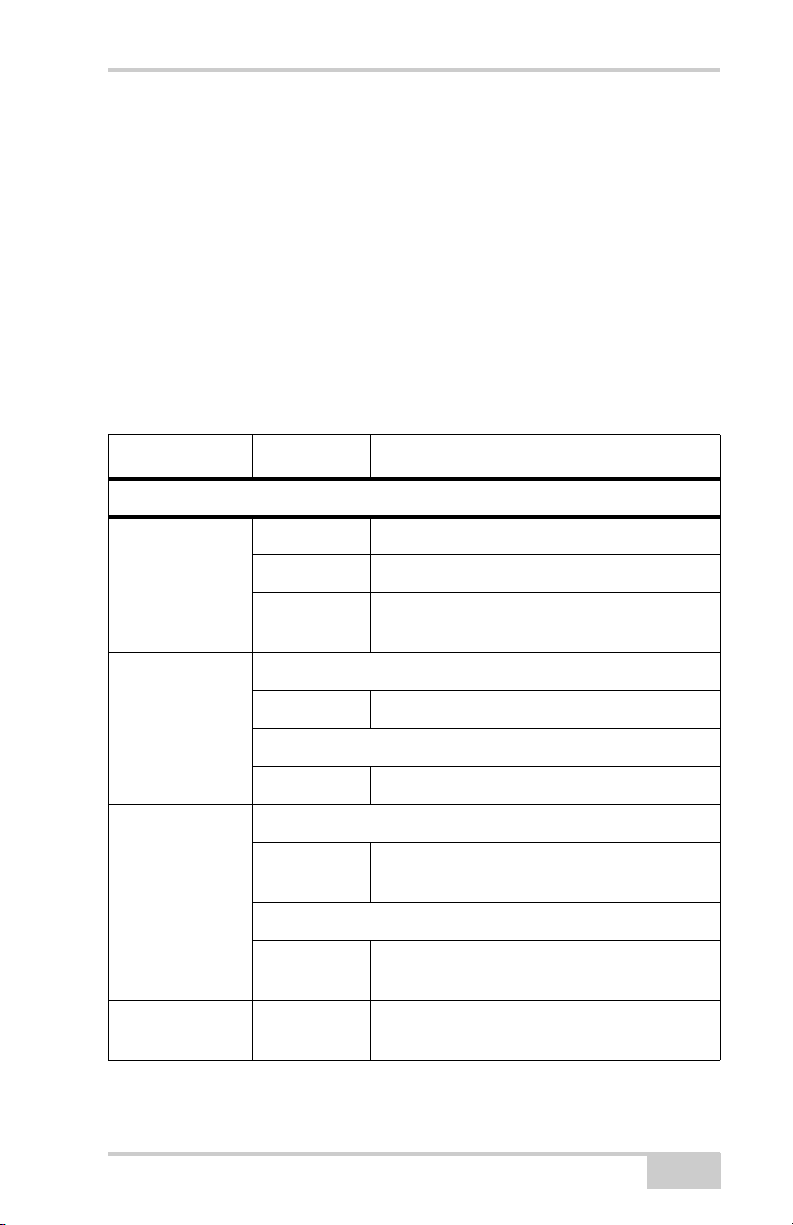
Table 1-2. FUNCTION Button Operations and REC LED Status
FUNCTION Key REC LED Status
When data recording is off, and the FUNCTION key is...
No light No data recording.
Not pressed
Pressed for < 1
second
Pressed for 1–5
seconds
Pressed for 5–8
seconds
Orange blink Internal file system test in progress.
Red No free memory; hardware problem with
data recording. No SDHC card.
If FUNCTION key mode is “LED blink mode switch”
Orange Release to change information mode.
If FUNCTION key mode is “Occupation mode switch”
Orange No function.
If FUNCTION key mode is “LED blink mode switch”
Green Release to start data recording (post-
processing occupation mode undefined).
If FUNCTION key mode is “Occupation mode switch”
Green Release to start recording (Kinematic or
Static post-processing occupation mode).
Red Release to turn serial port A baud rate to
9600 bps.
P/N 7010-1004
1-13

Introduction
Table 1-2. FUNCTION Button Operations and REC LED Status (Continued)
FUNCTION Key REC LED Status
Pressed for > 8
No light No function.
seconds
When data recording is on, and the FUNCTION key is...
Red No free memory; hardware problem with
data recording.
If FUNCTION key mode is “LED blink mode switch”
Green Data recording started (post-processing
occupation mode undefined).
Not pressed
If FUNCTION key mode is “Occupation mode switch”
Green Data recording started (Kinematic post-
processing occupation mode).
Orange Data recording started (Static post-
processing occupation mode).
If FUNCTION key mode is “LED blink mode switch”
Pressed for < 1
second
Orange Release to change information mode.
If FUNCTION key mode is “Occupation mode switch”
Orange Release to toggle between Static and
Kinematic post-processing modes.
Pressed for 1–5
seconds
Pressed for 5–8
seconds
Pressed for > 8
seconds
1-14
No light Release to stop data recording.
Red Release to turn serial port A baud rate to
9600 bps.
No light No function (data recording still on).
GR-5 Operator’s Manual
 Loading...