

Page 1
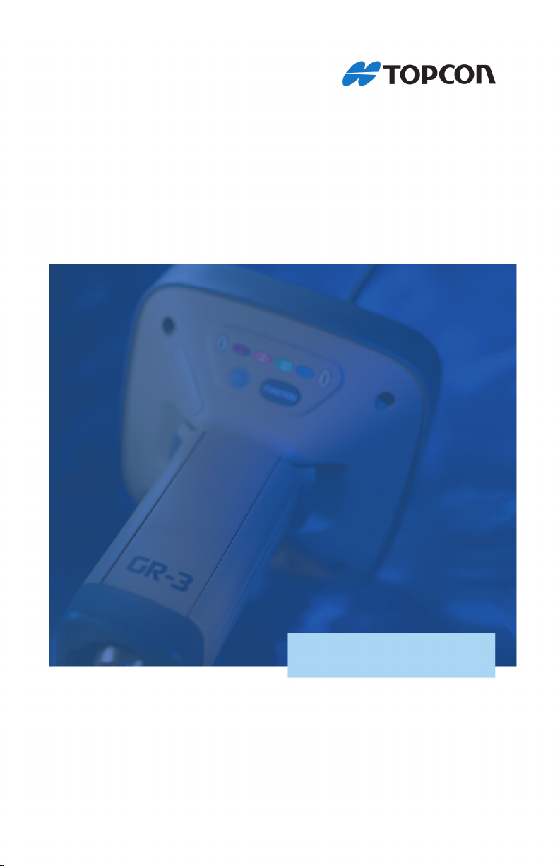
GR-3
Operator’s Manual
Page 2

Page 3

POSITIONING SYSTEMS
GR-3
Operator’s Manual
Part Number 7010-0736
Rev A
©Copyright Topcon Positioning Systems, Inc.
June, 2006
All contents in this manual are copyrighted by Topcon. All rights reserved.
The information contained herein may not be used, accessed, copied, stored,
displayed, sold, modified, published, or distributed, or otherwise reproduced
without express written consent from Topcon.
Topcon only sells GPS products into Precision Markets.
Please go to www.topcongps.com for detailed market information.
Page 4

ECO#2808
Page 5

TOC
Table of Contents
Preface .................................................................. v
Terms and Conditions ...................................................... v
Manual Conventions ........................................................ viii
Chapter 1
Introduction .......................................................... 1-1
Principles of Operation .................................................... 1-2
GNSS Overview ........................................................ 1-2
Calculating Absolute Positions ........................... 1-3
Calculating Differential Positions ...................... 1-4
Essential Components for Quality Surveying .... 1-5
Conclusion .......................................................... 1-6
Receiver Overview .................................................... 1-6
Getting Acquainted .......................................................... 1-8
Batteries ..................................................................... 1-8
GR-3 Receiver ........................................................... 1-10
MINTER ............................................................. 1-11
Data and Power Ports ......................................... 1-16
External Radio Antenna Connector .................... 1-17
Connector ............................................................ 1-17
SD/MMC and SIM Card Slots ............................ 1-18
Cables ........................................................................ 1-19
Other Accessories ...................................................... 1-20
Optional Accessories ................................................. 1-22
Option Authorization File (OAF) .................................... 1-23
Chapter 2
Pre-survey Preparation ........................................ 2-1
Installing Topcon Software .............................................. 2-2
Installing PC-CDU .................................................... 2-2
Installing Modem-TPS .............................................. 2-3
Installing BTCONF ................................................... 2-4
P/N 7010-0736
i
Page 6

Table of Contents
Installing FLoader ...................................................... 2-6
Installing the Optional SD and SIM Cards ....................... 2-7
Charging the Batteries ...................................................... 2-9
Power Management .......................................................... 2-10
Powering the Receiver ..................................................... 2-14
Using the Detachable Batteries .................................. 2-14
Using an Auxiliary Power Source ............................. 2-17
Turning On/Off the Receiver ..................................... 2-19
Connecting the Receiver and a Computer ........................ 2-19
Establishing a Wireless Connection .......................... 2-20
Establishing an RS232 Cable Connection ................. 2-21
Establishing a USB Connection ................................. 2-21
Bluetooth Module Configuration ..................................... 2-22
Collecting Almanacs and Ephemerides ............................ 2-26
Chapter 3
GR-3 Configuration .............................................. 3-1
Configuring the Radio Modem ........................................ 3-3
Configuring a Spread Spectrum Radio Modem ......... 3-3
Configuring a GSM Radio Modem ........................... 3-7
Configuring the Receiver ................................................. 3-10
MINTER Configuration ................................................... 3-20
Chapter 4
GR-3 Receiver Setup and Survey ....................... 4-1
Receiver Setup .................................................................. 4-1
Step 1: Set up the Receivers ...................................... 4-1
Step 2: Measure Antenna Height ............................... 4-4
Step 3: Collect Data ................................................... 4-6
MINTER Operation .......................................................... 4-7
Static Surveying for Base Stations ................................... 4-10
Kinematic (Stop & Go) Surveying for Rover Stations .... 4-11
Real Time Kinematic Surveying ...................................... 4-12
ii
GR-3 Operator’s Manual
Page 7

Table of Contents
Chapter 5
Receiver and File Maintenance ........................... 5-1
Downloading Files to a Computer ................................... 5-1
Downloading Files via Topcon Link ......................... 5-2
...Using Windows Explorer ................................ 5-2
...Using Topcon Link .......................................... 5-4
Downloading Files via PC-CDU ............................... 5-6
Deleting Files from the Receiver’s SD Card ................... 5-8
Managing Receiver Memory ........................................... 5-9
Managing Receiver Options ............................................ 5-10
Checking the Receiver’s OAF .................................. 5-10
Loading an OAF ........................................................ 5-12
Clearing the NVRAM ...................................................... 5-13
Using the MINTER to Clear the NVRAM ............... 5-13
Using PC-CDU to Clear the NVRAM ...................... 5-14
Changing Receiver Modes ............................................... 5-14
Entering Extended Information Mode ...................... 5-14
Sleep (Off) Mode ...................................................... 5-16
Loading New Firmware ................................................... 5-16
Loading Receiver and Power Board Firmware ......... 5-18
Chapter 6
Troubleshooting ................................................... 6-1
Check This First! ............................................................. 6-1
Troubleshooting Quick List ............................................. 6-2
Powering Problems .......................................................... 6-3
Receiver Problems ........................................................... 6-4
Bluetooth Problems ......................................................... 6-9
Modem-TPS Problems ..................................................... 6-12
TX RX LED Blink Pattern on Error Conditions ............. 6-13
Obtaining Technical Support ........................................... 6-14
Phone ......................................................................... 6-14
E-mail ........................................................................ 6-15
Website ...................................................................... 6-16
P/N 7010-0736
iii
Page 8

Table of Contents
Appendix A
Specifications ...................................................... A-1
Receiver Specifications .................................................... A-2
General Details .......................................................... A-2
GPS Board Details ..................................................... A-7
Bluetooth Module Details .......................................... A-8
Internal TPS Spread Spectrum Modem Details ......... A-9
Optional GSM/GPRS Module Details ....................... A-10
Connector Specifications .................................................. A-11
Radio (Modem) RF Connector .................................. A-11
Power Connector ....................................................... A-11
Serial C-RS232 Connector ........................................ A-12
USB Connector .......................................................... A-13
Appendix B
Safety Warnings ................................................... B-1
General Warnings ............................................................. B-1
Battery Pack Warnings ..................................................... B-2
Usage Warnings ............................................................... B-3
Appendix C
Regulatory Information ....................................... C-1
FCC Compliance .............................................................. C-1
Community of Europe Compliance .................................. C-2
WEEE Directive ............................................................... C-2
Appendix D
Warranty Terms ................................................... D-1
Index
iv
GR-3 Operator’s Manual
Page 9
Preface
Preface
Thank you for purchasing this Topcon product. The materials
available in this Manual (the “Manual”) have been prepared by
Topcon Positioning Systems, Inc. (“TPS”) for owners of Topcon
products, and are designed to assist owners with the use of the
receiver and its use is subject to these terms and conditions (the
“Terms and Conditions”).
NOTICE
Please read these Terms and Conditions carefully.
Terms and Conditions
USE This product is designed to be used by a professional. The user
should have a good knowledge of the safe use of the product and
implement the types of safety procedures recommended by the local
government protection agency for both private use and commercial
job sites.
COPYRIGHT All information contained in this Manual is the
intellectual property of, and copyrighted material of TPS. All rights
are reserved. You may not use, access, copy, store, display, create
derivative works of, sell, modify, publish, distribute, or allow any
third party access to, any graphics, content, information or data in this
Manual without TPS’ express written consent and may only use such
information for the care and operation of your receiver. The
information and data in this Manual are a valuable asset of TPS and
are developed by the expenditure of considerable work, time and
money, and are the result of original selection, coordination and
arrangement by TPS.
P/N 7010-0736
v
Page 10

Preface
TRADEMARKS GR-3™, Topcon Tools™, Topcon Link™,
TopSURV™, Modem-TPS™, Topcon® and Topcon Positioning
Systems™ are trademarks or registered trademarks of TPS.
Windows® is a registered trademark of Microsoft Corporation. The
Bluetooth® word mark and logos are owned by Bluetooth SIG, Inc.
and any use of such marks by Topcon Positioning Systems, Inc. is
used under license. Other product and company names mentioned
herein may be trademarks of their respective owners.
DISCLAIMER OF WARRANTY EXCEPT FOR ANY
WARRANTIES IN AN APPENDIX OR A WARRANTY CARD
ACCOMPANYING THE PRODUCT, THIS MANUAL AND THE
RECEIVER ARE PROVIDED “AS-IS.” THERE ARE NO OTHER
WARRANTIES. TPS DISCLAIMS ANY IMPLIED WARRANTY
OF MERCHANTABILITY OR FITNESS FOR ANY PARTICULAR
USE OR PURPOSE. TPS AND ITS DISTRIBUTORS SHALL NOT
BE LIABLE FOR TECHNICAL OR EDITORIAL ERRORS OR
OMISSIONS CONTAINED HEREIN; NOR FOR INCIDENTAL OR
CONSEQUENTIAL DAMAGES RESULTING FROM THE
FURNISHING, PERFORMANCE OR USE OF THIS MATERIAL
OR THE RECEIVER. SUCH DISCLAIMED DAMAGES
INCLUDE BUT ARE NOT LIMITED TO LOSS OF TIME, LOSS
OR DESTRUCTION OF DATA, LOSS OF PROFIT, SAVINGS OR
REVENUE, OR LOSS OF THE PRODUCT’S USE. IN ADDITION
TPS IS NOT RESPONSIBLE OR LIABLE FOR DAMAGES OR
COSTS INCURRED IN CONNECTION WITH OBTAINING
SUBSTITUTE PRODUCTS OR SOFTWARE, CLAIMS BY
OTHERS, INCONVENIENCE, OR ANY OTHER COSTS. IN ANY
EVENT, TPS SHALL HAVE NO LIABILITY FOR DAMAGES OR
OTHERWISE TO YOU OR ANY OTHER PERSON OR ENTITY
IN EXCESS OF THE PURCHASE PRICE FOR THE RECEIVER.
LICENSE AGREEMENT Use of any computer programs or software
supplied by TPS or downloaded from a TPS website (the “Software”)
in connection with the receiver constitutes acceptance of these Terms
and Conditions in this Manual and an agreement to abide by these
Terms and Conditions. The user is granted a personal, non-exclusive,
non-transferable license to use such Software under the terms stated
herein and in any case only with a single receiver or single computer.
vi
GR-3 Operator’s Manual
Page 11

Terms and Conditions
You may not assign or transfer the Software or this license without
the express written consent of TPS. This license is effective until
terminated. You may terminate the license at any time by destroying
the Software and Manual. TPS may terminate the license if you fail to
comply with any of the Terms or Conditions. You agree to destroy the
Software and manual upon termination of your use of the receiver. All
ownership, copyright and other intellectual property rights in and to
the Software belong to TPS. If these license terms are not acceptable,
return any unused software and manual.
CONFIDENTIALITY This Manual, its contents and the Software
(collectively, the “Confidential Information”) are the confidential and
proprietary information of TPS. You agree to treat TPS’ Confidential
Information with a degree of care no less stringent that the degree of
care you would use in safeguarding your own most valuable trade
secrets. Nothing in this paragraph shall restrict you from disclosing
Confidential Information to your employees as may be necessary or
appropriate to operate or care for the receiver. Such employees must
also keep the Confidentiality Information confidential. In the event you
become legally compelled to disclose any of the Confidential
Information, you shall give TPS immediate notice so that it may seek a
protective order or other appropriate remedy.
WEBSITE; OTHER STATEMENTS No statement contained at the
TPS website (or any other website) or in any other advertisements or
TPS literature or made by an employee or independent contractor of
TPS modifies these Terms and Conditions (including the Software
license, warranty and limitation of liability).
SAFETY Improper use of the receiver can lead to injury to persons or
property and/or malfunction of the product. The receiver should only
be repaired by authorized TPS warranty service centers. Users should
review and heed the safety warnings in an Appendix.
MISCELLANEOUS The above Terms and Conditions may be
amended, modified, superseded, or canceled, at any time by TPS. The
above Terms and Conditions will be governed by, and construed in
accordance with, the laws of the State of California, without reference
to conflict of laws.
P/N 7010-0736
vii
Page 12
Preface
Manual Conventions
This manual uses the following conventions:
Example Description
FileExit Click the File menu and click Exit.
Connection Indicates the name of a dialog box or screen.
Frequency Indicates a field on a dialog box or screen, or a tab
within a dialog box or screen.
Enter Press or click the button or key labeled Enter.
Further information to note about the configuration,
NOTE
TIP
maintenance, or setup of a system.
Supplementary information that can help you
configure, maintain, or set up a system.
NOTICE
CAUTION
WARNING
viii
Supplementary information that can have an affect
on system operation, system performance,
measurements, or personal safety.
Notification that an action has the potential to
adversely affect system operation, system
performance, data integrity, or personal health.
Notification that an action will result in system
damage, loss of data, loss of warranty, or personal
injury.
GR-3 Operator’s Manual
Page 13

Manual Conventions
DANGER
Under no circumstances should this action be
performed.
P/N 7010-0736
ix
Page 14

Preface
Notes:
x
GR-3 Operator’s Manual
Page 15
Chapter 1
Introduction
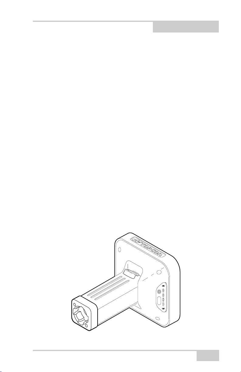
The GR-3 receiver is a multi-frequency, GPS+ receiver built to be the
most advanced and compact receiver for the surveying market. The
receiver is a multi-function, multi-purpose receiver intended for
precision markets. Precision markets means markets for equipment,
subsystems, components and software for surveying, construction,
commercial mapping, civil engineering, precision agriculture and
land-based construction and agriculture machine control,
photogrammetry mapping, hydrographic and any use reasonably
related to the foregoing.
The GR-3 can receive and processes multiple signal types (including
the latest GPS L2C, GPS L5, GLONASS C/A L2, and GALILEO
signals) improving the accuracy and reliability of your survey points
and positions, especially under difficult jobsite conditions. The multifrequency and GPS+ features of the receiver combine to provide a
positioning system accurate for any survey. Several other features,
including multipath mitigation, provide under-canopy and low signal
strength reception. The receiver provides the functionality, accuracy,
availability, and integrity needed for fast and easy data collection.
P/N 7010-0736
FUNCTION
Figure 1-1. GR-3 Receiver
1-1
Page 16

Introduction
Principles of Operation
Surveying with the right GPS receiver can provide users accurate and
precise positioning, a requirement for any surveying project.
This section gives an overview of existing and proposed Global
Navigation Satellite Systems (GNSS) and receiver functions to help
you understand and apply basic operating principles, allowing you to
get the most out of your receiver.
GNSS Overview
Currently, the following three global navigation satellite systems
(GNSS) offer line-of-site radio navigation and positioning, velocity,
and time services on a global, all-weather scale to any user equipped
with a GNSS tracking receiver on or near the Earth’s surface:
• GPS – the Global Positioning System maintained and operated by
the United States Department of Defense. For information on the
status of this system, visit the US Naval Observatory website
(http://tycho.usno.navy.mil/) or the US Coast Guard website
(http://www.navcen.uscg.gov/).
• GLONASS – the Global Navigation Satellite System maintained
and operated by the Russian Federation Ministry of Defense. For
information on the status of this system, visit the Coordinational
Scientific Information Center website (http://www.glonasscenter.ru/frame_e.html).
• GALILEO – an upcoming global positioning system maintained
and operated by Galileo Industries, a joint venture of several
European space agencies/companies working closely with the
European Space Agency. Unlike GPS and GLONASS, this is a
civil endeavor and is currently in the development and validation
stage. For information on the status of this system, visit the
Galileo Industries website (http://www.galileo-industries.net).
1-2
GR-3 Operator’s Manual
Page 17

Principles of Operation
Despite numerous technical differences in the implementation of
these systems, satellite positioning systems have three essential
components:
• Space – GPS, GLONASS, and GALILEO satellites orbit
approximately 12,000 nautical miles above Earth and are
equipped with a clock and radio. These satellites broadcast
ranging signals and various digital information (ephemerides,
almanacs, time&frequency corrections, etc.).
• Control – Ground stations located around the Earth that monitor
the satellites and upload data, including clock corrections and
new ephemerides (satellite positions as a function of time), to
ensure the satellites transmit data properly.
• User – The community and military that use GNSS receivers to
calculate positions.
Calculating Absolute Positions
When calculating an absolute position, a stationary or moving
receiver determines its three-dimensional position with respect to the
origin of an Earth-Center Earth-Fixed coordinate system. To calculate
this position, the receiver measures the distance (called pseudoranges) between it and at least four satellites. The measured pseudoranges are corrected for clock differences (receiver and satellites) and
signal propagation delays due to atmospheric effects. The positions of
the satellites are computed from the ephemeris data transmitted to the
receiver in navigation messages. When using a single satellite system,
the minimum number of satellites needed to compute a position is
four. In a mixed satellite scenario (GPS, GLONASS, GALILEO), the
receiver must lock onto five or more satellites to account for the
different time scales used in these systems and to obtain an absolute
position.
P/N 7010-0736
1-3
Page 18

Introduction
Calculating Differential Positions
DGPS, or Differential GPS, is a relative positioning technique where
the measurements from two or more remote receivers are combined
and processed using sophisticated algorithms to calculate the
receivers’ relative coordinates with high accuracy.
DGPS accommodates various implementation techniques that can be
classified according to the following criteria:
• The type of GNSS measurements used, either code-phase
differential measurements or carrier-phase differential
measurements
• If real-time or post-mission results required
Real-time applications can be further divided according to the
source of differential data and communication link used.
With DGPS in its most traditional approach, one receiver is placed at
a known, surveyed location and is referred to as the reference receiver
or base station. Another receiver is placed at an unknown location and
is referred to as the remote receiver or rover. The reference station
collects the code-phase and carrier-phase measurements from each
GNSS satellite in view.
• For real-time applications, these measurements and the reference
station coordinates are then built up to the industry standard
RTCM—or various proprietary standards established for
transmitting differential data—and broadcast to the remote
receiver(s) using a data communication link. The remote receiver
applies the transmitted measurement information to its observed
measurements of the same satellites.
• For post-mission applications, the simultaneous measurements
from reference and rover stations are normally recorded to the
receiver’s internal memory (not sent over communication link).
Later, the data are downloaded to computer, combined, and
processed.
Using this technique, the spatially correlated errors—such as
satellite orbital errors, ionospheric errors, and tropospheric
errors—can be significantly reduced, thus improving the position
solution accuracy.
1-4
GR-3 Operator’s Manual
Page 19

Principles of Operation
A number of differential positioning implementations exist, including
post-processing surveying, real-time kinematic surveying, maritime
radio beacons, geostationary satellites (as with the OmniSTAR
service), and satellite based augmentation systems (WAAS, EGNOS,
MSAS).
The real-time kinematic (RTK) method is the most precise method of
real-time surveying. RTK requires at least two receivers collecting
navigation data and communication data link between the receivers.
One of the receivers is usually at a known location (Base) and the
other is at an unknown location (Rover). The Base receiver collects
carrier phase measurements, generates RTK corrections, and sends
this data to the Rover receiver. The Rover processes this transmitted
data with its own carrier phase observations to compute its relative
position with high accuracy, achieving an RTK accuracy of up to 1 cm
horizontal and 1.5 cm vertical.
Essential Components for Quality Surveying
Achieving quality position results requires the following elements:
• Accuracy – The accuracy of a position primarily depends upon
the satellite geometry (Geometric Dilution of Precision, or
GDOP) and the measurement (ranging) errors.
– Differential positioning (DGPS and RTK) strongly mitigates
atmospheric and orbital errors, and counteracts Selective
Availability (SA) signals the US Department of Defense
transmits with GPS signals.
– The more satellites in view, the stronger the signal, the lower
the DOP number, the higher positioning accuracy.
• Availability – The availability of satellites affects the calculation
of valid positions. The more visible satellites available, the more
valid and accurate the position. Natural and man-made objects
can block, interrupt, and distort signals, lowering the number of
available satellites and adversely affecting signal reception.
P/N 7010-0736
1-5
Page 20

Introduction
• Integrity – Fault tolerance allows a position to have greater
integrity, increasing accuracy. Several factors combine to provide
fault tolerance, including:
– Receiver Autonomous Integrity Monitoring (RAIM) detects
faulty GNSS satellites and removes them from the position
calculation.
– Five or more visible satellites for only GPS or only
GLONASS; six or more satellites for mixed scenarios.
– Satellite Based Augmentation Systems (WAAS, EGNOS,
etc.) creates and transmit, along with DGPS corrections, data
integrity information (for example, satellite health warnings).
– Current ephemerides and almanacs.
Conclusion
This overview simply outlines the basics of satellite positioning. For
more detailed information, visit the TPS website.
Receiver Overview
When power is turned on and the receiver self-test completes, the
receiver’s 72 channels initialize and begin tracking visible satellites.
Each of the receiver’s channels can be used to track any one of the
GPS, GLONASS, or GALILEO signals. The number of channels
available allows the receiver to track all visible global positioning
satellites at any time and location.
An internal GPS+ antenna equipped with a low noise amplifier (LNA)
and the receiver’s radio frequency (RF) device are connected with a
coaxial cable. The wide-band signal received is down-converted,
filtered, digitized, and assigned to different channels. The receiver
processor controls the process of signal tracking.
Once the signal is locked in the channel, it is demodulated and
necessary signal parameters (carrier and code phases) are measured.
Also, broadcast navigation data are retrieved from the navigation
frame.
1-6
GR-3 Operator’s Manual
Page 21

Principles of Operation
After the receiver locks on to four or more satellites, its absolute
position in WGS-84 and the time offset between the receiver clock
and GPS time are computed. This information and the measurement
data can be stored in the optional MMC or SD card
1
and downloaded
later onto a computer, then processed using a post-processing
software package. When the receiver operates in RTK mode, raw data
measurements can also be recorded into the receiver’s internal
memory. This allows the operator to double check real-time results
obtained in the field.
Depending on your options, capabilities of the receiver include:
• Multipath reduction
• Satellite based augmentation systems (WAAS, EGNOS, etc.)
• Adjustable phase locked loop (PLL) and delay lock loop (DLL)
parameters
• Dual- or multi-frequency modes, including static, kinematic, realtime kinematic (RTK), and differential GPS (DGPS) survey
modes (DGPS modes include static, kinematic, and RTK)
• Auto data logging
• Setting different mask angles
• Setting different survey parameters
• Static or dynamic modes
1. MMC = multi-media card; SD = secure digital
P/N 7010-0736
1-7
Page 22
Introduction
Getting Acquainted
The GR-3 is a 72-channel GPS receiver with external, detachable
batteries, two data ports, an interface for controlling and viewing data
logging, external memory card slot, an internal radio modem, a
Bluetooth® wireless technology module, and an optional
GSM/GPRS module.
Batteries
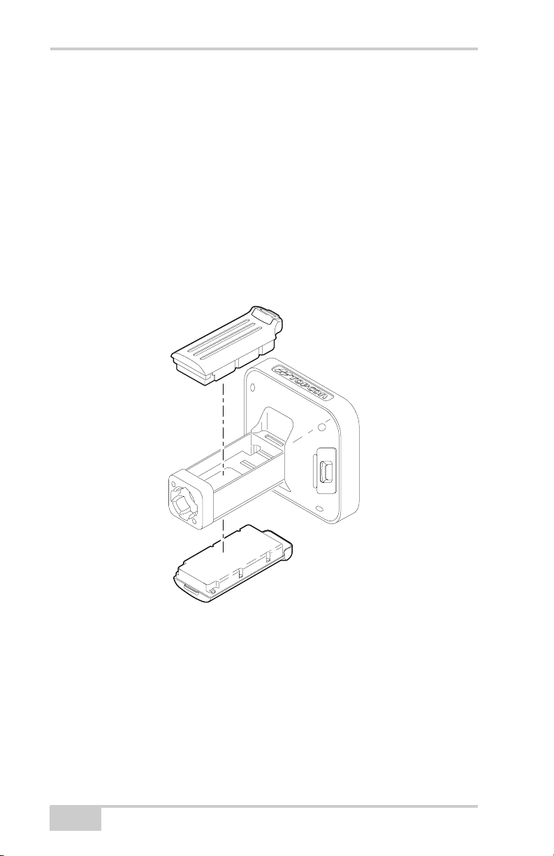
The GR-3 receiver comes equipped with two detachable,
rechargeable batteries (Figure 1-2) for powering the receiver.
Figure 1-2. GR-3 Batteries
The receiver draws power from one battery at a time before switching
to the second battery. Each detachable battery can provide up to
between 4h30m and 8h30m (approximate) of operation, depending on
the mode of the receiver.
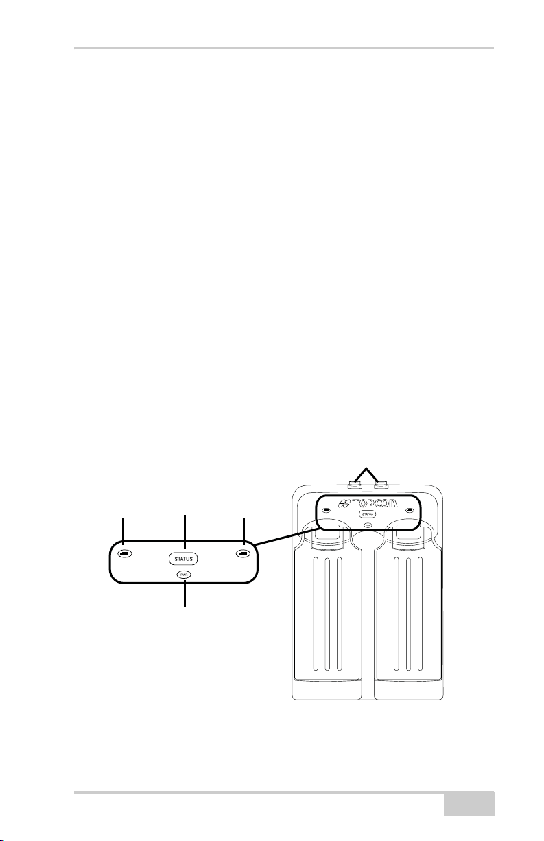
The battery charging cradle (Figure 1-3) connects to a standard
power outlet using the power adapter cable and power cable/power
supply unit. When connected to a power outlet, the batteries will be
1-8
GR-3 Operator’s Manual
Page 23
Getting Acquainted
fully charged in approximately six hours. The batteries should run at
no less than 80% capacity after 500 charging cycles. These batteries
do not need to be drained before recharging.
The charger has two ports, one button, and three LEDs.
• The two ports connect the charger to either a receiver or an
external power source. The ports charge or drain the batteries
simultaneously.
• The STATUS button activates the battery LEDs.
Press STATUS to display the amount of charge for the
corresponding battery.
• The two battery LEDs display the percentage of charge in the
attached battery.
– Green: indicates greater than 85% charge.
– Orange: indicates an intermediate charge.
– Red: indicates less than 15% charge.
• The power LED lights up when the charger is connected to an
external power source; such as an electrical outlet or another
power source (12 volt battery).
Two power in/out ports
STATUS
Battery
Button
Power
Figure 1-3. Battery Charger with Batteries
Battery
The battery charger can also be attached to a tripod, belt, or RTK pole
to provide external power to the base station or rover.
P/N 7010-0736
1-9
Page 24
Introduction
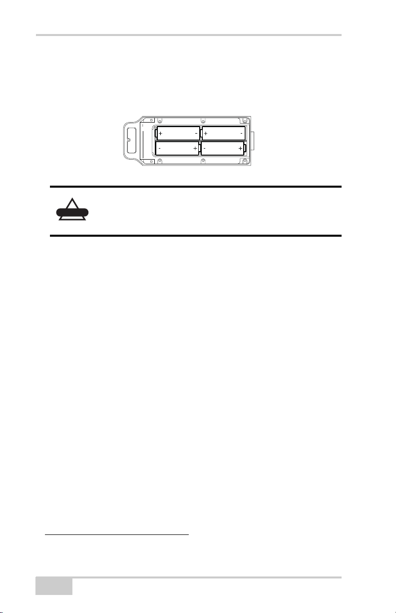
The AA battery shell (Figure 1-4) holds four AA batteries to provide
an easily portable backup power source for the receiver. Due to
variances in AA battery capacity, and the mode of the receiver and
type of modem, the amount of time the receiver is powered will vary.
Figure 1-4. AA Battery Shell (Open)
Do not use rechargeable AA batteries.
CAUTION
Do not use the AA battery shell when the radio
modem is in transmitter mode.
GR-3 Receiver
The GR-3 receiver’s advanced design reduces the number of cable
required for operation, allowing you to survey more reliably and
efficiently. The casing allocates space for two removable,
rechargeable batteries, SD/MMC and SIM card slots, a Bluetooth
wireless technology module, a multi-system receiver board, and a
radio modem communications board.
The GR-3 comes in one of the following configurations:
• with an FH915 Plus TX/RX/RP
1
radio modem
• with an FH915 Plus TX/RX/RP radio modem and a GSM/GPRS
module
• without a radio modem
Other features include two data ports, a power port, and a MINTER
for viewing status and controlling data input/output.
1. RP = repeater
1-10
GR-3 Operator’s Manual
Page 25
Getting Acquainted
MINTER
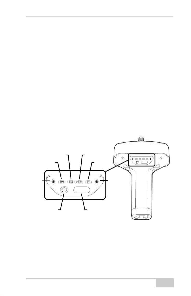
The MINTER is the receiver’s minimum interface used to display and
control data input and output (Figure 1-5).
The battery LEDs display the power status for each battery:
• Green – indicates greater than 85% charge.
• Orange – indicates an intermediate charge.
• Red – indicates less than 15% charge.
The STAT LED displays the status of tracked satellites.
• Red blink – receiver is on, but no satellites being tracked.
• Green blink – receiver is on and tracking satellites; one blink per
tracked GPS satellite.
• Orange blink – receiver is on and tracking satellites; one blink per
tracked GLONASS satellite.
STAT
Battery
Power
Button
P/N 7010-0736
REC RX TX
FUNCTION
FUNCTION
Button
Figure 1-5. GR-3 MINTER
BT
FUNCTION
Battery
1-11
Page 26

Introduction
The REC LED displays the data recording status. See “The
FUNCTION button” on page 1-13 for more information on REC
LED behavior when using the FUNCTION button.
• Green blinks – each blink indicates that data is being written to
the SD/MMC card.
• Solid Orange – indicates the receiver is changing modes.
• Orange blinks – indicates that the receiver is checking its internal
file system (after clearing the NVRAM or loading new firmware).
During this operation, the file system is not accessible for CDU
(control display unit) applications or for data recording. This
operation may require from fractions of a second to several
minutes, depending on the circumstances and the amount of
internal memory.
• Solid Red – indicates a fault condition with the receiver (no more
memory, no SD/MMC card inserted, a hardware problem, or an
improper OAF).
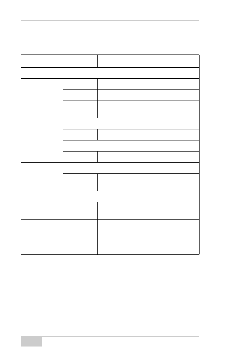
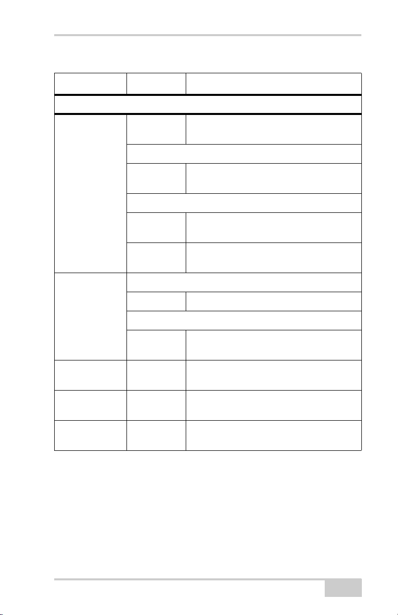
Table 1-2 on page 1-14 describes the REC LED status when using the
FUNCTION button.
The RX TX LED displays the status of the modem. Table 1-1
describes the LED colors and patterns for the different modems
available for the GR-3 receiver.
Table 1-1. RX TX LED Indications
• No light – modem is turned off.
• Green flashes – modem is in receiver mode.
• Solid Green – a radio link has been established; modem is
ready to receiver data.
FH915 Plus
Modem
1-12
• Solid Green plus Red flashes – modem is receiver data.
• Solid Red – modem is in transmitter mode.
• Red flashes – a fault condition has been detected. Check the
condition of the radio modem’s antenna to ensure it is
undamaged, and is connected properly and securely. Also make
sure nothing interrupts the signal.
• Red flashes plus Green flashes – modem is in command mode.
GR-3 Operator’s Manual
Page 27

Getting Acquainted
Table 1-1. RX TX LED Indications (Continued)
• Solid Orange (Red and Green) – the modem is initializing.
• Green flashes – the modem is on, registered on the network,
and is waiting for incoming calls (Slave mode).
GSM/GPRS
• Solid Red – a connection has been established.
• Green flashes – the modem is in direct control mode (Daisy
Chain).
• Orange flashes – an error has occurred (initialization error,
wrong PIN code, etc.).
The BT LED indicates the level of activity at the Bluetooth wireless
technology communication link:
• Blue flashes – the Bluetooth module is on but no connection is
established.
• Solid blue light – the Bluetooth module is on and a connection
has been established.
• No light – the Bluetooth module is off.
The power button turns the receiver on and off.
The FUNCTION button switches the receiver between information
modes and post-processing modes, starts/stops data recording, and
changes the baud rate of the serial port to 9600. See “MINTER
Operation” on page 4-7 for more information. Table 1-2 on page 1-14
describes the REC LED status when using the FUNCTION button.
P/N 7010-0736
1-13
Page 28
Introduction
Table 1-2. FUNCTION Button Operations and REC LED Status
FUNCTION Key REC LED Status
When data recording is off, and the FUNCTION key is...
No light No data recording.
Not pressed
Pressed for < 1
second
Pressed for 1–5
seconds
Pressed for 5–8
seconds
Pressed for > 8
seconds
Orange blink Internal file system test in progress.
Red No free memory; hardware problem with
data recording. No SD/MMC card.
If FUNCTION key mode is “LED blink mode switch”
Orange Release to change information mode.
If FUNCTION key mode is “Occupation mode switch”
Orange No function.
If FUNCTION key mode is “LED blink mode switch”
Green Release to start data recording (post-
processing occupation mode undefined).
If FUNCTION key mode is “Occupation mode switch”
Green Release to start recording (Kinematic or
Static post-processing occupation mode)
Red Release to turn serial port A baud rate to
9600 bps.
No light No function.
1-14
GR-3 Operator’s Manual
Page 29
Getting Acquainted
Table 1-2. FUNCTION Button Operations and REC LED Status (Continued)
FUNCTION Key REC LED Status
When data recording is on, and the FUNCTION key is...
Red No free memory; hardware problem with
data recording.
If FUNCTION key mode is “LED blink mode switch”
Green Data recording started (post-processing
occupation mode undefined).
Not pressed
Pressed for < 1
second
Pressed for 1–5
seconds
Pressed for 5–8
seconds
Pressed for > 8
seconds
If FUNCTION key mode is Occupation mode switch
Green Data recording started (Kinematic post-
processing occupation mode).
Orange Data recording started (Static post-
processing occupation mode).
If FUNCTION key mode is “LED blink mode switch”
Orange Release to change information mode.
If FUNCTION key mode is “Occupation mode switch”
Orange Release to toggle between Static and
Kinematic post-processing modes.
No light Release to stop data recording.
Red Release to turn serial port A baud rate to
9600 bps.
No light No function (data recording still on).
P/N 7010-0736
1-15
Page 30
Introduction
Data and Power Ports
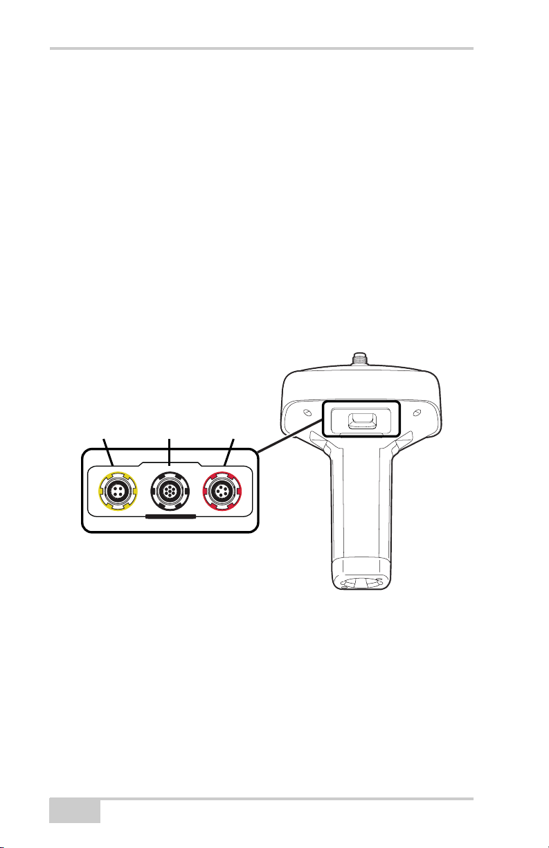
The GR-3 has the following three ports (Figure 1-6):
• USB – rimmed in yellow; used for high-speed data transfer and
communication between the receiver and an external device.
The body of the connector on the corresponding cable is yellow.
• Serial – rimmed in black; used for communication between the
receiver and an external device.
The body of the connector on the corresponding cable is black.
• Power – rimmed in red; used to connect the receiver to an
external power source. This port can also be used to charge the
batteries.
The body of the connector on the corresponding cable is red.
1-16
USB
(yellow)
U
S
B
(black)
S
E
R
I
A
L
Serial
Power
(red)
P
O
W
E
R
Figure 1-6. GR-3 Ports
GR-3 Operator’s Manual
Page 31
Getting Acquainted
External Radio Antenna Connector
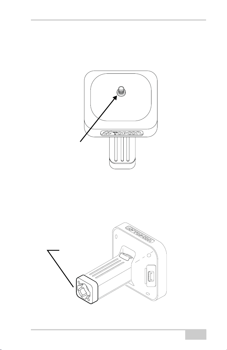
The SS antenna connects to the external antenna connector on the
GR-3 radome (Figure 1-7). The SS/GSM antenna uses a reverse
polarity TNC connection.
External
Antenna
Connector
Figure 1-7. GR-3 Radome and External Antenna Connector
Connector
The bottom connector (Figure 1-8) connects the receiver to either a
standard 5/8'' thread pole/adapter or the quick disconnect (see “The
quick disconnect adapter” on page 1-21 for details).
Bottom Connector
for Standard Setups
Figure 1-8. GR-3 Quick Connector
P/N 7010-0736
1-17
Page 32
Introduction
SD/MMC and SIM Card Slots
The SD/MMC1 and SIM card slots reside under the batteries near the
base of the dome.
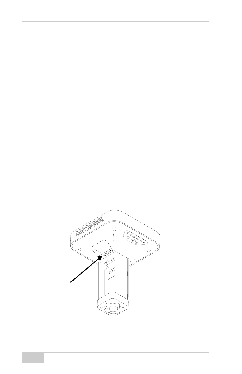
The SD/MMC card slot is located to the left of the MINTER inside
the battery pocket (Figure 1-9) and connects an optional SD/MMC
card to the receiver board to provide memory. Once installed, the SD/
MMC card usually remains inside the receiver. The data that resides
on the SD/MMC card can be accessed via the USB or serial port, or
Bluetooth wireless technology. A secure digital card can be purchased
at your local computer supply store.
The SIM card slot is located to the right of the MINTER inside the
battery pocket and allows a standard SIM card to be installed in the
receiver. Once installed, the SIM card provides a unique identification
for the receiver’s GSM module and enables the receiver’s GSM
functionality based on the subscribed services (the receiver board
accesses the GSM module which accesses the SIM card). The SIM
card usually remains inside the receiver. The GSM module with the
SIM card installed can be accessed via Modem-TPS for configuration
purposes. A SIM card can be purchased from your local cellular
provider.
Card Slot
(for SD/MMC card)
Figure 1-9. GR-3 Card Slot Example
1. MMC = multi-media card; SD = secure digital
1-18
GR-3 Operator’s Manual
Page 33
Getting Acquainted
Cables
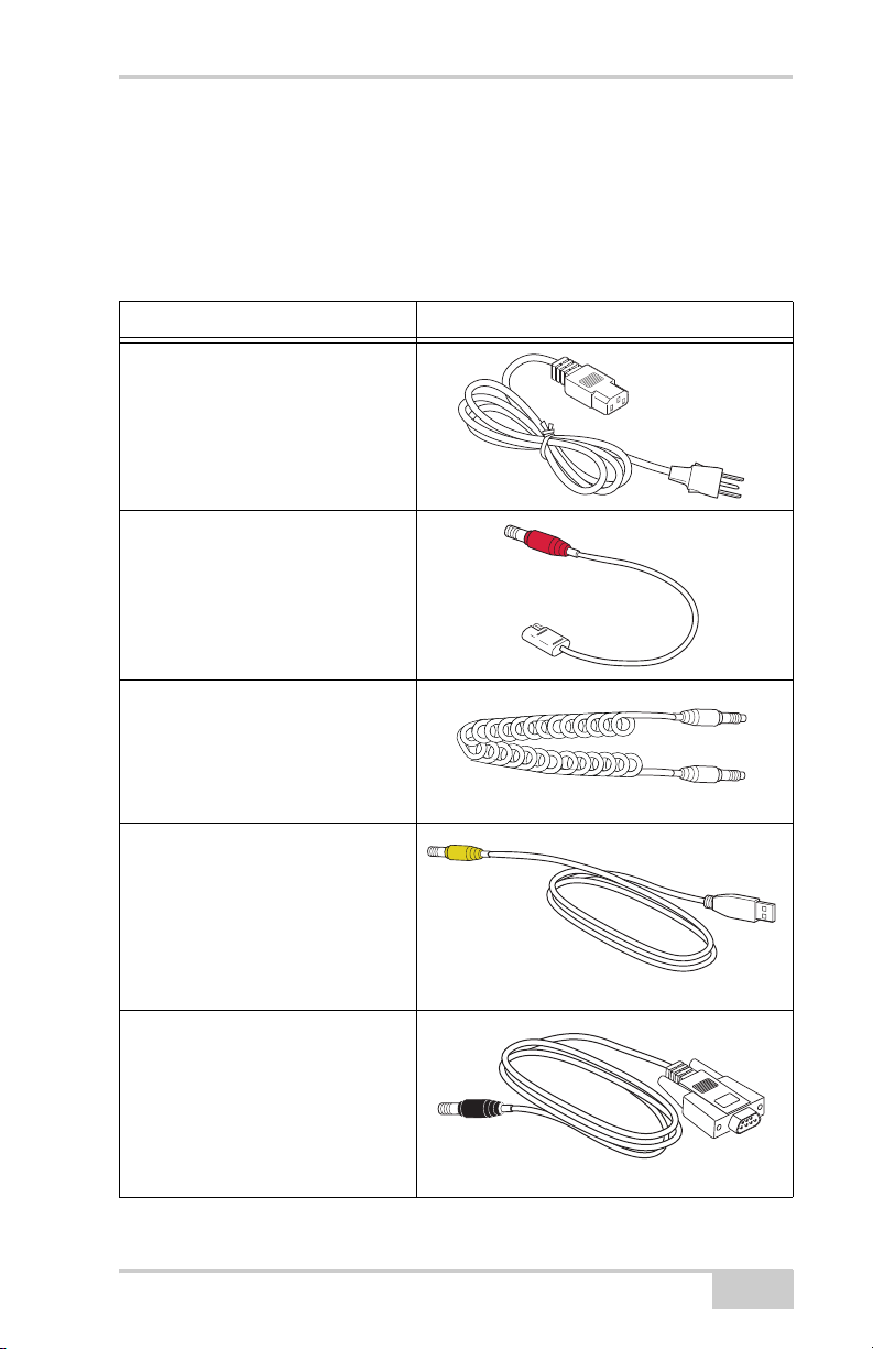
The GR-3 package includes standard communication and power
cables for configuring the receiver and providing a power source to
the receiver. Table 1-3 lists the cables included in the GR-3 package.
Table 1-3. GR-3 Package Cables
Cable Description Cable Illustration
Power cable
Connects the power supply unit to a
grounded outlet.
U.S. p/n 14-008052-01
Europe p/n 14-008054-01
Australia p/n 14-008053-01
Receiver power/charging cable
Connects the receiver and the
power supply unit via SAE
connectors for battery charging.
Body of connector is red.
p/n 14-008016-03
Cradle-to-receiver charging cable
Connects the receiver to the
charging cradle for external power.
p/n 14-008072-01 (1.5m long)
p/n 14-008072-02 (0.5 m long)
USB cable
Connects the receiver to an external
device (controller or computer) for
high-speed data transfer and
receiver configuration. Body of
connector is yellow.
p/n 14-008070-01
Serial cable
Connects the receiver to an external
device (controller or computer) for
data transfer and receiver
configuration. Body of connector is
black.
p/n 14-008005-02
P/N 7010-0736
1-19
Page 34
Introduction
Other Accessories
Along with the following accessories, the GR-3 package includes a
128 MB SD memory card, 3-meter measuring tape, an adjustable
range pole, and a cable bag.
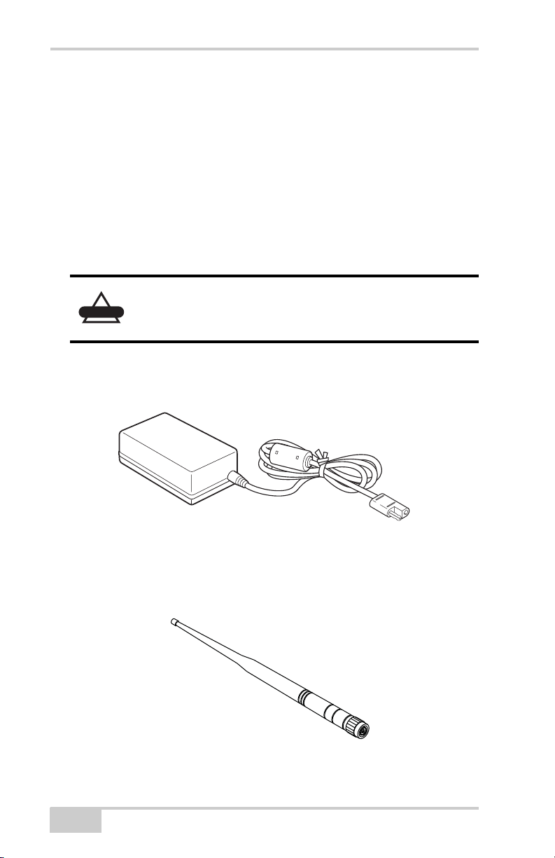
The Power Supply unit (p/n 22-034101-01) charges the internal
batteries when connected to a grounded outlet (Figure 1-10). This
unit converts the alternating current (AC) normally supplied from an
electrical outlet to a direct current (DC) used to charge the batteries
and/or power the receiver.
The power supply unit should only be used for
CAUTION
The power supply unit can be connected to the charging cradle or
directly to the receiver. For details, see the power related sections in
Chapter 2.
charging the batteries. Do not use as a power source
during surveying.
Figure 1-10. Power Supply Unit
The modem antenna Spread Spectrum includes support for a GSM
modem (Figure 1-11 on page 1-20). The Spread Spectrum antenna is
a reverse polarity TNC RF connection (p/n 30-030012-01).
SS/GSM Antenna
Figure 1-11. Modem Antenna
1-20
GR-3 Operator’s Manual
Page 35
Getting Acquainted
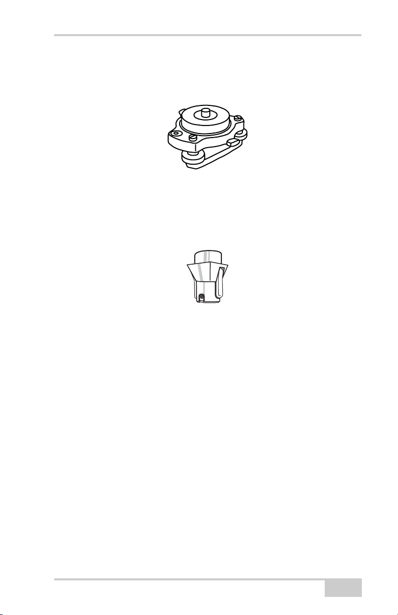
The universal tribrach and tribrach adapter (p/n 22-006008-01
and p/n 22-006009-011) are used to level the tripod and secure the
receiver or antenna to the tripod (Figure 1-12).
Figure 1-12. Universal Tribrach and Tribrach Adapter
The quick disconnect adapter (p/n 02-850905-01) connects to the
range pole for the receiver to slip into the top. Using the side clips, the
receiver can be quickly connected to/disconnected from the range
pole (Figure 1-13).
Figure 1-13. Quick Disconnect
For more details on the accessories and package options available for
the GR-3, contact your local Topcon dealer.
P/N 7010-0736
1-21
Page 36
Introduction
Optional Accessories
Topcon offers a wide variety of accessories especially designed to
extend your job reliability and efficiency. For more details on the
optional accessories available for the GR-3, contact your local
Topcon dealer.
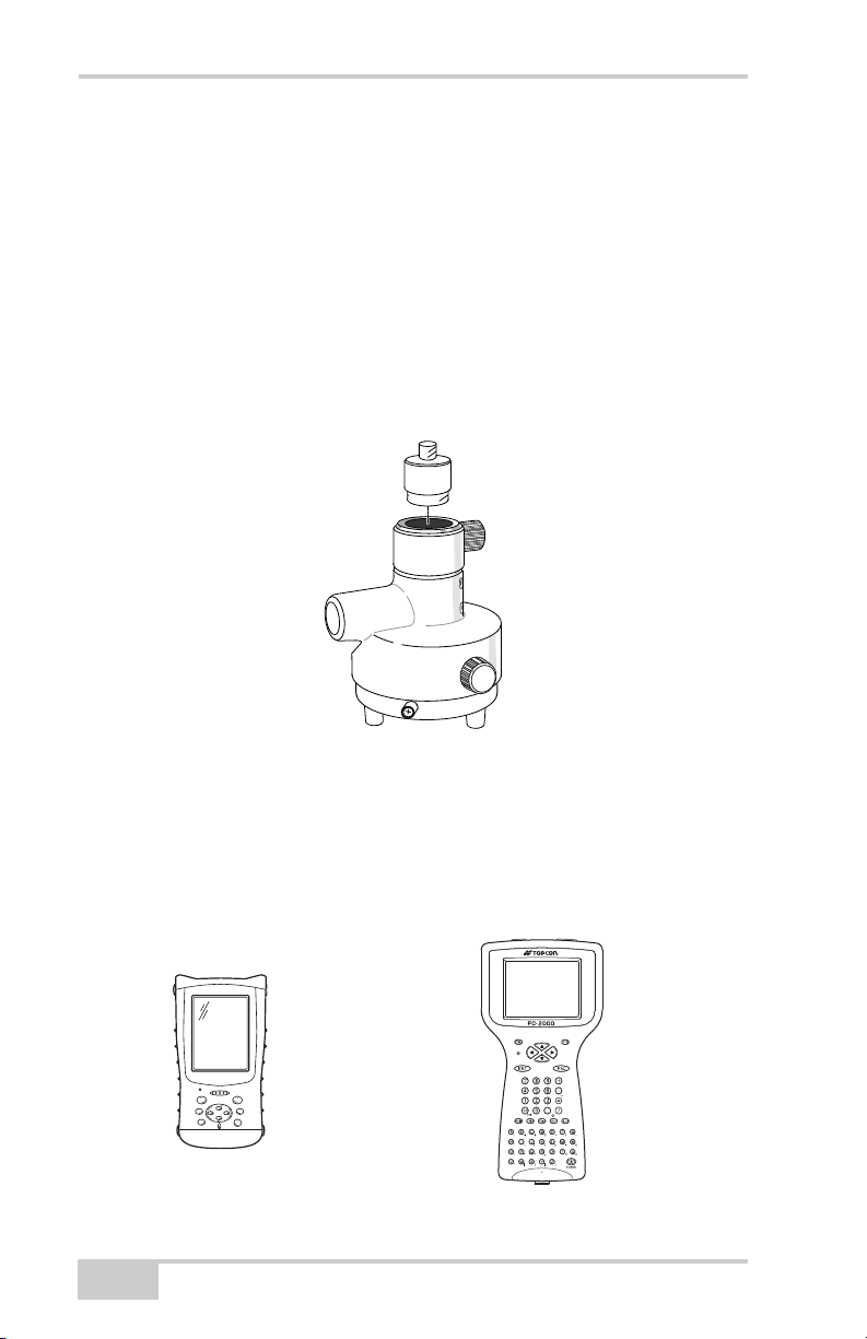
The precision tribrach adapter (Figure 1-14) is used to precisely
center, align, and level the tripod over a point. The horizontal spacer
(p/n 60419) inserts into the precision tribrach and allows the receiver
to sit securely on the precision tribrach.
Figure 1-14. Precision Tribrach Adapter and Horizontal Spacer
A hand-held controller (Figure 1-15) allows the GR-3 Base and
Rover systems to be configured and monitored directly in the field.
TopSURV (field data collection software) and CE-CDU (receiver
configuration and monitoring software) can be used on Topcon
controllers to configure and manage the receiver.
FC-100 FC-2000
Figure 1-15. Hand-held Controller Examples
1-22
GR-3 Operator’s Manual
Page 37
Option Authorization File (OAF)
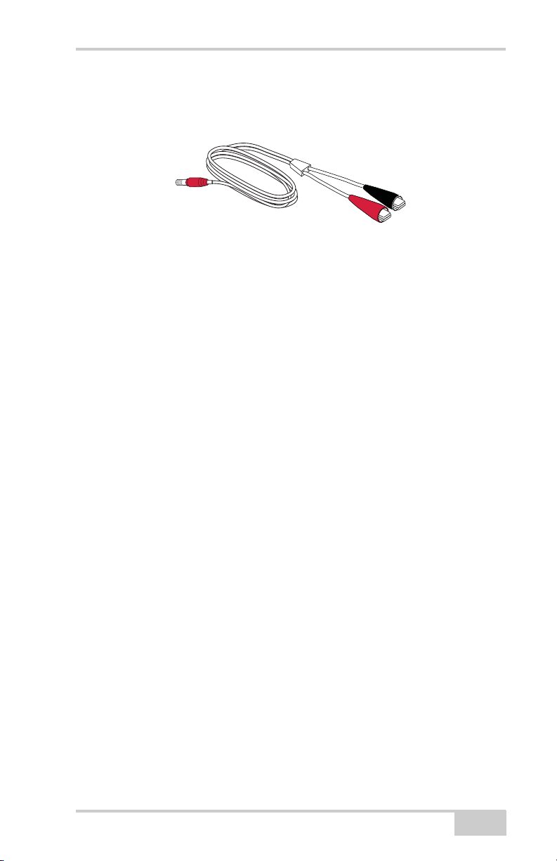
The ODU-to-alligator clips cable (p/n 14-008097-01LF) connects
the charging cradle or receiver to an auxiliary battery for powering the
receiver during survey operations (Figure 1-13).
Figure 1-16. Auxiliary Power Cable – ODU-to-Alligator Clips
Option Authorization File (OAF)
Topcon Positioning Systems issues an Option Authorization File
(OAF) to enable the specific options that customers purchase. An
Option Authorization File allows customers to customize and
configure the receiver according to particular needs, thus only
purchasing those options needed.
Typically, all receivers ship with a temporary OAF that allows it to be
used for a predetermined period of time. When the receiver is
purchased, a new OAF permanently activates desired, purchased
options. Receiver options remain intact when clearing the NVRAM or
resetting the receiver.
The OAF enables the following kinds of functions. For a complete list
of available options and details, visit the TPS website or consult your
TPS dealer.
• Type of signal (standard L1; optional L2, L5 GPS, GLONASS,
GALILEO)
• External SD memory card
• Update rate standard 1Hz (optional 5, 10, or 20Hz)
• RTK at 1Hz, 5Hz, 10Hz, and 20Hz
• RTCM/CMR Input/Output
• Advanced multipath reduction
• Wide Area Augmentation System (WAAS)
• Receiver Autonomous Integrity Monitoring (RAIM)
P/N 7010-0736
1-23
Page 38

Introduction
Notes:
1-24
GR-3 Operator’s Manual
Page 39

Chapter 2
Pre-survey
Preparation
Before beginning to survey with the GR-3 receiver, the following
software needs to be installed and configurations need to be applied:
Install receiver configuration software
See “Installing Topcon Software” on page 2-2.
Optional: install SD card and/or SIM card
See “Installing the Optional SD and SIM Cards” on page 2-7.
Charge the batteries
See “Charging the Batteries” on page 2-9.
Enable power source settings (either attached or external)
See “Power Management” on page 2-10 and “Powering the
Receiver” on page 2-14.
Configure the Bluetooth wireless technology module
See “Bluetooth Module Configuration” on page 2-22.
Collect almanacs and ephemerides (after first-time configuration
activities as described in Chapter 3)
See “Collecting Almanacs and Ephemerides” on page 2-26.
This chapter also discusses connecting batteries to the receiver,
connecting the receiver and a computer, and powering the receiver
using different sources.
P/N 7010-0736
2-1
Page 40

Pre-survey Preparation
Installing Topcon Software
The Topcon GPS+ CD includes the following software programs used
for configuring and maintaining the receiver. This software is also
available on the TPS website to registered users.
• PC-CDU Lite
ver. 2.1.15 or newer
•Modem-TPS
ver. 2.0 or newer
• BTCONF
ver. 1.2 or newer
• FLoader
ver 1.0.07 or newer
If installing the program(s) from the GPS+ CD, insert the CD into the
computer’s CD-ROM drive. If downloading the program(s) from the
website, extract the program’s files into a folder on your hard drive.
The following sections describe installing this software, and other
sections throughout the manual describe using this software with the
receiver.
Installing PC-CDU
PC-CDU™ is a comprehensive Windows® software product
designed for controlling GPS+ receivers developed by Topcon
Positioning Systems. PC-CDU uses the GPS Receiver Interface
Language (GRIL) to configure various receiver settings and diagnose
receiver performance.
The PC-CDU software exists in two versions: a full-functionality
version called PC-CDU MS and a reduced-functionality version
called PC-CDU Lite. PC-CDU Lite is available for free on the Topcon
website or the GPS+ CD.
Computer requirements for PC-CDU are: Windows® 98 or newer and
an RS-232C or USB port, or Bluetooth capable. Use PC-CDU version
2.1.15 or newer to correctly configure the receiver.
NOTICE
2-2
Refer to the PC-CDU Reference Manual for full
details on installing and using PC-CDU.
GR-3 Operator’s Manual
Page 41
Installing Topcon Software
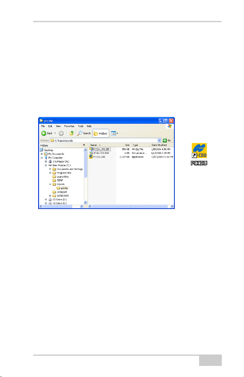
1. Create a PC-CDU folder on your hard drive and place the
compressed PC-CDU zip file (retrieved from either the website or
the GPS+ CD) in this folder.
2. Navigate to the PC-CDU folder and double-click the PC-CDU
zip file.
3. Extract the PCCDU.EXE and associated *.dll file to the PC-CDU
folder (Figure 2-1).
4. Create a shortcut on the computer’s desktop for quick access to
PC-CDU (Figure 2-1).
Figure 2-1. Extract Program and Create Shortcut
To uninstall PC-CDU, navigate to the location of the *.exe file. Select
the file and press Delete.
Installing Modem-TPS
Modem-TPS is a configuration program for the radio modem board
inside the receiver. Modem-TPS is available from the TPS website or
on the GPS+ CD.
Computer requirements for Modem-TPS are: Windows® 98 or newer
and an RS-232C port or Bluetooth wireless technology. Use ModemTPS version 2.0 or newer to correctly configure the receiver.
1. Navigate to the location of the Modem-TPS program and doubleclick the Setup.exe icon.
P/N 7010-0736
2-3
Page 42
Pre-survey Preparation
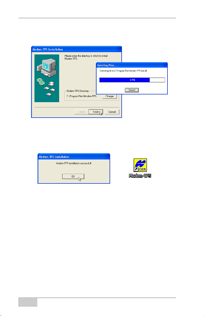
2. Keep the default installation location or select a new location.
Click Finish (Figure 2-2).
Figure 2-2. Select Modem-TPS Installation Location and Install
3. Click OK to complete the installation (Figure 2-3).
4. If desired, create a shortcut on the computer’s desktop for quick
access to Modem-TPS (Figure 2-3).
Figure 2-3. Installation Complete and Shortcut
To uninstall Modem-TPS, use the Start menu on your computer:
Click StartProgramsModem-TPSUninstall Modem-
TPS, and click Ye s at the prompt. Then click OK when the
uninstall completes.
Installing BTCONF
BTCONF is configuration program for the Bluetooth wireless
technology module inside the receiver. BTCONF is available from the
TPS website or on the GPS+ CD.
Computer requirements for BTCONF are: Windows® 98 or newer
and an RS-232C port or Bluetooth wireless technology. Use
BTCONF version 1.2 or newer to correctly configure the receiver.
2-4
GR-3 Operator’s Manual
Page 43
Installing Topcon Software
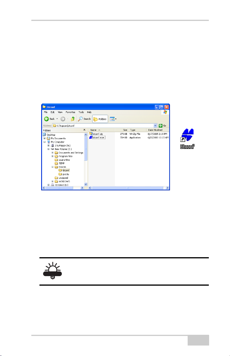
1. Create a BTCONF folder on your hard drive and place the
compressed BTCONF zip file (retrieved from either the website
or the GPS+ CD) in this folder.
2. Navigate to the BTCONF folder and double-click the BTCONF
zip file.
3. Extract the btconf.exe to the BTCONF folder.
4. Create a shortcut on the computer’s desktop for quick access to
BTCONF (Figure 2-4).
Figure 2-4. Extract Program and Create Shortcut
To uninstall BTCONF, navigate to the location of the *.exe file. Select
the file and press Delete.
Each time you run BTCONF and configure the Bluetooth module,
BTCONF saves the settings in a file (btconf.ini). BTCONF
automatically updates the file each time you make changes to the
Bluetooth module’s settings.
To maintain unique Bluetooth module settings for
TIP
different purposes, keep copies of BTCONF in
separate folders.
P/N 7010-0736
2-5
Page 44
Pre-survey Preparation
Installing FLoader
FLoader is a firmware loading program for the power board, GPS
module, and modem board inside the receiver. FLoader is available
from the TPS website or on the GPS+ CD.
Computer requirements for FLoader are: Windows® 98 or newer and
an RS-232C port or Bluetooth wireless technology. Use FLoader
version 1.0.07 or newer to correctly configure the receiver.
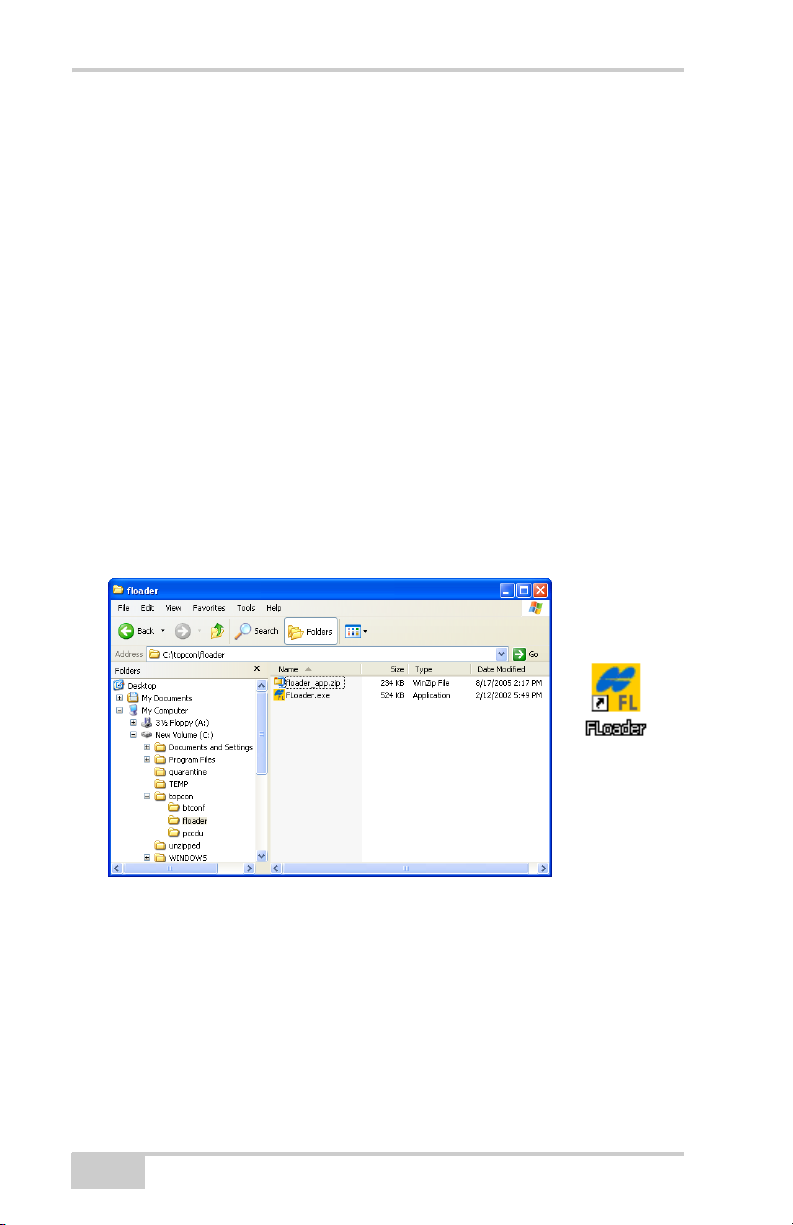
1. Create an FLoader folder on your hard drive and place the
compressed FLoader zip file (retrieved from either the website or
the GPS+ CD) in this folder.
2. Navigate to the FLoader folder and double-click the FLoader zip
file.
3. Extract the FLoader.exe to the FLoader folder (Figure 2-5).
4. Create a shortcut on the computer’s desktop for quick access to
FLoader (Figure 2-5).
Figure 2-5. Extract Program and Create Shortcut
To uninstall FLoader, navigate to the location of the *.exe file. Select
the file and press Delete.
2-6
GR-3 Operator’s Manual
Page 45
Installing the Optional SD and SIM Cards
Installing the Optional SD and
SIM Cards
Behind each detachable battery is a slot for the optional SD card or
the optional SIM card. The SD card provides memory space in which
to save logged data; the SIM card provides telephony communication
for data transfer between two GSM-capable receivers. The SD card
can be purchased at your local computer store; the SIM card can be
purchased at your local cellular phone supply store. The receiver
currently supports an SD card with up to 1GB capacity.
Once installed, the card(s) generally remains installed. The card can
then be accessed via the receiver board using a data port or Bluetooth
wireless technology.
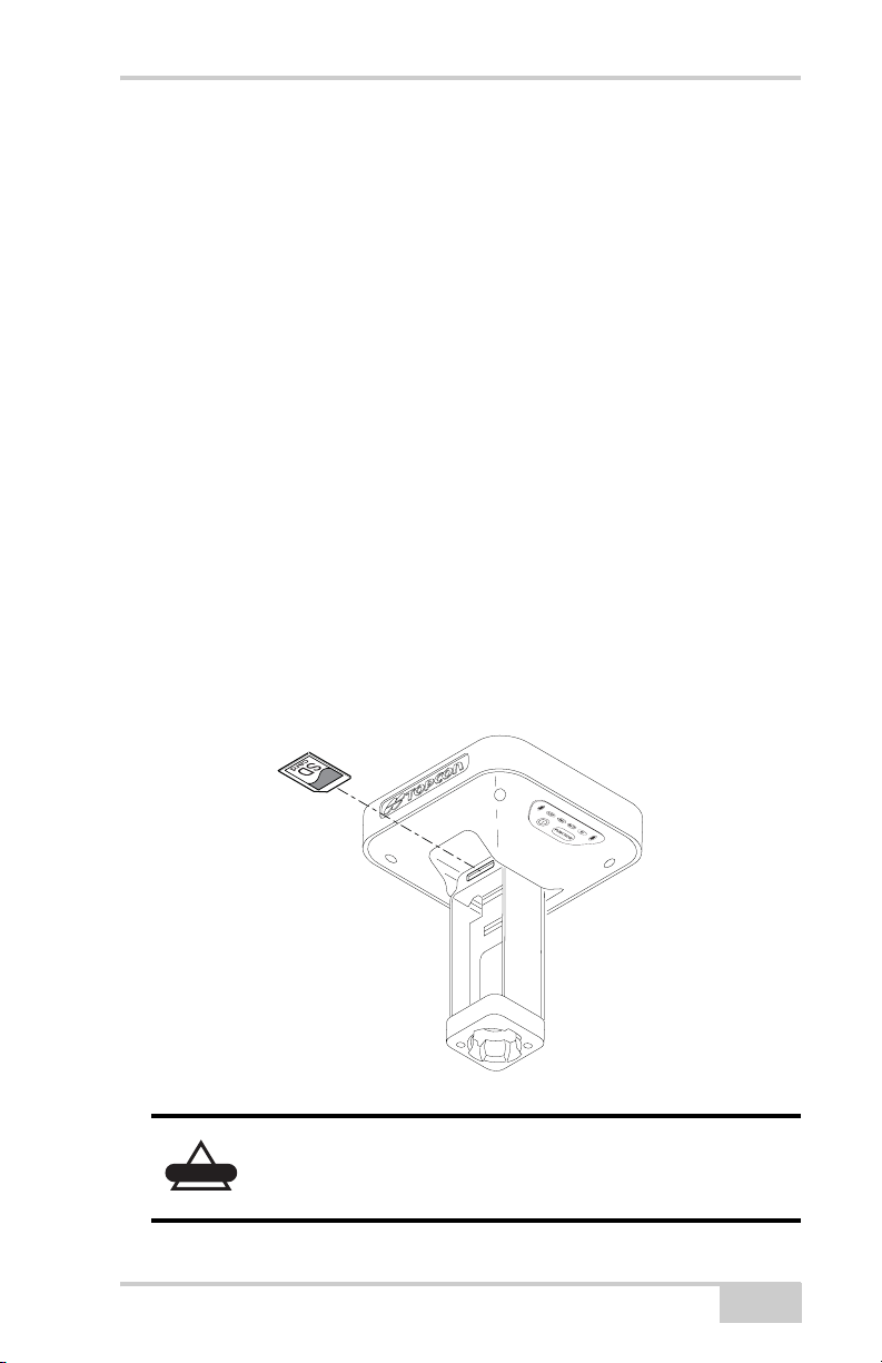
To install the SD card (Figure 2-6):
1. Ensure the receiver is turned off.
2. Remove the battery to the left of the MINTER.
3. Carefully insert the SD card, label side down, into the SD card
slot located at the top of the battery pocket.
CAUTION
P/N 7010-0736
Figure 2-6. Install SD Card
Do not remove the card if the receiver is powered
on. Damage to data may result from improper
removal of the card.
2-7
Page 46
Pre-survey Preparation
Once the receiver is turned on, the receiver board will detect the SD
card and it will be ready to use as needed.
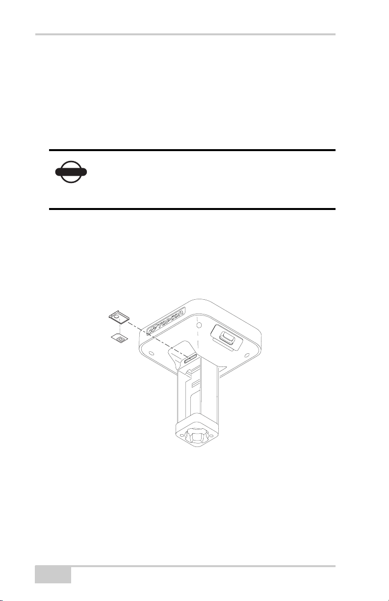
To install the SIM card (Figure 2-7):
The SIM card must support Circuit Switched Data to communicate
directly between receivers. The SIM card must have GPRS support to
communicate with a GPS Network IP address.
Both the Base and Rover receivers must have a SIM
NOTICE
card installed (supporting Circuit Switched Data)
and have subscriptions to the same service provider
for proper communication.
1. Ensure the receiver is turned off.
2. Remove the battery to the right of the MINTER.
3. If needed, snap the SIM card into its holder.
4. Carefully insert the holder, label side down, into the SIM card slot
located at the top of the battery pocket.
Figure 2-7. Install SIM Card
Once the receiver is turned on, the receiver board will detect the SIM
card and it will be ready to use as needed.
2-8
GR-3 Operator’s Manual
Page 47
Charging the Batteries
Charging the Batteries
Before beginning to work, fully charge the batteries for maximum
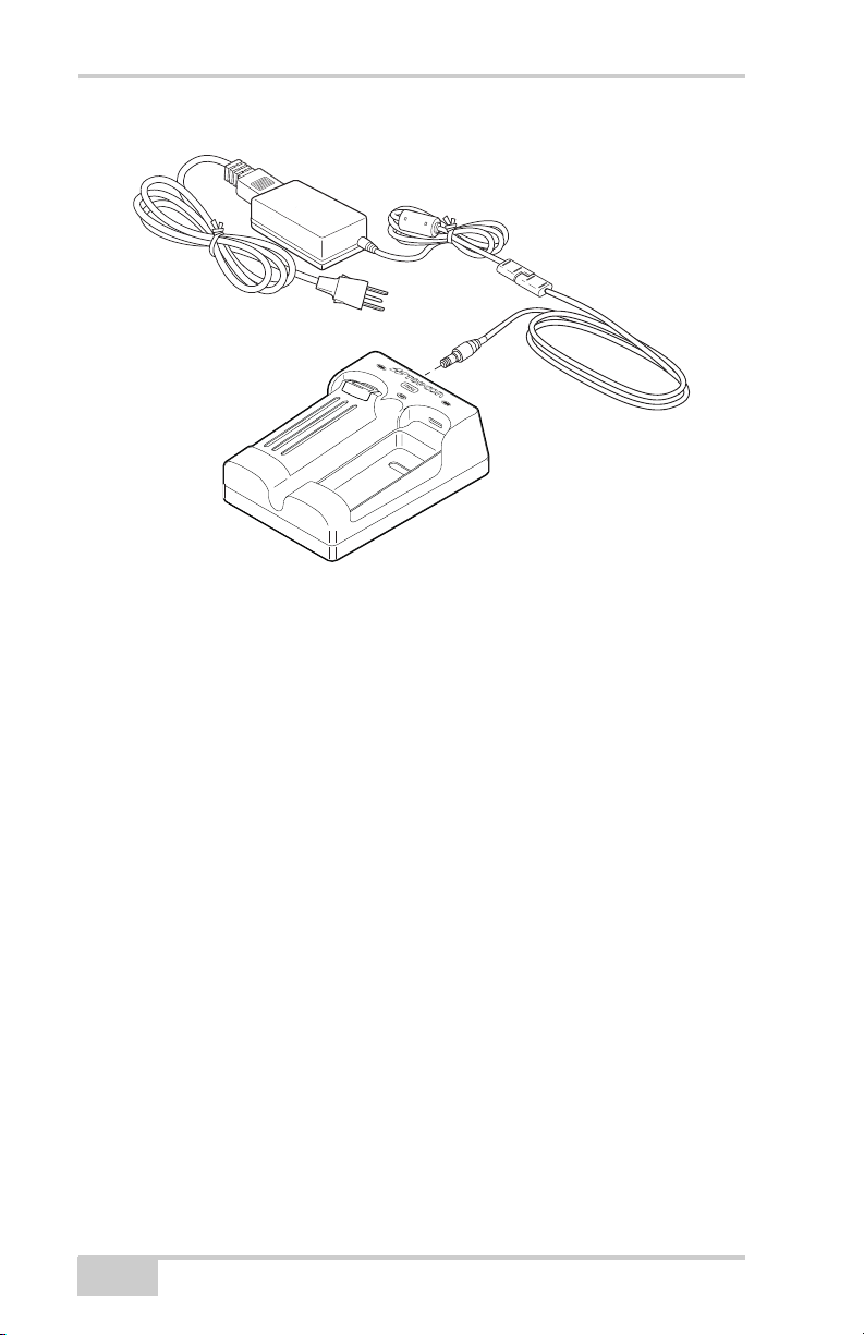
operating time (Figure 2-8 on page 2-10).
• If the batteries are attached to the charging cradle, an
approximately 6-hour charge cycle will fully charge the batteries;
the batteries will charge simultaneously.
• If the batteries are attached to the GR-3, an approximately 6-hour
charge cycle will fully charge the batteries; the batteries will
charge simultaneously.
The batteries can not be overcharged.
NOTE
power. Fully charge the batteries before surveying.
Each detachable battery can provide up to between 4.5 and 8.5 hours
(approximate, at room temperature) of operation, depending on the
mode of the receiver.
If the batteries are attached to the receiver, connect
The batteries are shipped from the factory without
TIP
the power adapter cable to the receiver’s power port
to charge the batteries. The batteries will charge
simultaneously.
1. Remove the batteries from the receiver and insert them into the
charging cradle.
2. Connect the power cable to the power supply unit.
3. Connect the SAE connectors on the power adapter cable and
power supply unit.
4. Connect the power adapter cable to one of the ports on the
charging cradle (either port will charge both/either battery).
5. Plug the power supply to an available outlet. Leave for
approximately 6 hours to fully charge the batteries.
P/N 7010-0736
2-9
Page 48
Pre-survey Preparation
To grounded outlet
Figure 2-8. Insert Batteries in Charger and Connect to Outlet
The Li-Ion batteries used in the battery packs should run at no less
than 80% capacity after 500 charging cycles. These batteries do not
need to be drained before recharging.
Power Management
Topcon’s PC-CDU software provides an interface for various
configuration, monitoring, and management functions for the
receiver.
For power management of the receiver, PC-CDU enables the power
source, enables the charging mode, and displays the current voltage
for the batteries.
1. Connect your receiver and computer. See “Connecting the
Receiver and a Computer” on page 2-19 for this procedure.
2. Once connected, click ConfigurationReceiver.
2-10
GR-3 Operator’s Manual
Page 49
Power Management
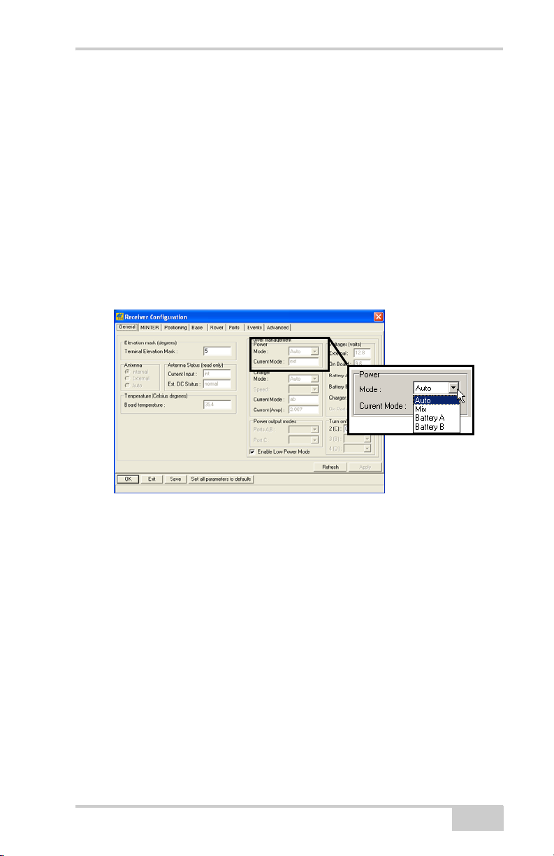
3. Select the Power Mode drop-down list to set the desired power
source (Figure 2-9). Current Mode displays the current power
source; if using the cradle, it will show “extbat.”
• Auto – receiver automatically selects the power source
• Mix – the batteries will discharge almost simultaneously
• Battery A – both batteries will discharge in sequence: first A,
then B, A, B, and so on. In this case, battery B will last 1 to 2
hours longer.
• Battery B – both batteries will discharge in sequence: first B,
then A, B, A, and so on. In this case, battery A will last 1 to 2
hours longer.
Figure 2-9. Select Power Mode
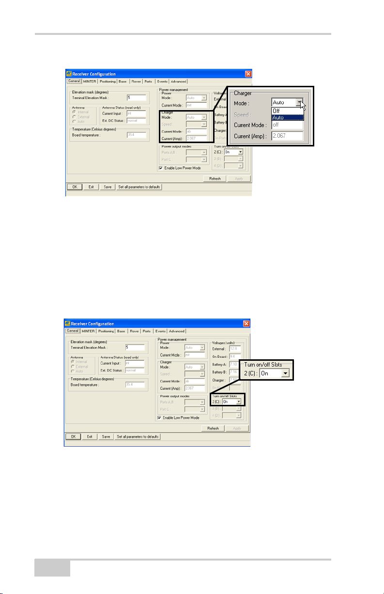
4. Select the Charger Mode drop-down list to set the desired charger
mode (Figure 2-10 on page 2-12). Current Mode displays the
charging battery: a, b, ab, or none (off).
• Off – receiver will not charge batteries
• Auto – receiver automatically detects and charges both
batteries
P/N 7010-0736
2-11
Page 50
Pre-survey Preparation
Figure 2-10. Select Charger Mode
5. Select the Turn on/off Slots drop-down list to set power output on
internal slots (Figure 2-11).
• On – slot C is powered if the receiver is turned on
• Off – internal slot will not be powered even if the receiver is
turned on
• Always – internal slot will be powered even if the receiver is
turned off
Figure 2-11. Select Power Output Modes – Ports and Slots
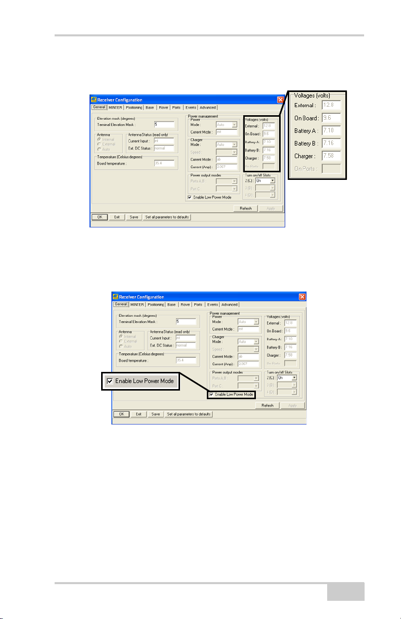
6. View the Voltages information (Figure 2-12 on page 2-13).
• External – displays the external power supply’s voltage
• On Board – displays the voltage drawn by the receiver board
• Battery A – displays the voltage of battery A
• Battery B – displays the voltage of battery B
2-12
GR-3 Operator’s Manual
Page 51
Power Management
• Charger – displays the charger’s output voltage during battery
charging
Figure 2-12. View Voltages Information
7. Select and check the Enable Low Power Mode check box to put
the receiver’s processor into low power consumption mode
(Figure 2-13).
Figure 2-13. Enable and Apply Power Settings
8. Click Apply.
P/N 7010-0736
2-13
Page 52

Pre-survey Preparation
Powering the Receiver
When powered from the internal batteries, the receiver will constantly
switch from one battery to the other, maintaining a difference of 0.4 V
between the batteries.
To check the status of the internal batteries, view the BATT LED
or check the status using available Topcon software.
• Check the BATT LEDs for battery status.
– A green light indicates greater than 85% charge.
– An orange light indicates an intermediate charge.
– A red light indicates less than 15% charge.
• Do one of the following using PC-CDU:
– Click on ConfigurationReceiver to view battery voltages
on the Receiver Configuration screen.
– Click on HelpAbout to view battery voltages on the About
PC-CDU screen.
Using the Detachable Batteries
The GR-3 receiver comes with two detachable, rechargeable batteries
and an AA battery shell. Each battery can provide up to between 4.5
and 8.5 (approximate) hours of operation at room temperature,
depending on the mode of the receiver and the capacity of the battery.
Table 2-1. Estimated Operating Times Using Two Fully-charged Batteries
Using the Detachable Batteries
Receiver conditions: Bluetooth = on; 10-12 SV tracked; room temperature
Modem off 17 hours
915+ modem in receive only mode 13 hours
915+ modem in 250mW transmission mode 11 hours
915+ modem in 1W transmission mode 9 hours
Using the Battery Shells and AA batteries
Receiver conditions: Bluetooth = on; 10–12 SV tracked
Modem off 2.5 hours
2-14
GR-3 Operator’s Manual
Page 53
Powering the Receiver
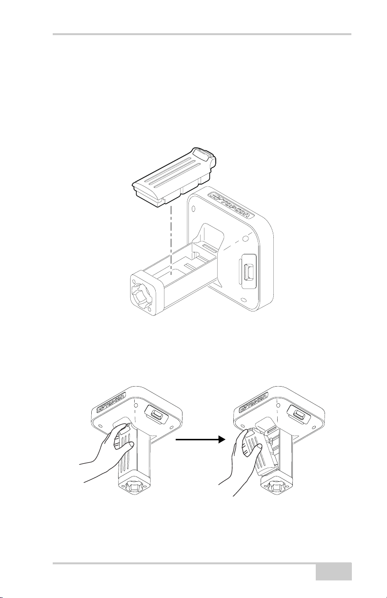
To attach the batteries (Figure 2-14):
1. With the battery slightly tipped, place the bottom of the battery
into the bottom of the battery pocket.
2. Gently push the top of the battery into the battery pocket until it
snaps into place. Make sure that the clip at the top of the battery
completely snaps into place.
Figure 2-14. Insert the GR-3 Batteries
To detach the batteries:
Using the clip at the top of the battery, gently pull down and out to
detach the battery from the receiver (Figure 2-15).
Figure 2-15. Detach the GR-3 Batteries
P/N 7010-0736
2-15
Page 54
Pre-survey Preparation
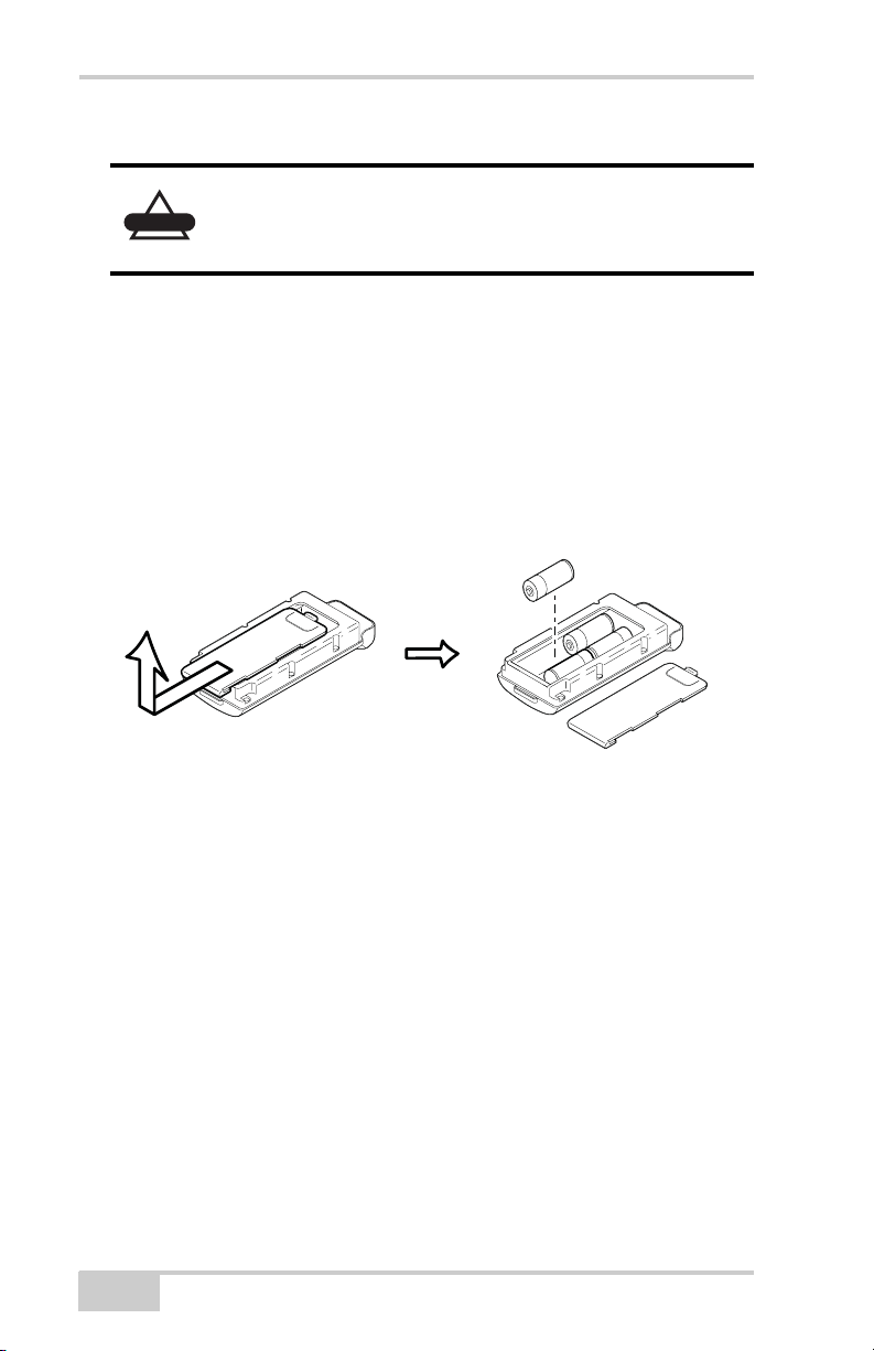
To assemble the AA battery shell (Figure 2-16):
Do not use rechargeable AA batteries.
CAUTION
Do not use the AA battery shell when the radio
modem is in transmitter mode.
1. Slide the back cover of the AA battery shell down and lift off.
2. Insert four AA batteries as shown on the inside of the shell (and
in Figure 2-16 below).
• The batteries on the left lay with the positive end towards the
bottom of the shell.
• The batteries on the right lay with the positive end towards
the top of the shell.
3. Replace the back cover of the shell.
+ -
+ -
- +
- +
Figure 2-16. Remove Cover and Insert AA Batteries
4. Insert the AA battery shell into the battery pocket of the receiver
as shown in “To attach the batteries” on page 2-15.
2-16
GR-3 Operator’s Manual
Page 55
Powering the Receiver
Using an Auxiliary Power Source
In addition to the attached batteries, the receiver connects to external
batteries. External batteries allow you to continue using the receiver
in case the internal batteries become discharged.
The batteries in the charging cradle will not charge
NOTE
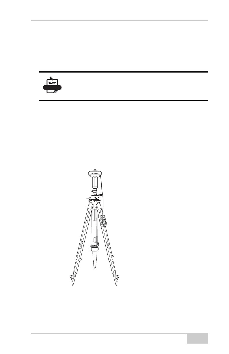
To connect the receiver and the charging cradle (Figure 2-17):
The charging cradle with extra batteries hooks onto a tripod or belt for
a convenient power supply for the receiver. The part number for the
receiver-to-charger cradle cable is 14-008072-01 or 14-008072-02.
1. Connect one end of the cradle-to-receiver cable to the charging
cradle.
2. Connect the other end to the power port on the receiver.
the internal/detachable batteries.
The charging cradle is used to power the receiver.
P/N 7010-0736
To recevier and
charging cradle
using receiverto-charger cable
Figure 2-17. Connect the Charging Cradle and Receiver
2-17
Page 56
Pre-survey Preparation
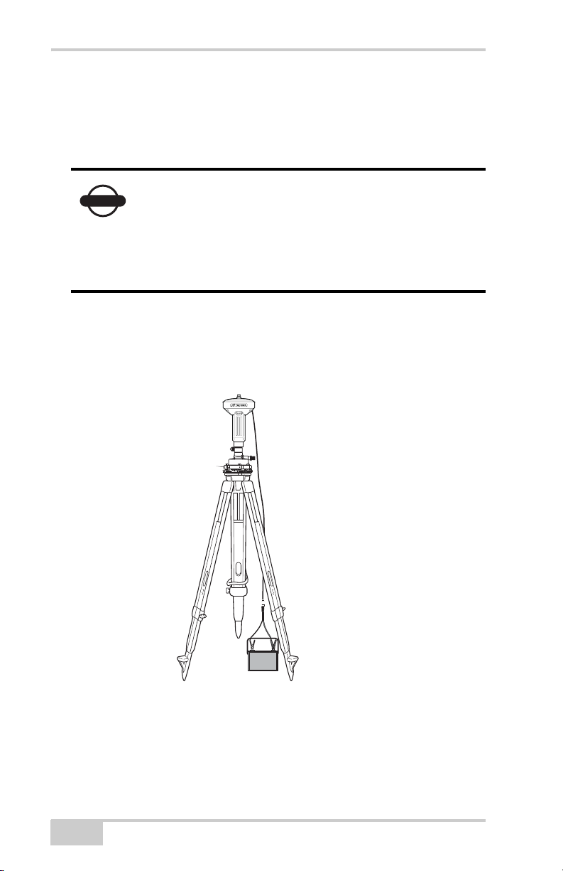
To connect the receiver to an auxiliary battery (Figure 2-18):
Use the ODU-to-alligator clips cable (p/n 14-008097-01LF) to
directly connect the auxiliary battery and the receiver’s power port
(without SAE).
When powering the receiver using external
NOTICE
batteries, set the charger mode to Off. Otherwise,
the detachable batteries will also charge, causing
operation time to decrease. See “Power
Management” on page 2-10 for more information
on setting the charger mode.
1. Connect the ODU-to-alligator clips cable to a 12-volt battery.
2. Connect the ODU-to-alligator clips cable to the receiver’s power
port.
3. Turn on the receiver.
From receiver to
auxiliary battery
using ODU-toalligator clips
cable.
Figure 2-18. Connect an Auxiliary Battery and the Receiver
A single external 12 V, 2.3 A*h battery should run the receiver and
modem for about 4.5 hours and the receiver for 6 hours.
2-18
GR-3 Operator’s Manual
Page 57

Connecting the Receiver and a Computer
Turning On/Off the Receiver
To turn ON the receiver, press and hold the power button until the
LEDs briefly flash.
To turn OFF the receiver, press and hold the power key for more than
one and less than four seconds (until both the STAT and the REC
LEDs are off). This delay (about 1 second) will prevent the receiver
from being turned off by mistake.
Connecting the Receiver and a
Computer
Topcon’s PC-CDU software provides an interface for various
configuration, monitoring, and management functions for the
receiver.
To configure, manage files, or maintain the receiver, connect the
receiver and a computer using one of the following methods and start
PC-CDU:
• a Bluetooth-enabled external device (computer/controller)
• an RS232 cable and a computer/controller
• a USB cable and a computer/controller with the TPS USB driver
installed
Once you have established a connection between the receiver and the
computer/controller, you will be able to configure the receiver and its
components, send commands to the receiver, download files from the
receiver’s memory; as well as, upload new firmware using
FLoader™, upload an OAF, and upload configuration files to a
receiver.
P/N 7010-0736
2-19
Page 58
Pre-survey Preparation
Establishing a Wireless Connection
The GR-3 receiver contains Bluetooth wireless technology that allows
file transfer and synchronization between the receiver and any other
external device that supports Bluetooth wireless technology; for
example, an FC-100, or a computer with USB-to-Bluetooth adapter or
PCMCA-to-Bluetooth adapter installed.
Changing the receiver’s Port D default settings will
NOTICE
The receiver and external device connection procedure varies slightly
depending on the type of external device used. In general, the
connection procedure is as follows.
affect the Bluetooth link. The default settings for
Port D are: 115200 bps, 8 data bits, 1 stop bit, no
parity, and no handshaking.
NOTICE
Refer to your Bluetooth-enabled external device
documentation for detailed connection information.
1. Turn on a Bluetooth-enabled external device and the receiver. The
default external device mode is Master; the receiver’s Bluetooth
module mode is Slave.
2. Instruct the external device (Master) to search for the receiver
(Slave).
3. Once the Master device detects the receiver, use the procedure
described in the external device’s documentation to connect it
with the receiver.
4. Connect to the desired configuration software (PC-CDU,
Modem-TPS, etc.) as described in the configuration sections.
If you cannot establish a connection, check that the receiver’s slot
three is enabled.
1. Connect your receiver and a computer using an RS232 cable or
USB cable and PC-CDU as seen below.
2. Click ConfigurationReceiverGeneral.
3. In the Turn on/off Slots area, ensure the Slot 2 (C) check box is
enabled.
2-20
GR-3 Operator’s Manual
Page 59

Connecting the Receiver and a Computer
Establishing an RS232 Cable Connection
1. Using the RS232 cable, connect the serial port of your computer
(usually COM1) to the receiver’s serial port.
2. Press the power buttons on the receiver and computer to turn
them on.
3. Connect to the desired configuration software (PC-CDU,
Modem-TPS, etc.) as described in the configuration sections.
Establishing a USB Connection
Make sure the computer has the TPS USB driver installed and that the
USB option is enabled.
1. Using the USB cable, connect the USB port of your computer to
the receiver’s USB port.
2. Press the power buttons on the receiver and computer to turn
them on.
3. Connect to the desired configuration software (PC-CDU) as
described in the configuration sections.
P/N 7010-0736
2-21
Page 60
Pre-survey Preparation
Bluetooth Module Configuration
Use BTCONF, Topcon’s Bluetooth module’s configuration program,
and your computer to:
• access the Bluetooth wireless technology module
• configure the Bluetooth module
• check or change the module’s configuration
To access the Bluetooth wireless technology module, first download
and install BTCONF, then connect your computer and the receiver
and run the configuration program. See “Installing BTCONF” on
page 2-4 for details.
Once you have BTCONF available, follow these steps to configure
the Bluetooth module.
1. Using the RS232 cable, connect the serial port of your computer
(usually COM1) to the receiver’s serial port. If needed, turn on
the receiver and computer.
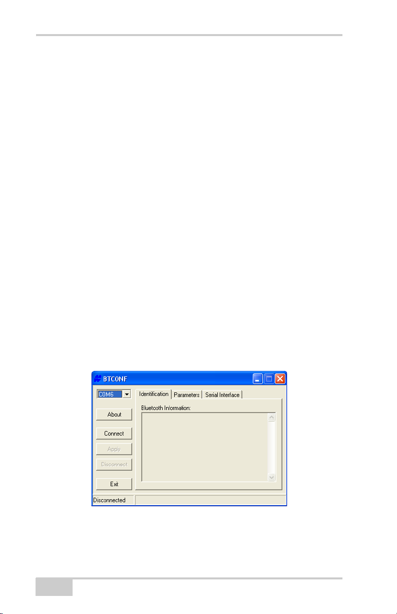
2. Run the Bluetooth module configuration program (Figure 2-19).
For BTCONF version and copyright information, click the About
button.
2-22
Figure 2-19. Bluetooth Module Configuration Main Screen
GR-3 Operator’s Manual
Page 61
Bluetooth Module Configuration
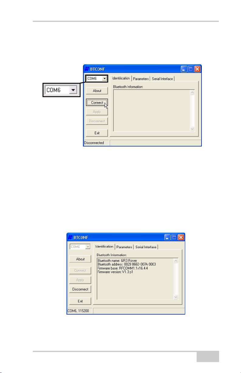
3. From the drop-down list in the upper left corner, select the
computer serial port used for communication (Figure 2-20).
4. Click Connect to connect the computer and Bluetooth module.
Figure 2-20. Select Communication Port and Click Connect
Once the receiver and computer connect through BTCONF, the
Identification tab (Figure 2-21) displays the following
information:
• Bluetooth name – the name of the Bluetooth module.
• Bluetooth address – the unique electronic address for the
module.
• Firmware version – the current firmware version of the
Bluetooth module.
Figure 2-21. BTCONF Identification Tab
The COM port and baud rate display in the lower left corner.
P/N 7010-0736
2-23
Page 62
Pre-survey Preparation
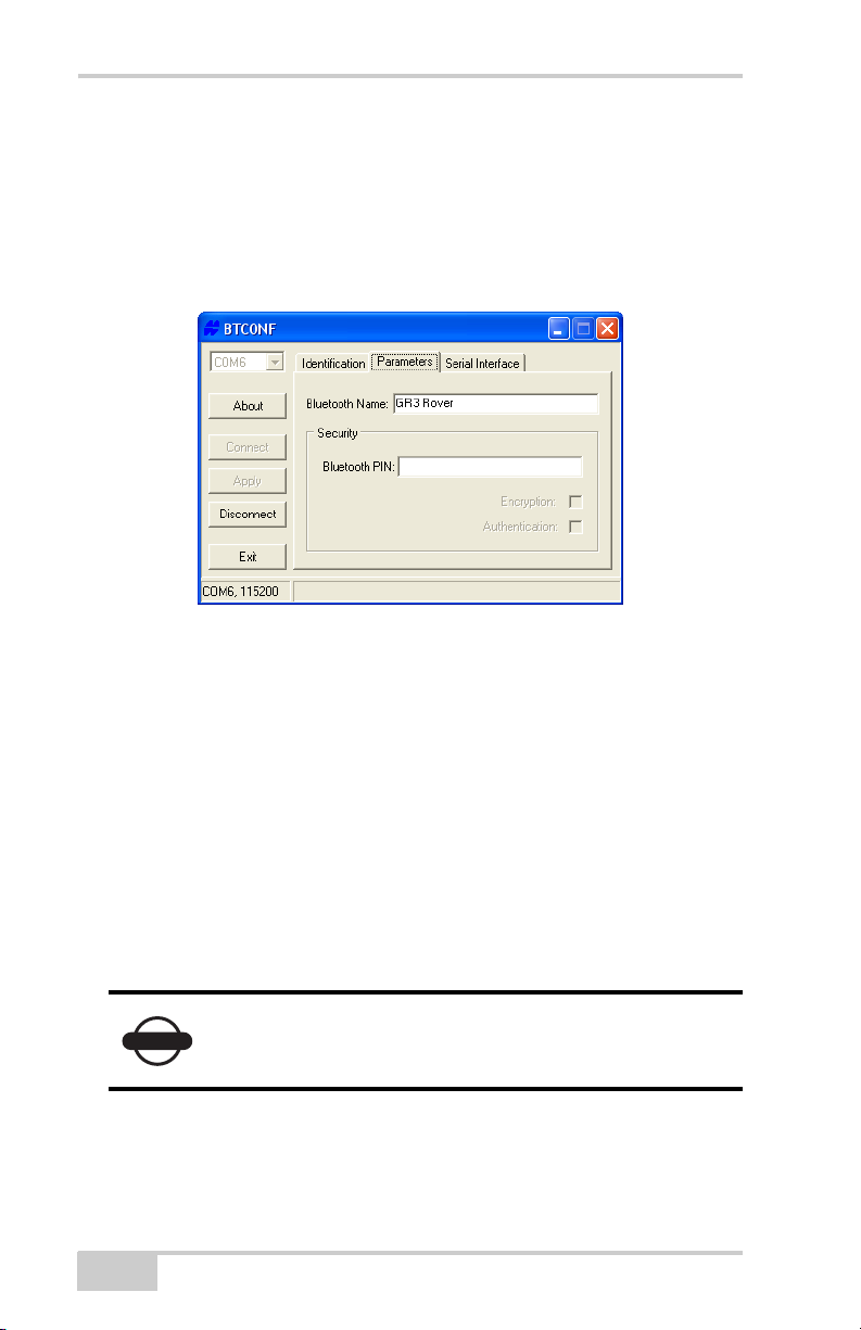
5. Click the Parameters tab (Figure 2-22). The Parameters tab sets
identifying and security information for your Bluetooth module.
The security section allows you to set data security and
unauthorized access parameters for the Bluetooth module.
6. Enter up to 14 characters to set a unique name for the Bluetooth
module (Figure 2-22), and click Apply.
Figure 2-22. BTCONF Parameters Tab
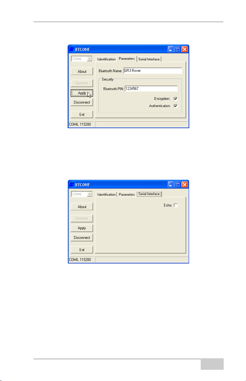
7. To set security parameters (Figure 2-23 on page 2-25), enter and
enable the following, then click Apply:
• Bluetooth PIN – enter up to 16 characters to specify a
personal identification number for the Bluetooth module.
• Encryption – enable to have the Bluetooth module encrypt
wirelessly sent data. To read encrypted data, the user must
have the same PIN used in the device that sent the data.
• Authentication – enable to require a PIN before two
Bluetooth enabled devices (such as, the receiver and a
computer) can establish a communication link. The two
devices must use the same PIN.
2-24
NOTICE
If you do not need security settings, leave these
parameters disabled.
GR-3 Operator’s Manual
Page 63
Bluetooth Module Configuration
Figure 2-23. BTCONF Security Parameters
8. Click the Serial Interface tab (Figure 2-24). Enable Echo to
display Bluetooth module replies and corresponding commands
on the computer terminal. If needed, click Apply.
9. Click Disconnect then Exit to quit BTCONF.
P/N 7010-0736
Figure 2-24. BTCONF Serial Interface Tab
2-25
Page 64

Pre-survey Preparation
Collecting Almanacs and Ephemerides
Each satellite broadcasts a navigation message that includes the
ephemeris parameters of the satellite, the almanac, and various other
information. The ephemeris parameters describe the orbital motion of
the satellite and are used to predict its location/trajectory. The
almanac gives the approximate orbit (course) for the transmitting
satellite and all other satellites in the same system only.
• GPS and GLONASS satellites broadcast ephemeris data
cyclically, with a period of 30 seconds.
• GPS satellites broadcast almanac data cyclically with a period of
12.5 minutes; GLONASS satellites broadcast almanac data
cyclically with a period of 2.5 minutes.
If the receiver has an almanac, you can considerably reduce the time
needed to search for and lock on to satellite signals.
The receiver regularly updates the almanac and ephemerides and
stores the most recent versions in its Non-Volatile Random Access
Memory (NVRAM).
1. Set up the receiver in a location with a clear view of the sky.
2. Turn on the receiver.
3. Wait for about 15 minutes while the receiver collects complete
almanac and ephemeris data from the satellites.
If 15 minutes have passed and the receiver does not
NOTICE
You will need to collect or update the almanac and ephemerides under
the following circumstances:
• If the receiver has been off for a long time.
• If the last known receiver position, stored in the NVRAM, is
different from the present position by several hundred kilometers.
• After loading a new OAF.
2-26
lock on to satellites, clear the NVRAM. See
“Clearing the NVRAM” on page 5-13 for details.
GR-3 Operator’s Manual
Page 65

• After loading new firmware.
• After clearing the NVRAM.
• Before surveying.
Collecting Almanacs and Ephemerides
P/N 7010-0736
2-27
Page 66

Pre-survey Preparation
Notes:
2-28
GR-3 Operator’s Manual
Page 67

Chapter 3
GR-3 Configuration
Both Base and Rover receivers must be configured according to the
desired survey method.
• In applications where real-time positioning results are required,
the Base receiver provides the correction information needed to
properly calculate the location of the Rover receiver.
A Base station is normally set up over a known point and collects
GPS/GLONASS data from satellites. As the receiver picks up
satellite data, it measures the carrier and code phases to
accurately compute and verify its location. Then, the receiver
transmits this information via radio (SS or GSM) to the Rover
receiver.
• The Rover receiver applies correction information from the Base
station to its current location to accurately calculate one or more
points.
Rovers are mobile GPS receivers on a survey pole or bipod that
compares the information from the Base station to the data it logs
from satellites and applies correction algorithms to accurately
calculate a new point.
• In applications intended for post-processing, the receivers
typically log code phase and/or carrier phase measurements
separately from common satellites and during the same time
interval. This data is then processed using post-processing
software (for example, Topcon Tools).
P/N 7010-0736
3-1
Page 68

GR-3 Configuration
When configuring receivers for RTK surveying, use the following
checklist to ensure the receivers are properly set up.
Perform pre-survey functions as described in Chapter 2.
Configure one receiver as an RTK Base station and the other
receiver as an RTK Rover. See “Configuring the Receiver” on
page 3-10.
Configure the communication data link for transmitting and
receiving corrections.
• For a Spread Spectrum modem, see “Configuring a Spread
Spectrum Radio Modem” on page 3-3.
• For a GSM/GPRS modem, see “Configuring a GSM Radio
Modem” on page 3-7.
Set up the Base receiver over a known point to begin collecting
static observation data and transmitting corrections. Set up the
Rover receiver to begin collecting RTK data. See “Receiver
Setup” on page 4-1 for more information.
When configuring receivers for post-processing surveying, use
the following checklist to ensure the receivers are properly set up.
Perform pre-survey functions as described in Chapter 2.
Configure one receiver as a Base station and the other receiver as
a Rover. See “Configuring the Receiver” on page 3-10.
Set up the Base receiver over a known point to begin collecting
static observation data. Set up the Rover receiver to begin
collecting static or kinematic observation data. See “Receiver
Setup” on page 4-1 for more information.
3-2
GR-3 Operator’s Manual
Page 69
Configuring the Radio Modem
Configuring the Radio Modem
Modem-TPS is Topcon’s radio modem configuration utility for
modems embedded in Topcon receivers. Modem-TPS provides the
following functions:
• Connecting a computer to an integrated radio modem via a serial
port or Bluetooth wireless technology.
• Displaying information about the radio modem installed in the
receiver.
• Programming the radio modem’s settings.
See the following sections for details on configuring the receiver with
a Spread Spectrum or GSM radio modem using Modem-TPS.
Note that the SS radio and the GSM radio do not
NOTICE
NOTICE
work simultaneously. Only one radio may be used
at a time.
When finished configuring the radio modem,
always disconnect from Modem-TPS before exiting
to prevent conflicts with serial port management.
Topcon’s configuration and surveying software, TopSURV or
Pocket-3D, also have the ability to configure Topcon receivers. Refer
to the TopSURV or Pocket-3D manuals for details.
Configuring a Spread Spectrum Radio Modem
For Topcon receivers, the integrated TPS FH915+ radio modem
provides TX/RX spread spectrum communications between a Base
and Rover. To configure a SS radio modem, have the following ready:
• Computer running Windows® 98 or newer
• Modem-TPS ver 2.0 or newer installed on the computer
• A serial cable (or Bluetooth wireless technology capabilities)
P/N 7010-0736
3-3
Page 70
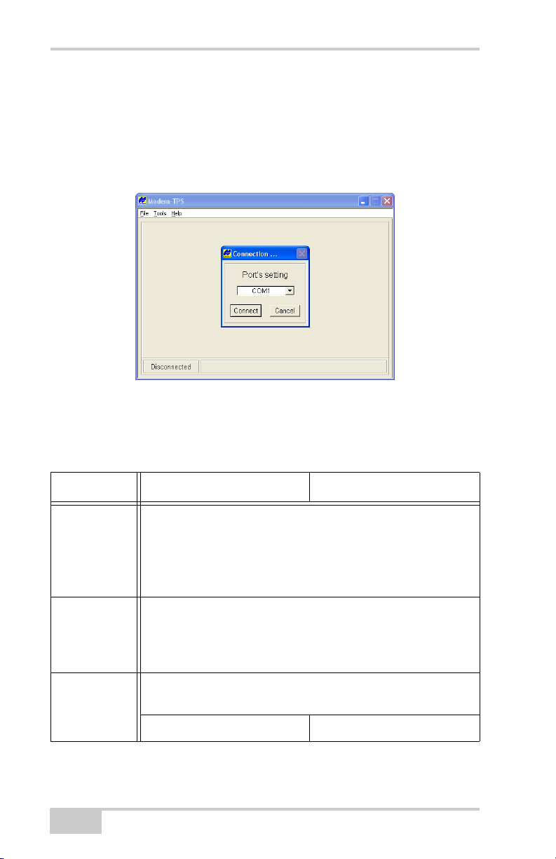
GR-3 Configuration
See “Configuring a GSM Radio Modem” to configure the GSM
portion of a spread spectrum radio setup.
1. Connect the computer and receiver. Turn on the receiver.
2. Open Modem-TPS and select the COM port the receiver is
connected to (Figure 3-1). Click Connect.
Figure 3-1. Connect to Modem-TPS
3. On the Radio Link tab, set the following parameters (Table 3-1)
and click Apply (Figure 3-2 on page 3-6).
Table 3-1. Receiver Parameters for the Radio Link Tab
Parameter Base Receiver Rover Receiver
Protocol Select either FH915 or FH915+ for the type of radio.
• An FH915 radio modem can be configured as a transmitter
or receiver.
• An FH915+ radio modem can be configured as a transmitter,
receiver, or repeater.
Location Select the country in which the receiver will be used.
If selecting “Australia”, the radio spectrum will be split in half
for compatibility with the available spectrum. This feature is
automatic and will be invisible to the user.
Operation
mode
3-4
Select Off if the radio is turned off; select Repeater if the radio
modem includes a feature to boost the signal.
Select Transmitter. Select Receiver.
GR-3 Operator’s Manual
Page 71
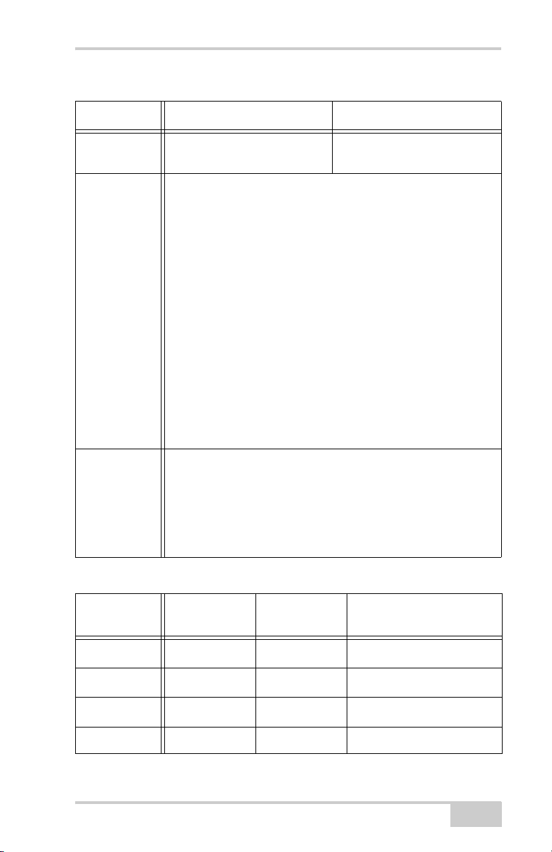
Configuring the Radio Modem
Table 3-1. Receiver Parameters for the Radio Link Tab (Continued)
Parameter Base Receiver Rover Receiver
Output power Select the transmission power
n/a
for the radio modem.
Link rate
Select the data transmission rate for the radio link.
As opposed to a baud rate (the rate of data transfer through a
serial cable interface), the link rate is the amount of data
For FH915+
protocol, the
link rate is
selected
automatically.
(measured in bits) the radio modem can transmit/receive over
the air in a specified time period (measured in seconds).
• 9600 – repeats data packet 3 times; packets are encoded to
decrease the affects of interference. This provides max. data
security, but reduces data throughput.
• 12000 – repeats data packets 5 times; no encoding is applied.
• 17000 – repeats data packets 3 times; no encoding applied.
• 24000 – only uses encoding.
• 51000 – uses no repeating or encoding. This provides max.
data throughput, but reduces data communication reliability.
For maximum efficiency, the data packet size transferred to the
radio modem in a given time should be equal to or less than the
link rate. Use Table 3-2 on page 3-5 to determine the link rate.
Channel Assign a channel on which to transmit/receive data. Each
channel uses a unique communication frequency, allowing up to
five simultaneously transmitting radio modems, without
interference, at the jobsite.
• Use the same channel for both receiver in the same network.
• Assign different channels to other networks.
Table 3-2. Link Rate vs. Baud Rate Comparison
Data packet
size (in bits)
0–9600 9600; 19200
9600–12000 19200; 38400
12000–17000 19200; 38400
TX serial baud
rate (bps)
Link rate
(bps)
a
;12000
9600
a
12000
; 24000
17000a; 24000
RX serial baud rate (bps)
9600; 19200; 38400; 57600
19200; 38400; 57600
19200; 38400; 57600
17000–24000 38400; 57600 24000 38400; 57600
P/N 7010-0736
3-5
Page 72
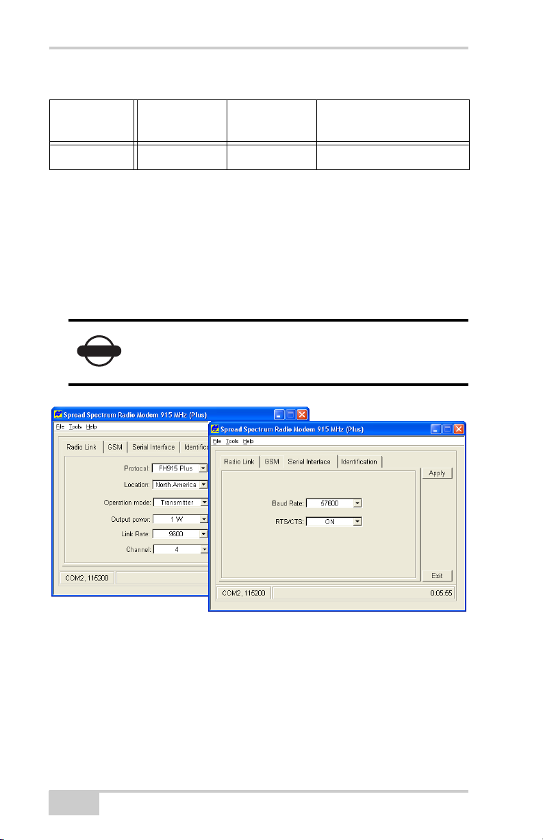
GR-3 Configuration
Table 3-2. Link Rate vs. Baud Rate Comparison (Continued)
Data packet
size (in bits)
24000–51000 57600 51000 57600
a. Recommended link rate for this data packet size.
TX serial baud
rate (bps)
Link rate
(bps)
RX serial baud rate (bps)
4. On the Serial Interface tab, select the following baud rate
parameters and click Apply (Figure 3-2).
• Baud Rate – select a baud rate for the modem’s serial port.
The same rate must be used for the receiver and the modem.
• RTS/CTS – controls the flow of data between the receiver and
modem. “On” enables handshaking/hardware flow control.
If the serial baud rate exceeds the link rate, enable
NOTICE
hardware handshaking to prevent the radio link
from overflowing, resulting in data loss.
Figure 3-2. Apply Radio Link and Baud Rate Parameters
5. When finished, click FileDisconnect.
3-6
GR-3 Operator’s Manual
Page 73
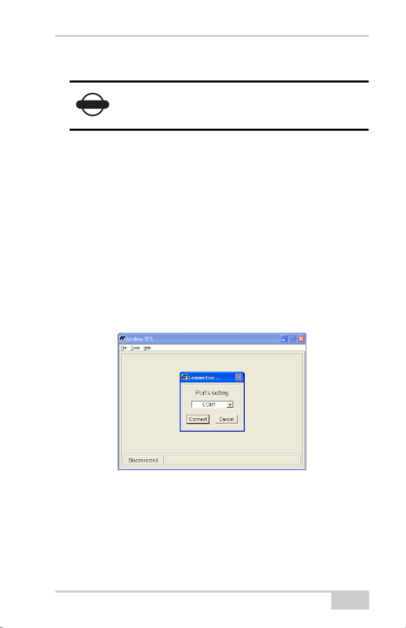
Configuring the Radio Modem
Configuring a GSM Radio Modem
To comply with RF exposure requirements,
NOTICE
For GR-3 receivers, the integrated TPS SS radio modem configured
with a GSM module provides TX/RX GSM communications between
a Base and Rover, or communication with a GPS network using IP
based connections. To configure a GSM radio modem, have the
following ready:
• Computer running Windows® 98 or newer
• Modem-TPS ver 2.0 or newer
• A serial cable (or Bluetooth wireless technology capabilities)
• The phone number of the base station
1. Connect the computer and receiver. Turn on the receiver.
2. Open Modem-TPS and select the COM port the receiver is
connected to (Figure 3-3). Click Connect.
maintain at least 25cm between the user and the
radio modem.
Figure 3-3. Connect to Modem-TPS
3. On the GSM tab, set the following parameters (Table 3-3 on
page 3-8) and click Apply (Figure 3-4 on page 3-8).
If some fields display “N/A”, click Refresh.
P/N 7010-0736
3-7
Page 74
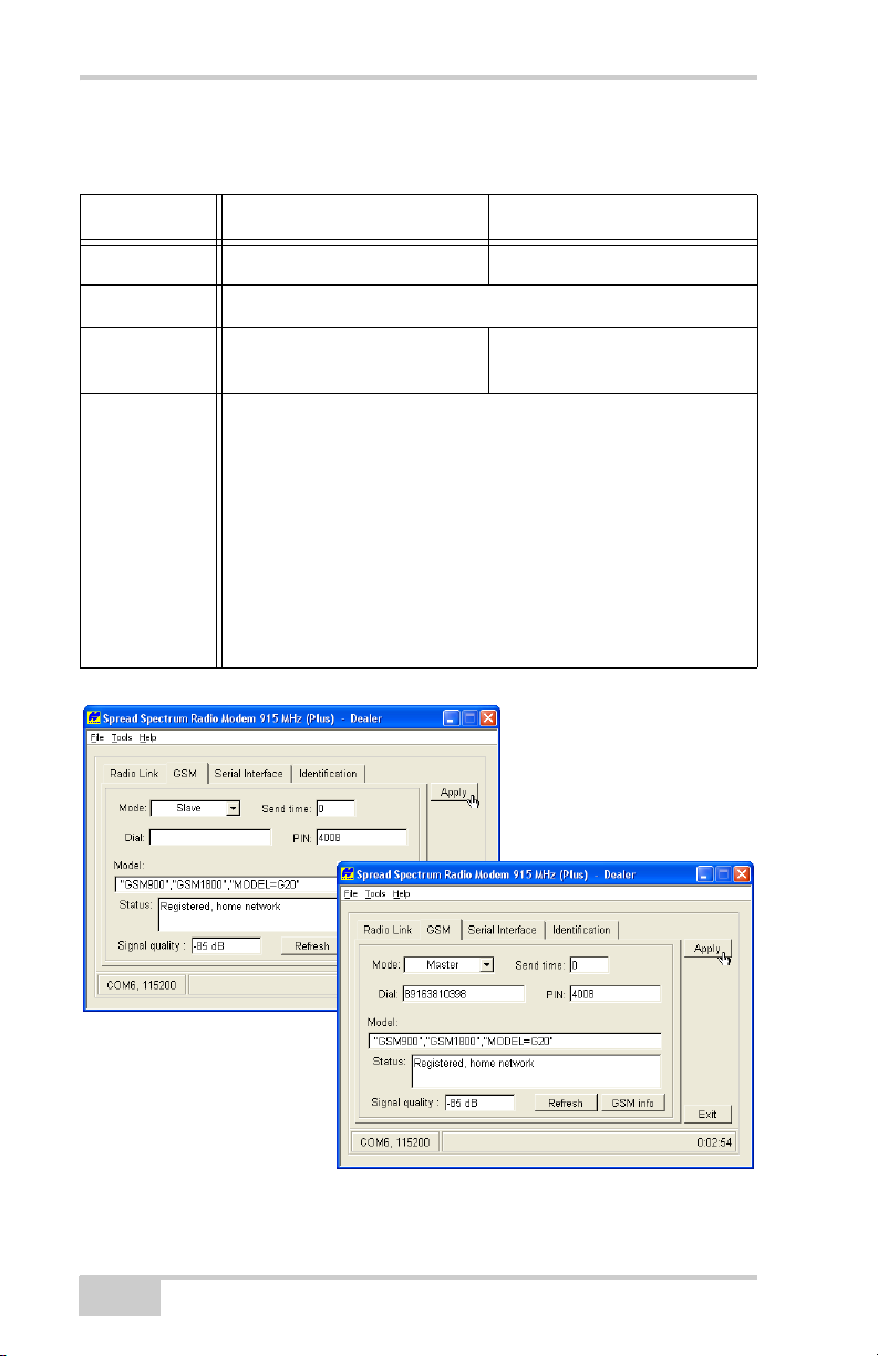
GR-3 Configuration
Table 3-3. Receiver Parameters for the FCS Tab
Parameter Base Receiver Rover Receiver
Mode Select Slave. Select Master.
PIN Enter a Personal Identification Number (PIN) if required.
Dial Leave blank. Enter the phone number of the
base GSM modem.
Send time Enter a period of time in seconds in which the base/rover GSM
modem will send a service word to the rover/base GSM modem.
• This parameter is used to maintain reliable communication
between a pair of modems and avoid unnecessary modem reinitialization.
• To ensure reliable and secure modem communication, this
parameter must be larger then the period for transmitting
differential corrections.
If the base and rover are both GR-3 receivers with internal GSM
modems, set the Send time to zero (0).
3-8
Figure 3-4. Select GSM Parameters for the Base and Rover
GR-3 Operator’s Manual
Page 75
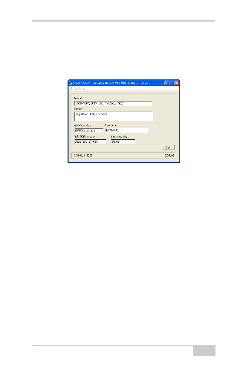
Configuring the Radio Modem
4. To view GSM modem information, click GSM info (Figure 3-5).
Click Quit to return to the GSM tab.
Signal quality is a reading of the strength of the GSM signal. The
lower the number—the closer to zero—the better the signal
quality. The minimum signal (cutoff) is -111db.
Figure 3-5. View GSM Information
5. On the Serial Interface tab, select a baud rate for the modem’s
serial port. The same rate must be used for both the receiver and
the modem.
6. Click Apply, then click FileDisconnect.
7. If needed, launch PC-CDU and set up the receiver to run as an
RTK Base station.
P/N 7010-0736
3-9
Page 76

GR-3 Configuration
Configuring the Receiver
The GR-3 can be configured in several ways for collecting data for
RTK or post-processing.
• A static Base station collects measurement information and saves
this data to its internal memory.
• An RTK Base station collects measurement information,
determines differential corrections, and transmits them to the
RTK Rover(s).
• A static Rover collects observation data from the same satellites
during the same time interval as the static Base station.
• An RTK Rover collects measurement information and accepts
corrections from the RTK Base station to compute its relative
position.
• A Rover acting as a repeater to re-transmit RTK Base station
measurements to other rover receivers, extending the range of a
GPS system.
To configure, manage files, or maintain the receiver, connect the
receiver and a computer using one of the following methods, and start
PC-CDU:
• use a Bluetooth-enabled external device (computer)
• use an RS232 cable
• use a USB cable and a computer with the TPS USB driver
installed (available on the TPS website)
PC-CDU is Personal Computer-Control Display Unit software used
to manage the various functions of your receiver. The full range of
PC-CDU configuration and function is outside the scope of this
manual. For more information on any of the procedures in this section
or on PC-CDU, refer to the PC-CDU User’s Manual available on the
TPS website.
PC-CDU configures the various parts of the receiver, saving the
settings in the receiver’s memory. These settings will be reflected
when you use the MINTER. The full range of PC-CDU configuration
and function is outside the scope of this manual.
3-10
GR-3 Operator’s Manual
Page 77
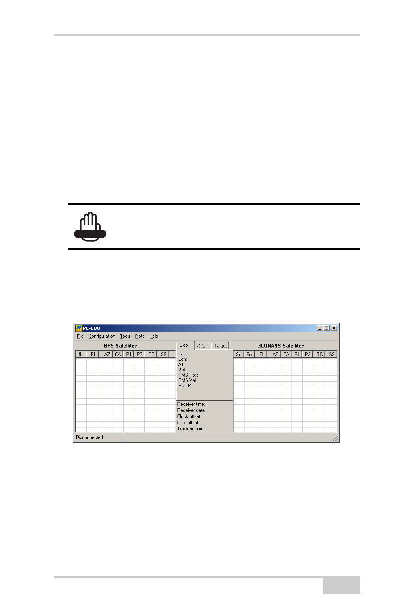
Configuring the Receiver
Once you have established a connection between the receiver and the
computer, you will be able to:
• configure the receiver and its components
• send commands to the receiver
• download files from the receiver’s memory
• load a new OAF and other configuration files to a receiver
The following Base and Rover configurations are recommended for
the most common applications. However, you can select
configuration parameters as needed for your particular jobsite.
Do not make other changes without consulting the
WARNING
PC-CDU Reference Manual.
1. Connect the receiver and computer as described in “Connecting
the Receiver and a Computer” on page 2-19.
2. Start PC-CDU on your computer. The PC-CDU main screen
displays (Figure 3-6).
Figure 3-6. PC-CDU Main Screen
Notice that the lower-left hand corner shows the receiver status as
“Disconnected”.
3. Click FileConnect.
P/N 7010-0736
3-11
Page 78
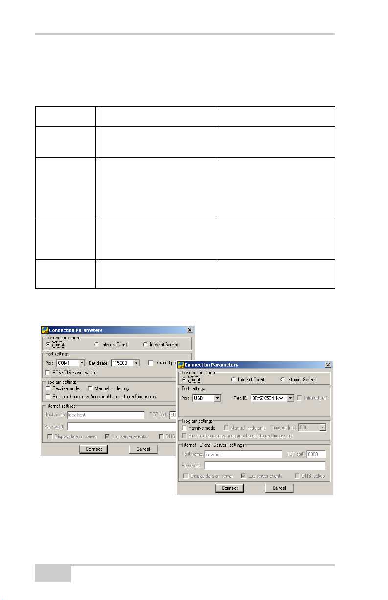
GR-3 Configuration
4. On the Connection Parameters dialog box, select the following
parameters (Table 3-4) and click Connect (Figure 3-7).
Table 3-4. Connection Parameters
Parameter RS232 or Bluetooth USB
Connection
Select Direct.
Mode
Port Select the port connecting the
Select USB
computer and receiver
(typically COM1, COM2 for
RS232 and COM3, COM4,
etc. for Bluetooth)
Baud Rate Select the communication rate
n/a
between the receiver and the
computer (usually 115200).
Rec ID n/a Select the receiver’s
identification number.
RS232 or Bluetooth
USB
3-12
Figure 3-7. Connection Parameters
GR-3 Operator’s Manual
Page 79
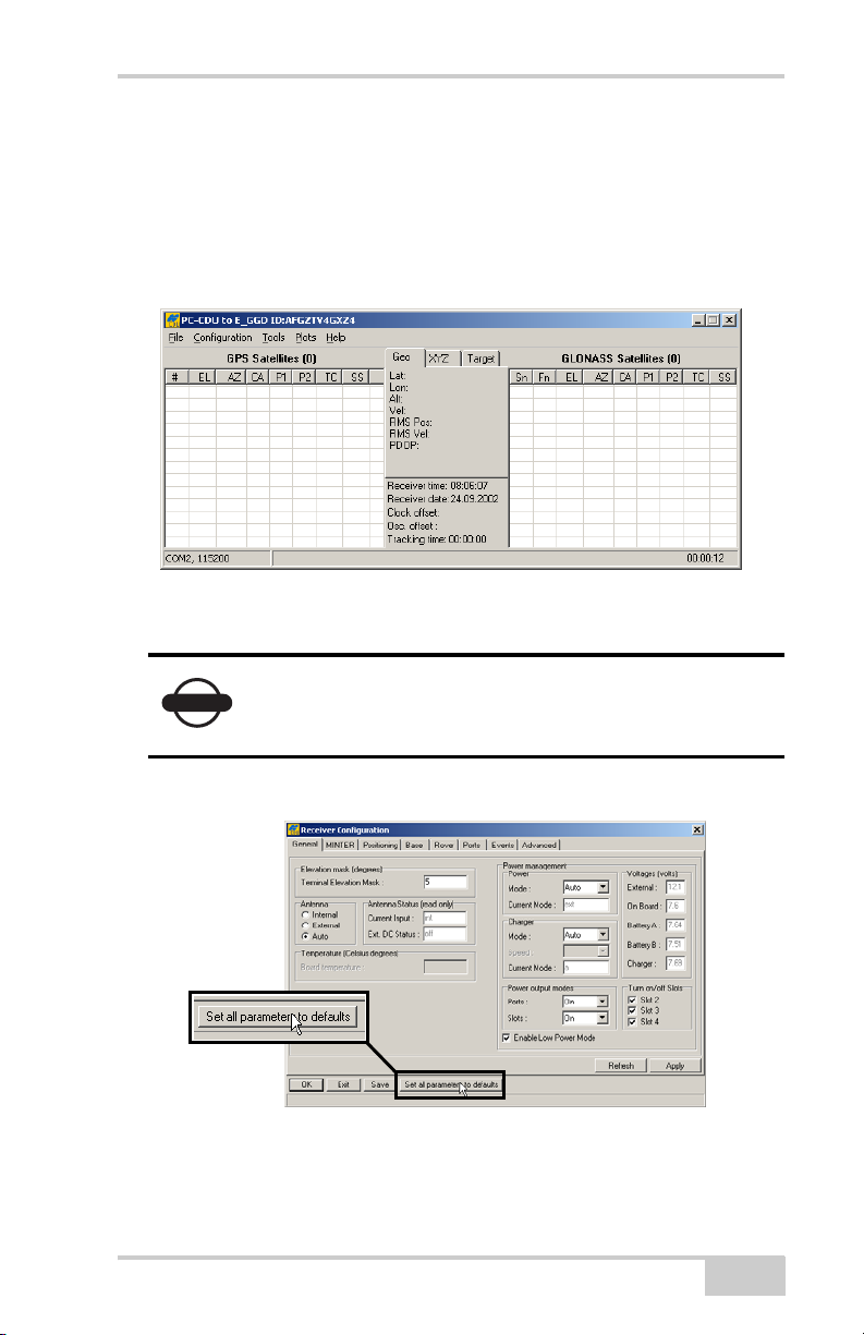
Configuring the Receiver
Once a PC-CDU connection with the receiver has been
established, the current communications settings—such as, port
name, baud rate (if applicable), and flow control (if applicable)—
display in the lower-left corner of the main window of PC-CDU.
A timer begins to count up in the lower-right corner as well
(Figure 3-8).
Figure 3-8. PC-CDU Connection Established
5. Click ConfigurationReceiver.
Click Apply after making any configuration
NOTICE
change; otherwise, the receiver will not register the
change.
6. Click Set all parameters to defaults (Figure 3-9).
Figure 3-9. Set All Parameters to Defaults
P/N 7010-0736
3-13
Page 80
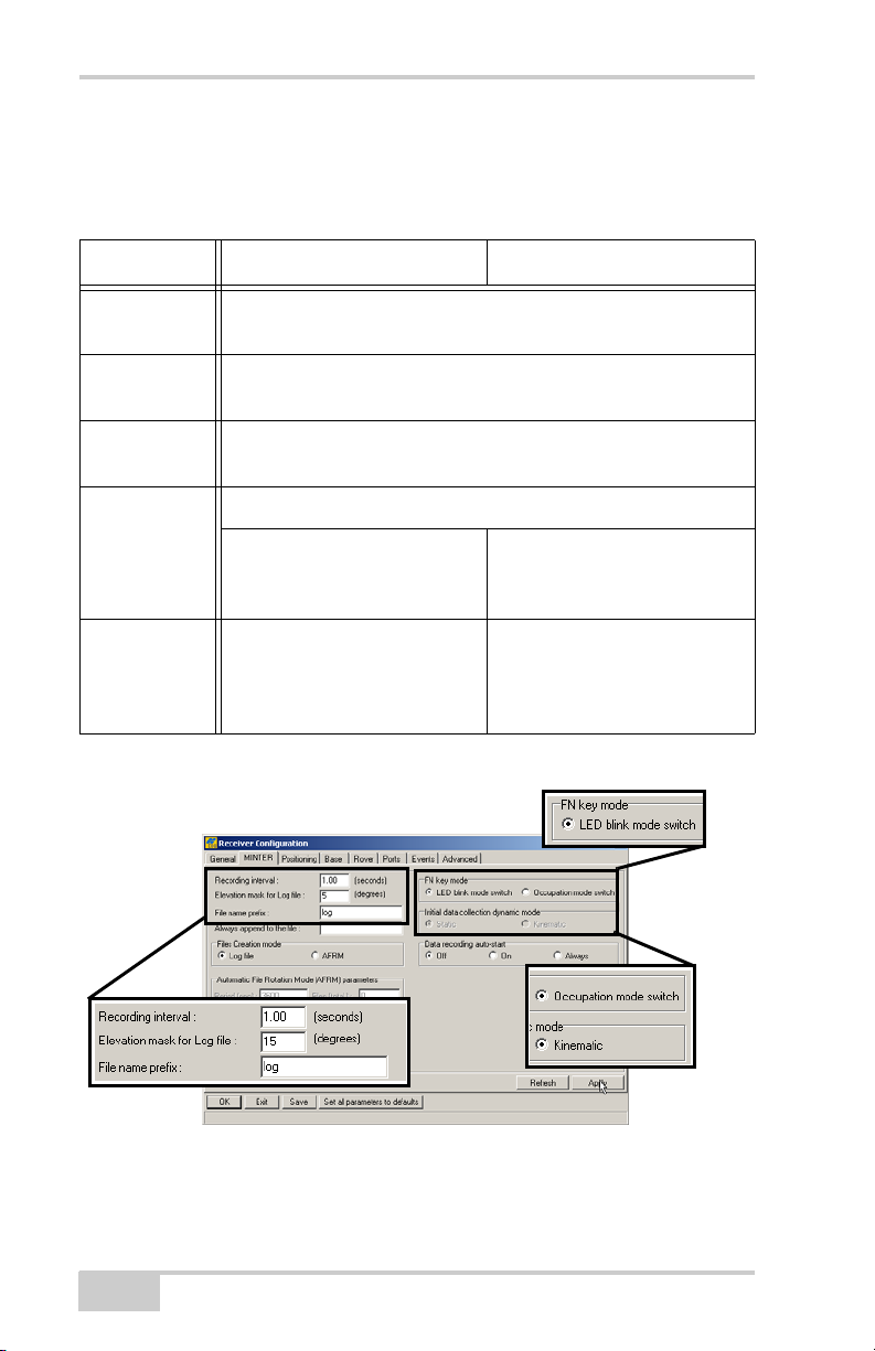
GR-3 Configuration
7. Click the MINTER tab and configure the following settings
(Table 3-5), then click Apply (Figure 3-10).
Table 3-5. Receiver Parameters for the MINTER Tab
Parameter Base Receiver Rover Receiver
Recording
Enter 15 seconds.
interval
Elevation
Enter 15 degrees.
mask angle
File name
prefix
Enter a unique ID, such as the last 3 digits of receiver’s serial
number.
FN key mode (starts/stops data recording using the FUNCTION key)
For Static data recording,
select LED blink mode switch.
For RTK data recording,
select Occupation mode
switch.
Initial data
collection
dynamic
n/a Select Kinematic.
(This setting is for trajectory
surveys.)
mode
RTK Rover
Static
Figure 3-10. Configure Receiver’s MINTER for Data Recording
3-14
GR-3 Operator’s Manual
Page 81
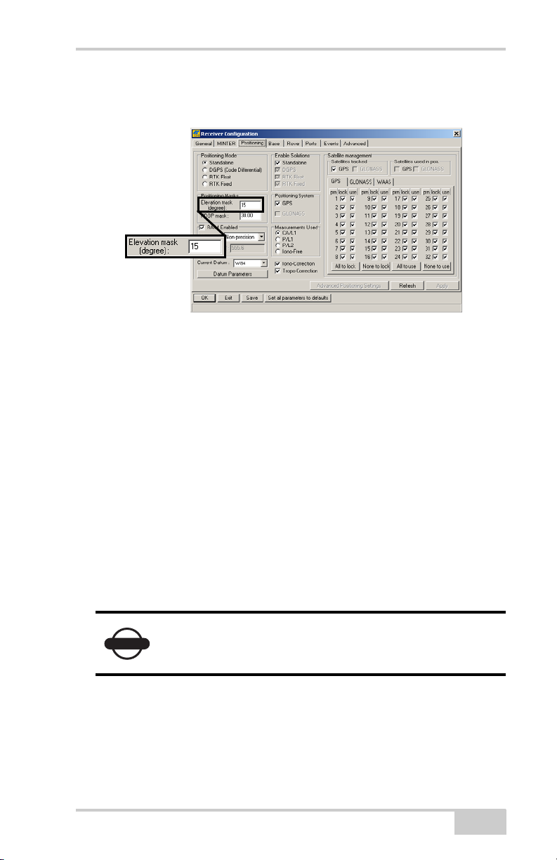
Configuring the Receiver
8. Click the Positioning tab and set the Elevation mask to 15
(Figure 3-11), then click Apply.
Figure 3-11. Configure Receiver Positioning – Elevation Mask
9. For the Base receiver, click the Base tab and set the following
parameters (Figure 3-12 on page 3-16), then click Apply.
• GPS/GLO at one time – enable
• Antenna position – enter Lat, Lon, and Alt values using one
of the following methods:
– If known, type in the values.
– Enable Averaged and enter the Averaged Span in seconds,
then click Apply. Click To ol sReset receiver and wait
until the specified interval (span) completes. Examine the
Base coordinates on the Base tab, they should correspond
to the coordinates obtained from the average. Click
Refresh if the coordinates are zeros.
– Click Get from receiver.
NOTICE
The reference geodetic coordinates specified on this
tab relate to the antenna L1 phase center.
Continue with step 11 on page 3-17 for RTK surveys or step 12
on page 3-18.
P/N 7010-0736
3-15
Page 82
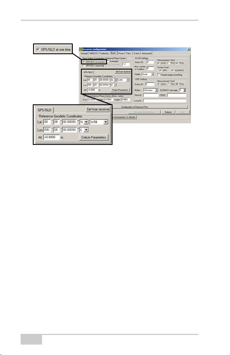
GR-3 Configuration
Figure 3-12. Base Configuration
10. For the Rover receiver, click the Rover tab and set the following
parameters, then click Apply (Figure 3-13 on page 3-17).
• Positioning Mode – For post-processed surveys, select
Standalone; for RTK surveys, select RTK float or RTK fixed.
• RTK Parameters, RTK mode – select either Extrapolation for
RTK float (kinematic) or Delay for RTK fixed (static).
– Extrapolation is for low-latency, high frequency output
(>= 5 Hz) RTK applications. The Rover will extrapolate
the Base station’s carrier phase measurement corrections
when computing the Rover's current RTK position.
This setting (extrapolation) is recommended.
– Delay is for 1 Hz high precision RTK applications. The
Rover RTK engine will compute either a delayed RTK
position (for the epoch to which the newly received
RTCM/CMR message corresponds) or the current standalone position (while waiting for new RTCM/CMR
messages coming from the base).
• RTK Parameters, Dynamics – select Static or Kinematic.
3-16
GR-3 Operator’s Manual
Page 83
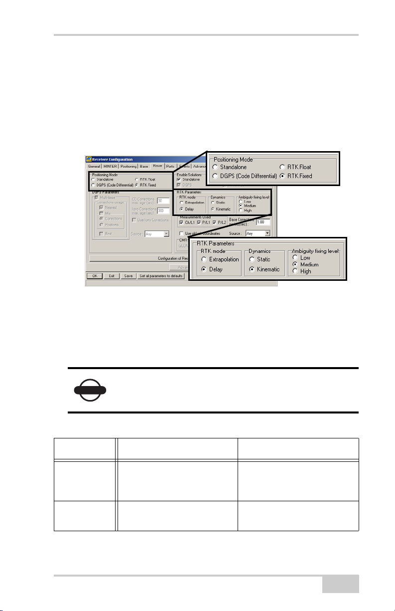
Configuring the Receiver
• RTK Parameters, Ambiguity fixing level – (not applicable to
RTK Float) select either Low, Medium, or High for indicator
states of 95%, 99.5%, or 99.9%, respectively. The RTK
engine uses the ambiguity fix indicator when making
decisions whether or not to fix ambiguities. The higher the
specified confidence level, the longer the integer ambiguity
search time.
Figure 3-13. Rover Configuration
Continue with step 11 for RTK surveys or step 12 on page 3-18.
11. For RTK surveys, click the Port s tab and set the following port
parameters for the serial port (Table 3-6), then click Apply
(Figure 3-14 on page 3-18).
NOTICE
Parameter Base Receiver Rover Receiver
Input n/a (Leave the default.) Select the same differential
Output Select the type and format of
P/N 7010-0736
For post-processed surveys, keep the default values
for these parameters.
Table 3-6. Receiver Parameters for the Ports Tab
correction format selected for
the Base.
Select “None”.
differential corrections.
3-17
Page 84
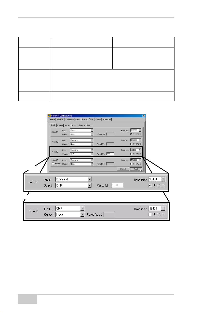
GR-3 Configuration
Table 3-6. Receiver Parameters for the Ports Tab (Continued)
Parameter Base Receiver Rover Receiver
Period (sec) Enter the interval at which the
receiver will transmit
differential corrections.
Baud rate Select a baud rate to use for transmitting differential messages
from the receiver board to the modem module
The baud rate must match the modem’s serial port speed.
RTS/CTS Select to enable handshaking.
Base
Rover
n/a (Leave the default.)
Figure 3-14. Base and Rover Configuration for RTK Surveys – Ports
12. Click the Advanced tab and then the Multipath tab. Set the
following parameters and click Apply (Figure 3-15 on
page 3-19).
• Code multipath reduction – enable
• Carrier multipath reduction – enable
3-18
GR-3 Operator’s Manual
Page 85
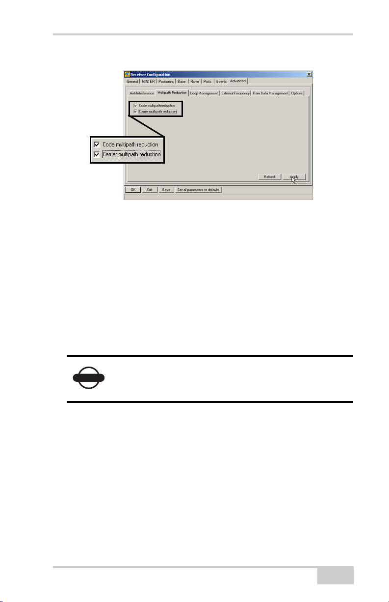
Configuring the Receiver
Figure 3-15. Configure Mulitpath Parameters
13. Click OK to save the settings and close the dialog box.
Once the receiver is configured, the configuration will remain
until you change it using PC-CDU/TopSURV/Pocket-3D or
clearing the NVRAM.
For more details on the settings available for configuring the Base
and Rover receivers, refer to the PC-CDU Reference Manual.
14. Continue with other configuration activities or click File
Disconnect, then FileExit to quit PC-CDU. Disconnecting
before exiting ensures proper port management.
NOTICE
P/N 7010-0736
Disconnect the receiver from PC-CDU before
exiting to eliminate possible conflicts with the
management of the computer’s serial ports.
3-19
Page 86
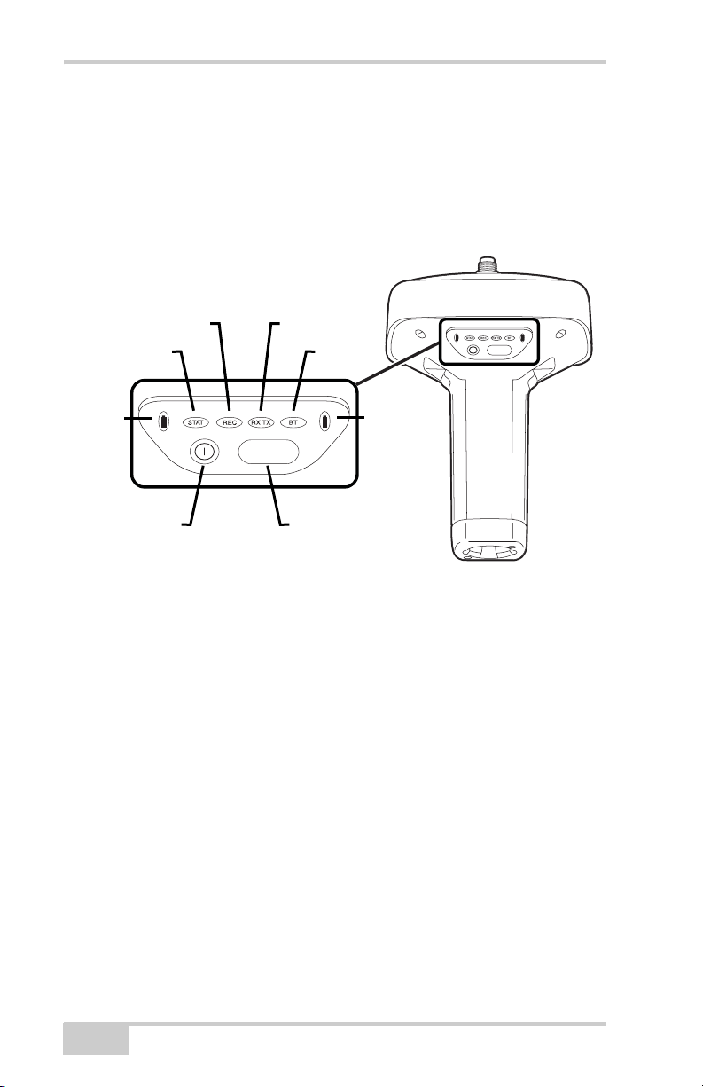
GR-3 Configuration
MINTER Configuration
The Minimum INTERface (MINTER) consists of two keys (power
and FUNCTION) that control the receiver’s operation, four LEDs
(STAT, REC, RX/TX, and BT) that display the receiver’s operational
status, and two LEDs that display the battery status (Figure 3-16).
REC RX TX
STAT
BT
FUNCTION
Battery
Power
Button
FUNCTION
FUNCTION
Button
Figure 3-16. MINTER
Battery
The MINTER performs the following functions. For more
information on using the MINTER, see “MINTER Operation” on
page 4-7.
• Turns the receiver on or off; puts it in Sleep mode.
• Turns data recording on or off (FUNCTION button).
• Changes the receiver’s information mode.
• Shows the number of GPS (green) and GLONASS (orange)
satellites being tracked (STAT LED).
• Shows the data recording status (REC LED).
• Shows each time data is recorded to internal memory (REC
LED).
• Shows the status of post-processing mode (static or dynamic)
when performing a Post-Processing Kinematic survey with the
help of FN key (REC LED).
3-20
GR-3 Operator’s Manual
Page 87
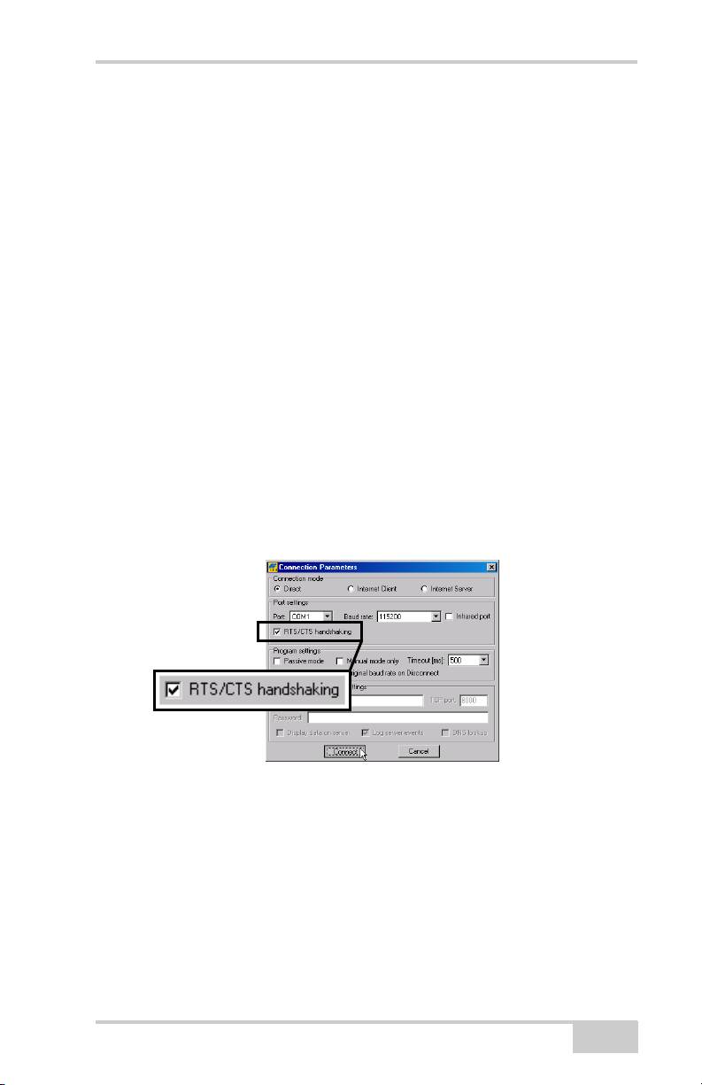
MINTER Configuration
• Shows the status (high charge, intermediate charge, or low
charge) of the battery (BATT LED).
• Shows the power status for the receiver (BATT LED).
• Shows the status of the modem and if it receives signals (TX RX
LED).
• Shows Bluetooth activity (BT LED).
Use PC-CDU to configure MINTER settings. The procedure below
describes the most common settings; refer to the PC-CDU Reference
Manual for other possible MINTER configurations.
1. Connect your receiver and computer. See “Connecting the
Receiver and a Computer” on page 2-19 for this procedure.
2. On the PC-CDU Main window, click FileConnect.
3. On the Connection Parameters dialog box, enable RTS/CTS
handshaking (Figure 3-17).
See “Connecting the Receiver and a Computer” on page 2-19 for
details on setting other parameters.
4. Click Connect.
Figure 3-17. Connection Parameters – MINTER Settings
5. Click ConfigurationReceiver then click the MINTER tab, set
the following parameters and click Apply (Figure 3-18). See the
following pages for descriptions of these parameters.
• Recording interval on page 3-22
• Elevation mask for log file on page 3-22
• File name prefix on page 3-22
• Always append to the file on page 3-23
P/N 7010-0736
3-21
Page 88
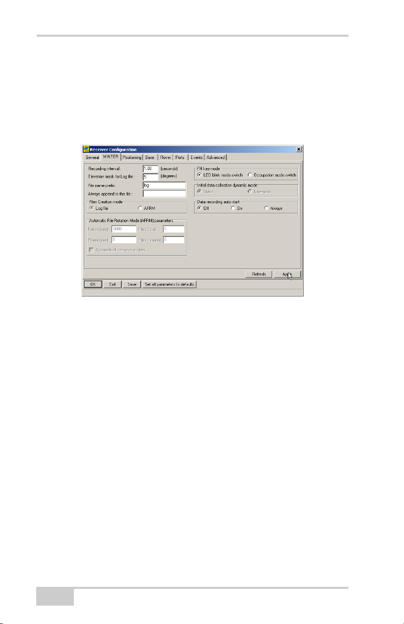
GR-3 Configuration
• Files Creation mode on page 3-23
• Automatic File Rotation Mode (AFRM) on page 3-23
• FN key mode on page 3-24
• Initial data collection dynamic mode on page 3-25
• Data recording auto-start on page 3-25
Figure 3-18. Receiver Configuration – MINTER Tab
Recording Interval parameter This parameter specifies the logging
rate of the log file when the MINTER FUNCTION button (pressed
for 1–5 seconds) activates data logging. This setting is used for both
logging a single log file and logging receiver data in AFRM mode.
Values are 1–86400 seconds. The default value is one second.
Elevation Mask for Log File parameter This parameter specifies the
minimum elevation angle for the satellites whose data will be put in
the receiver files logged when pressing FUNCTION. The default
value is five degrees.
File Name Prefix parameter This parameter specifies the prefix
added to the names of receiver files created when pressing
FUNCTION. The prefix can be up to 20 characters long. The default
value for the Name Prefix is “log”.
Log file names have the following structure:
<prefix><month><day><sequential alphabet letter>
3-22
GR-3 Operator’s Manual
Page 89

MINTER Configuration
The file name depends on both the file creation time (month and day)
and additional letter suffixes to avoid confusion between files created
on the same day.
Always Append to the File parameter If you want new receiver
data to be appended to an existing log file, enter the desired file name
in this parameter. The setting can be up to 20 characters long.
Files Creation Mode parameter This parameter has the following
operation modes:
• Log file – If the log file radio button has been selected, pressing
the FUNCTION button closes the current log file. If data logging
is off, pressing FUNCTION opens a new log file.
• AFRM – If AFRM radio button has been selected, pressing
FUNCTION enables this mode. If AFRM has been enabled,
pressing FUNCTION disables this mode.
Automatic File Rotation Mode (AFRM) parameters TPS receivers
are capable of automatically rotating log files. During a “file rotation”
event, the receiver closes the current file and opens a new one
according to a user-defined schedule. The Period and Phase
parameters specify this schedule. File rotation launches the moment
the receiver time module Period is equal to Phase. More precisely, a
new log file opens immediately before the scheduled epoch causing
data tagged with this epoch to be recorded to the new log file.
When opening a new log file, the receiver enables the default set of
messages output with the default output period. Both the default set of
messages and the default output period are programmable.
• Period – specifies the time duration of each log file created in
AFRM mode. Values are 60 to 86400 seconds; default value is
3600 seconds.
• Phase – specifies the “phase” (constant time shift) of creating
multiple log files in AFRM mode. Values are 0 to 86400 seconds;
default value is zero seconds.
• Files (total) – a counter that specifies how many multiple log files
must be created in AFRM until this mode automatically turns off.
This counter decrements on every file rotation until it value
P/N 7010-0736
3-23
Page 90

GR-3 Configuration
becomes zero, then file rotation automatically stops. The counter
initializes with AFRM.
Note that a log file opens immediately after turning AFRM on.
This startup file is not considered a file rotation event; the AFRM
counter will not decrement.
31
Values are 0 to [2
-1]; default value is 0 (zero). Zero means that
an unlimited number of log files will be created.
NOTICE
The receiver’s memory holds up to 512 files.
• Files (remain) – specifies the number of files left for the receiver
31
to create in AFRM. Values are 0 to [2
-1]; default value is zero.
• Automatically remove old files – when no free memory is
available to log data, automatically removes the earliest log file. If
this parameter is enabled, your receiver will erase the file with the
earliest file creation time/date. AFRM must be enabled to use this
FIFO (First-In, First-Out) feature. The default value is off
(disabled).
FN Key Mode parameter Use these two radio buttons to program
how the receiver will react when pressing the FUNCTION key.
• LED blink mode switch – pressing FUNCTION will toggle
between the MINTER’s normal/extended information modes and
start/stop data recording of Static survey.
– FUNCTION pressed for less than 1 second: changes the
information mode (Normal or Extended Information Modes).
– FUNCTION pressed for 1 to 5 seconds: starts or stops data
recording (Static post-processing mode).
• Occupation mode switch – pressing FUNCTION (less than one
second) will insert into the corresponding log file a message
indicating that the survey type has been changed from static to
kinematic, or vice versa. If the REC LED blinks green, the
current mode is dynamic, if it blinks orange, the current mode is
static. For more details, see Table 1-2 on page 1-14 and refer to
the PC-CDU Reference Manual.
3-24
GR-3 Operator’s Manual
Page 91

MINTER Configuration
Initial Data Collection Dynamic Mode parameter These radio
buttons specify the starting occupation type descriptor inserted at the
beginning of receiver files logged. Select Static or Kinematic to
specify that the corresponding log file will start with a static (STOP)
or kinematic (GO, Trajectory) occupation, respectively.
Data Recording Auto-start parameter These radio buttons allow
you to program your receiver’s behavior in the event of a power
failure.
Table 3-7 describes the different scenarios available and the results
after power is restored to the receiver. “Specified file” refers to the file
name entered in the Always append to file field.
Table 3-7. Data Recording Parameter Behavior
Before Power
Failure
Receiver data
logged to file
specified.
Receiver data
logged to
default file.
File specified;
receiver data
logging not
started.
No file
specified;
receiver data
logging off.
Enabled Radio Button Results
Off On Always
Data logging will
not resume when
power is restored.
Data logging will
not resume when
power is restored.
No file will open
with this name.
Data logging will
not start when
power is restored.
Data logging will
not start when
power is restored.
Receiver will
resume data
logging to the
same file when
power is restored.
A new log file will
open when power
is restored and
data will log to
this file.
No file will open
with this name.
Data logging will
not start when
power is restored.
Data logging will
not start when
power is restored.
Receiver will resume
data logging to the
same file when power
is restored.
A new log file will
open when power is
restored and data will
log to this file.
A log file with this
name will open and
data logging will start
after power is
restored.
A log file with a
default name will
open and data logging
will start after power
is restored.
P/N 7010-0736
3-25
Page 92
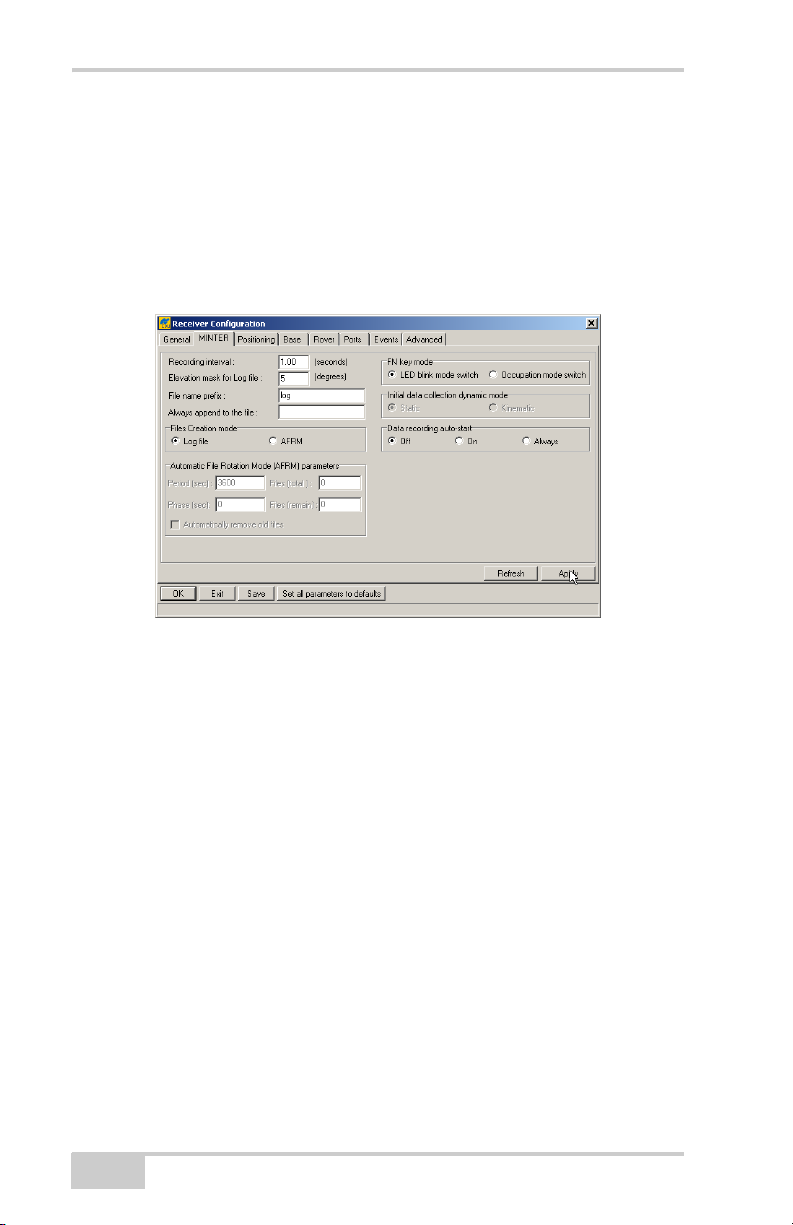
GR-3 Configuration
Also, if Always is enabled, the receiver will automatically start
logging data (to a newly created or an existing file) in the following
three cases:
• After turning on the receiver using the power button.
• After resetting the receiver (using PC-CDU).
• After taking the receiver out of Sleep Mode.
Figure 3-19. MINTER Tab
3-26
GR-3 Operator’s Manual
Page 93

Chapter 4
GR-3 Receiver Setup
and Survey
After configuring the receivers for surveying, each receiver needs to
be setup up and the receiver’s height measured and the survey can
begin. The MINTER provides quick access for logging data,
changing receiver modes, and viewing general data logging and
satellite information during a survey.
Receiver Setup
A typical GPS survey system consists of a Base station set up over a
known point and a Rover receiver set up to be a mobile data collector.
After setting up the Base and Rover receivers, the antenna height
must be measured.
Before collecting data, make sure the Base and Rover receivers
contain a current almanac and current ephemeris data (see “Collecting
Almanacs and Ephemerides” on page 2-26).
Step 1: Set up the Receivers
The Base station must be set up, logging data, and transmitting data
before setting up the Rover receiver. Receiver setup for either postprocess or RTK surveys is the same.
Set up the Base station and its components.
See “To set up the Base receiver” on page 4-2 for details.
Set up the Rover receiver.
See “To set up the Rover receiver” on page 4-3 for details.
P/N 7010-0736
4-1
Page 94
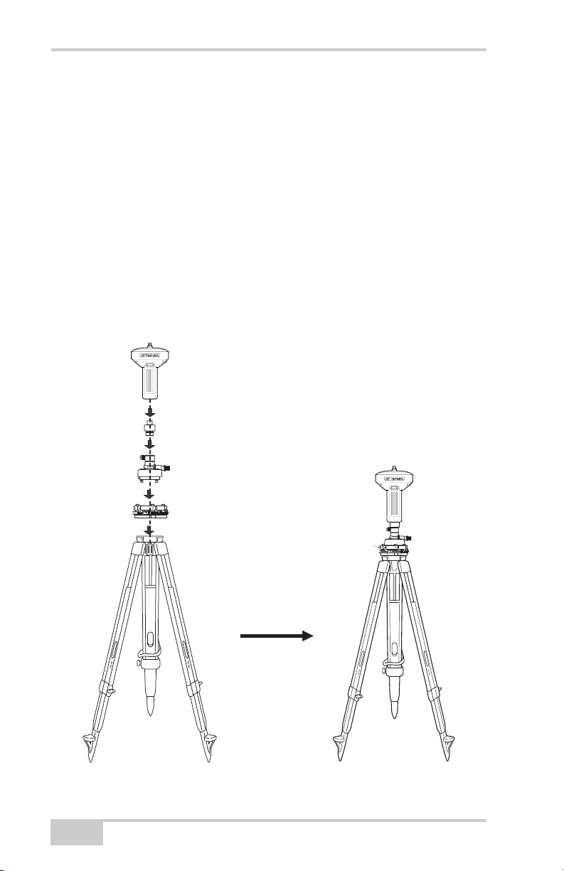
GR-3 Receiver Setup and Survey
To set up the Base receiver (Figure 4-1):
1. Install a tripod over a known control point.
2. Secure the universal tribrach to the tripod. Place the tribrach
adapter (either universal or precision) on the tribrach and tighten
the screws.
3. Insert the L-plug (horizontal spacer) into the precision tribrach
adapter.
4. Attach the GR-3 receiver to the tribrach adapter. Attach the
desired antenna to the modem antenna connector.
5. Carefully level the tripod and tighten the screws.
6. Attach any other accessories as needed (for example, a backup
power supply).
GR-3 Receiver
Horizontal Spacer
4-2
Tribrach Adapter (Precision)
Universal Tribrach
Figure 4-1. Install Tripod and Receiver over Control Point
GR-3 Operator’s Manual
Page 95
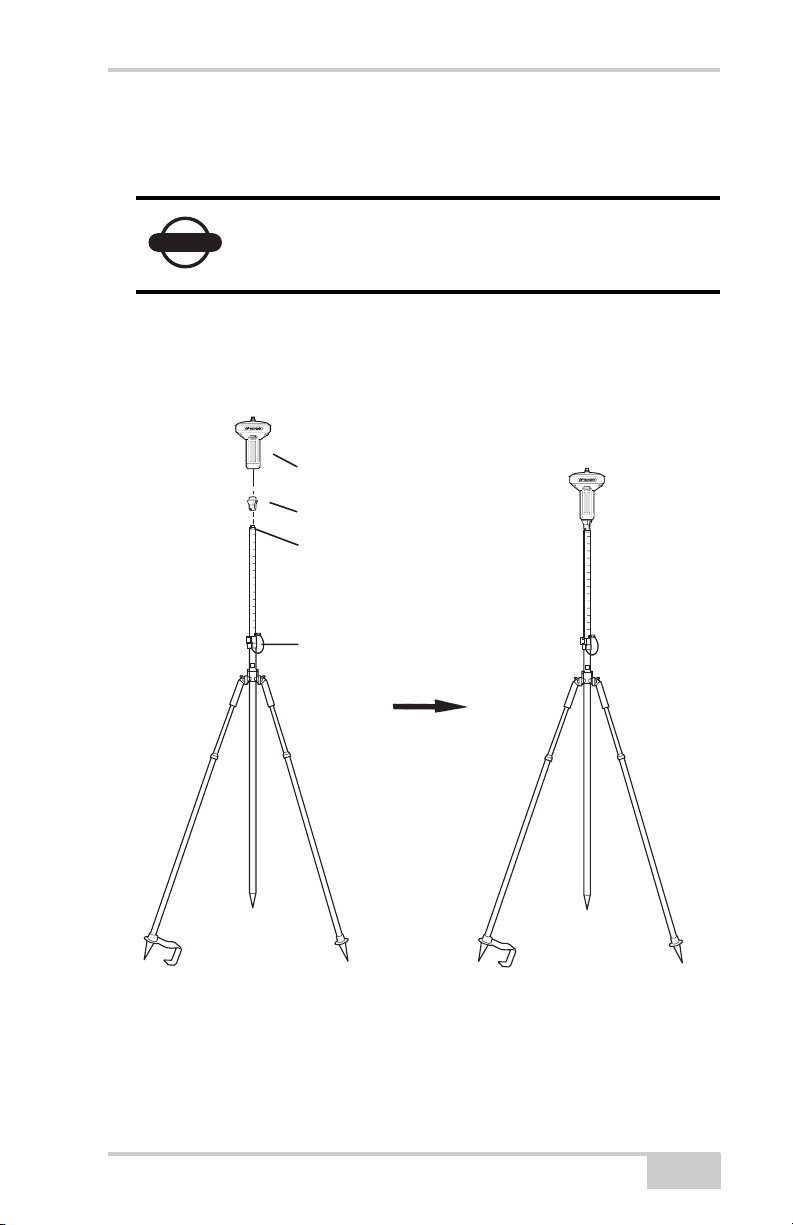
Receiver Setup
To set up the Rover receiver (Figure 4-2):
1. If needed, attach the quick disconnect to the bipod/range pole.
Use a bipod during post-process surveys to ensure
NOTICE
the antenna/receiver remains unmoving during data
logging.
2. Attach the GR-3 receiver to the quick disconnect. Make sure the
receiver locks into place.
3. Attach the desired antenna to the modem antenna connector.
GR-3 Recevier
Quick disconnect
5/8 inch screw
P/N 7010-0736
Lock
Figure 4-2. Connect GR-3 Receiver to Bipod
4-3
Page 96

GR-3 Receiver Setup and Survey
Step 2: Measure Antenna Height
The location of the antenna relative to the point being measured is
very important for both surveys in which the elevation of the points is
important and in surveys for horizontal location only. Horizontal
surveys are often larger in area than can reliably fit on a flat plane,
therefore the antenna adjustment must be done in three dimensions
and then projected onto a two dimensional plane.
The receiver calculates the coordinates of the antenna’s phase center.
To determine the coordinates of the station marker, the user must
specify the following:
• Measured height of the antenna above the station marker
• Method of measuring the antenna height
• Model of the antenna used
Antennas have two types of measurements:
• Vertical – measured from the marker to the antenna reference
point (ARP) located on the bottom of the receiver at the base of
the mounting threads.
• Slant – measured from the marker to the lower edge of the
antenna slant height measure mark (SHMM) located on both end
panels of the receiver.
The point to which surveying with GPS/GLONASS measures is
called the Phase Center of the antenna. This is analogous to the point
at which a distance meter measures in a prism. A user must enter the
prism offset to compensate for this point not being at a physical
surface of the prism. For a GPS/GLONASS antenna, the offset is
entered depending on the type of measurement taken.
• For vertical, the offset is simply added to the measured vertical
height to produce a “true” vertical height.
• For slant height, the vertical height must first be calculated using
the radius of the antenna, then the offset can be added.
The offsets are different because of the difference in location between
the slant measuring point and the vertical measuring point.
4-4
GR-3 Operator’s Manual
Page 97
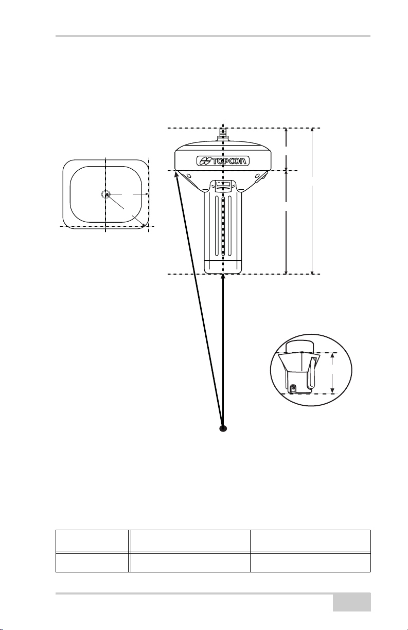
Receiver Setup
1. Measure the antenna height above the control point or marker,
either the slant height or the vertical height (Figure 4-3).
2. Record the antenna height, point name, and start time in the field
notes.
66.5mm
228mm228mm228mm228mm228mm228mm234.5mm
A
B
A = ARP to edge = 78.3
B = ARP to corner = 96.7
168mm
Slant Height
to Base of
Corner on
Gray Bumper
Station Marker
or
Tip of RTK Pole
Figure 4-3. Antenna Offset Measurements
Vertical Height
to ARP
When measuring the height of
the Rover antenna, include the
height of the Quick Disconnect.
• SHMM to ARP vertical offset = 168mm
• SHMM to ARP radius = 78.3mm to side; 95.8mm to corner
Table 4-1 gives the offset values for the receivers.
Table 4-1. Offset Values for GR-3 Receiver
ARP To L1 Phase Center ARP To L2 Phase Center
Up 228.8mm 216.3mm
49mm
P/N 7010-0736
4-5
Page 98

GR-3 Receiver Setup and Survey
Step 3: Collect Data
See the remaining sections in this chapter for more information on
collecting data.
1. Turn on the receiver. The STAT (status) light (LED) will blink red
at first.
2. Once the receiver has locked on to one or more satellites, the
STAT light will blink green for GPS satellites and orange for
GLONASS satellites. A short red blink indicates that the receiver
has not solved a position. Four or more satellites provide optimal
positioning.
3. Once the short red blink is gone, the receiver has a position and
surveying can begin; wait for green and orange lights before
beginning data collection. This ensures that the receiver has the
correct date and time, and is locked on to enough satellites to
ensure good quality data.
The process of locking on to satellites normally takes less than
one minute. In a new area, under heavy tree canopy, or after
resetting the receiver, it may take several minutes.
4. To begin collecting data, press and hold the FUNCTION key (for
more than one second and less than five seconds).
5. Release the FUNCTION key when the REC (recording) LED
turns green. This indicates that a file has opened and data
collection has started. The REC LED blinks each time data is
saved to the internal memory.
Use PC-CDU to configure data logging. See
TIP
“MINTER Configuration” on page 3-20 or refer to
the PC-CDU Reference Manual.
6. When finished, press and hold the FUNCTION key until the
REC LED light goes out.
7. To turn off the receiver, press and hold the power key until all
lights go out, then release.
4-6
GR-3 Operator’s Manual
Page 99
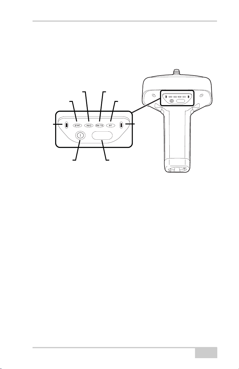
MINTER Operation
MINTER Operation
The MINTER is the receiver’s minimum interface used to display and
control data input and output (Figure 4-4).
REC RX TX
STAT
BT
FUNCTION
Battery
Power
Button
FUNCTION
FUNCTION
Button
Figure 4-4. GR-3 MINTER
Battery
The MINTER performs numerous functions, including the following:
• Turns the receiver on or off.
• Turns data recording on or off (FUNCTION key).
• Changes the receiver’s information mode.
• Shows the number of GPS (green) and GLONASS (orange)
satellites being tracked (STAT LED).
• Shows the data recording status and each time data is recorded to
internal memory (REC LED).
• Shows the status of post-processing mode (static or dynamic)
during a post-processed kinematic survey (REC LED).
• Shows the status (high charge, intermediate charge, or low
charge) of the battery (BATT LED).
• Shows the power status for the receiver (BATT LED).
• Shows the status of the modem and if it receives signals (RX TX
LED).
• Show Bluetooth activity (BT LED).
P/N 7010-0736
4-7
Page 100
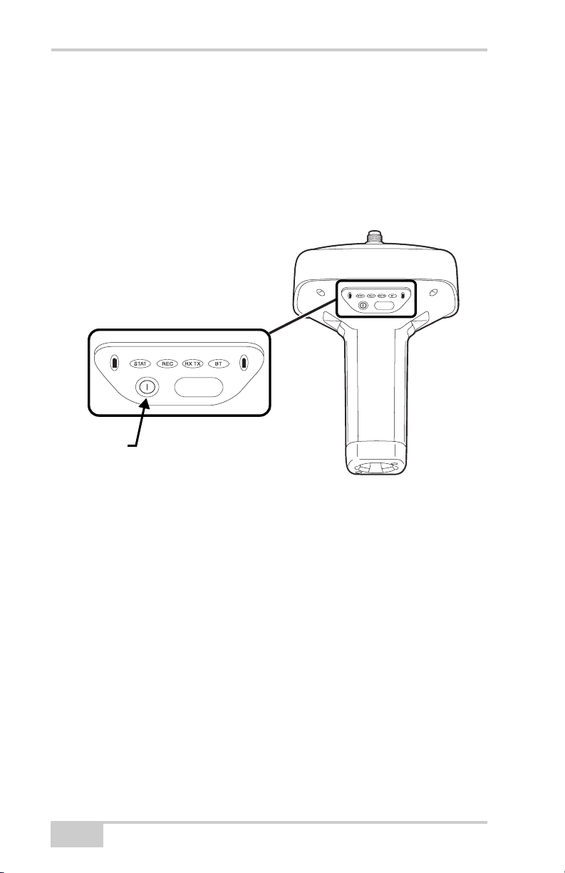
GR-3 Receiver Setup and Survey
See “MINTER” on page 1-11 for a full description of the MINTER.
To turn on/off the receiver, press the power button (Figure 4-5).
• When turning on, press the power button until the MINTER’s
LEDs briefly flash.
• When turning off, press the power button until the LEDs go out,
then release.
Press the power
button for about 1
second to turn the
receiver on/off.
FUNCTION
FUNCTION
Power
Button
Figure 4-5. Power Button Functions
To start/stop logging data, press the FUNCTION button for 1–5
seconds (Figure 4-6).
• During data recording, the REC LED is green. Use PC-CDU to
set the recording time interval. See “Recording Interval
parameter” on page 3-22 for details.
• The REC LED blinks green each time data is written to the SD/
MMC memory.
• If the REC LED is red, the receiver has run out of memory, has a
hardware problem, has no SD/MMC card, or contains an
improper OAF (see “Option Authorization File (OAF)” on
page 1-23 for more information).
Use PC-CDU to enable the desired FUNCTION key mode in the
receiver, either “LED blink mode switch” for static surveys or
4-8
GR-3 Operator’s Manual
 Loading...