

Page 1

RH-1 USERS MANUAL
Please read these Terms and Conditions carefully.
This product is designed to be used by a professional. The user should have a good knowledge
of the safe of the product and implement the types of safety procedures recommended by the
local government protection agency for both private use and commercial job sites.
Any changes or modifications to the equipment not expressly approved by the
party responsible for compliance could void your authority to operate such
equipment.
Turn off the power supply near a highly accurate electronic equipment.
RH-1
・Outline of product
RH-1 is GPS receiver in GRS-1 to measure the GPS data in real time.
RH-1 supplies the electric power to GRS-1 by two battery and outside AC power, and
enables the operation of GRS-1 of long time.
・Surveying to use the wireless modem
This method of GPS survey allows the operator to reduce the point occupation time, thus permitting
field crews to survey many more points compared to the other methods available.
Real Time Kinematic Surveying
In RTK surveying, one receiver serves as the reference station. The receiver conducts observations
with its antenna affixed to a stationary tripod or another device. The second receiver functions as a
rover, and conducts observations (using an antenna) affixed to a mobile pole and moved to
observation points.
Unlike post-processed kinematic surveys, RTK surveys uses a communications link between the
Base and Rover. Using a radio modem link, the Base receiver transmits its measurement and location
data to the Rover receiver. The Rover, based on the transmitted data and its own observation data,
immediately conducts a baseline analysis and outputs the results.
The GPS receiver receives the correction data that RH-1 received through the connection by
Bluetooth.The GPS receiver uses GRS-1 usually.
General Specification
Table A-1 Physical Specification
Table A-2 lists the Bluetooth wireless technology module’s general
Table A-3 lists the internal Digital UHF Modem’s General Specifications For RH-1/U
Table A-4 lists the internal Spread Spectrum Modem’s General Specifications For RH-1 /FH
(1/10)
Page 2
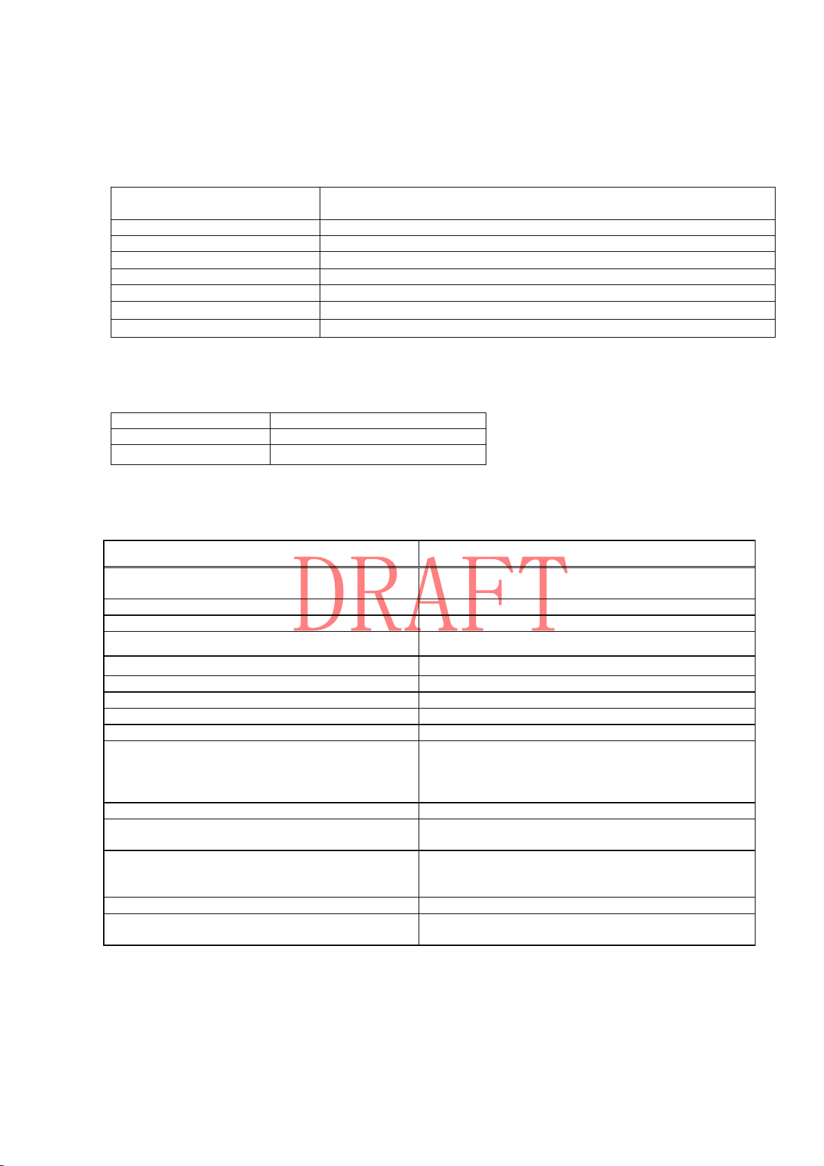
Physical Specifications
Table A-1 Physical Specification
Dimensions 8.50” x 5.83” x 6.71” ( 216 x 148 x 170.5 mm ) ※no Antenna
15.47” x 5.83” x 6.71” ( 393 x 148 x 170.5 mm ) ※with Antenna
Weight 1.4Kg
Input / output Bluetooth,Serial, Power, Antenna,Communication pins(for GRS-1)
Battery Type Li-ion battery, Rechargeable / Replaceable
Input voltage 12V
Operating temperature -20 C° to +50 C°
Strage temperatuere -30 C° to +60 C°
Waterproof IPX4
Wireless specifications
Table A-2 Bluetooth Module Specifications
Range up to 10 m (indoor)
Type Class 2
Supported profiles SPP
Digital UHF Modem General Specifications(For RH-1 /U)
Table A-3 lists the internal Digital UHF Modem’s General Specifications
Parameter Specification
Operating frequency range
country/region/purpose dependent
Modulation techniques GMSK,
Channel spacing 12.5 kHz/25 kHz
Transmission rates at 25 kHz spacing • GMSK– 9600 bps
Transmission rates at 12.5 kHz spacing • GMSK– 4800 bps
Data speed of serial interface Max 115200 bps
Forward Error Correction Available
Scrambling Available
Communication mode Half-Duplex
Output power 0.01 W (+10dBm), 0.02 W (+13 dBm),
Nominal output impedance 50 Ohms 2.0:1 VSWR
Output power control accuracy + 1dB (at normal test condition)
Adjacent channel selectivity
Nominal output impedance 50 Ohms 2.0:1 VSWR
Output power control accuracy
410-470 MHz
0.05 W (+17 dBm), 0.1 W (+20 dBm),
0.25W (+24 dBm), 0.5 W (+27 dBm),
1W (+30 dBm)
+2.0 dB and -3.0 dB (under extreme test condition)
-70 dB for 25 kHz Channel Spacing
-60 dB for 12.5 kHz Channel Spacing
+ 1dB (at normal test condition)
+2.0 dB and -3.0 dB (under extreme test condition)
(2/10)
Page 3

Spread Spectrum Modem’s General Specifications (For RH-1 /FH)
Table A-4 Internal Spread Spectrum Modem’s General Specifications
General
Frequency Range
country/region/
purpose dependent
Signal structuring Frequency-hopping spread spectrum
Hopping pattern 5 per band, user-selectable
Hopping channels 128
Occupied bandwidth 100 KHz
Frequency modulation
technique
System gain 135 dB
Network topology Point-to-point, Point-to-multipoint
Operation mode Transmitter, Receiver, Repeater
902 to 928 MHz, United States
915 to 925 MHz, Australia
FSK, 64 Kbps
Protocol FH915, FH915+
Transmitter (TX)
Carrier power 250 mW (24 dBm)/1 W (30 dBm), user selectable
Receiver (RX)
Sensitivity -105 dBm at 10-4 BER
Dynamic range 105 dBm
Data communications
Serial interface RS232
Serial data rate 9600, 19200, 38400, 57600 bps, user selectable
Effective radio link rate 9600, 10200, 17000, 51000 bps
User selectable for FH915; automatic selection for FH915+
Error correction FEC (15.7), majority decoding
Antenna Type
Type 1/2 wave articulating whip
Connector Reverse TNC polarity
GAIN 2.4dBi
(3/10)
Page 4
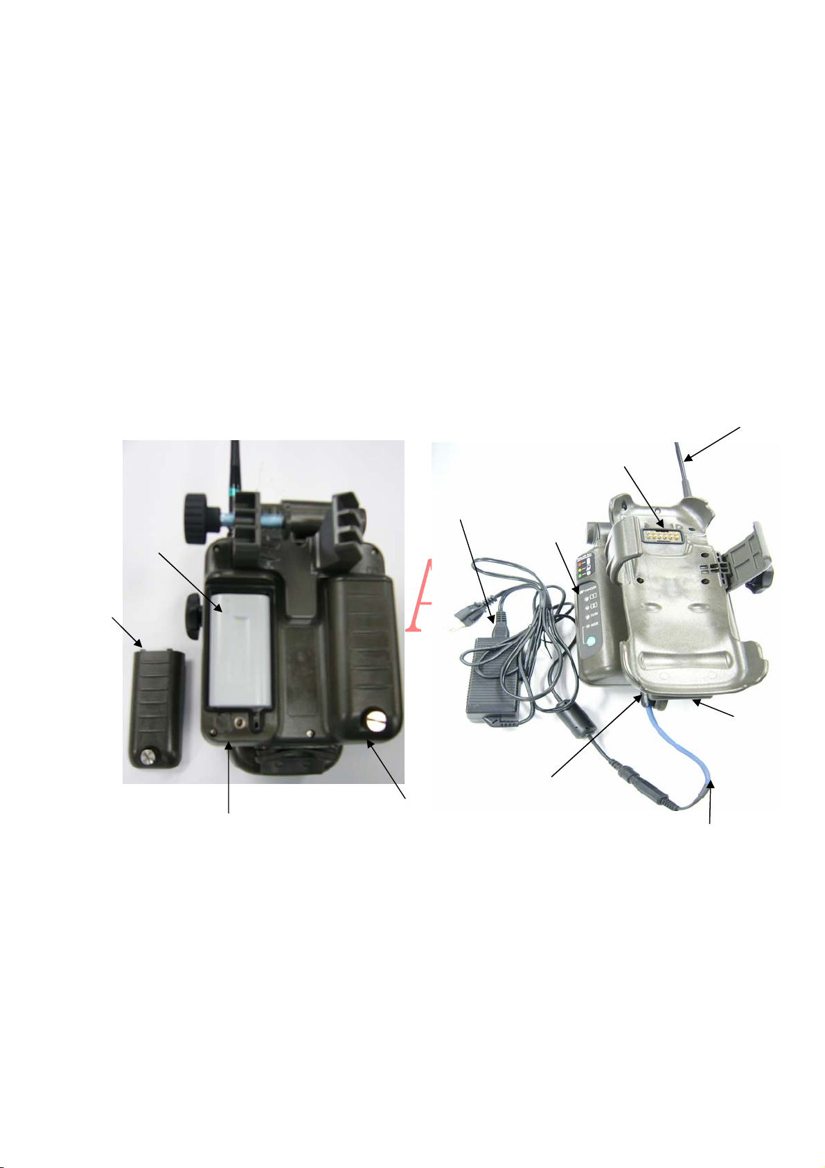
・RH-1 standard package includes
・Radio Holder unit
・Two Li-ion Battely
・Radio antenna
・Power adptor AD-11 (AC-DC Adptor)
・AC Cable ( for AD-11)
・Serial Cable ( DB9 )
External port
(COM Port2)
Modem Antenna
BT-66Q
Battery Cover
Battery1
Power adapter
Side Panel
External port
(COM Port1)
Power port
Battery2
Convert Cable
(4/10)
Page 5
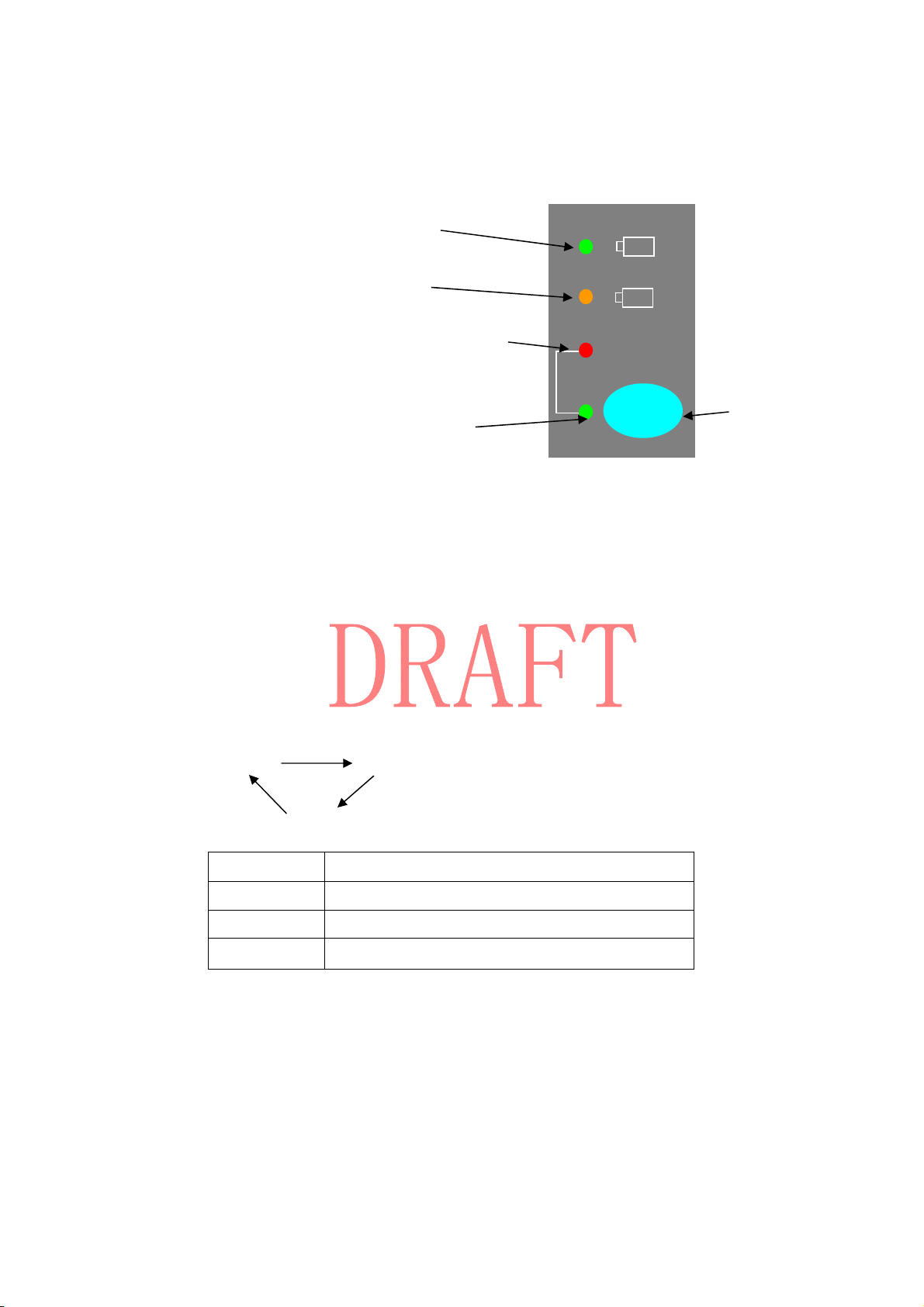
BATTERY1 LED
Side Panel
1
BATTERY2 LED
MODEM STATUS LED
2
TX/RX
MODE LED
MODE
POWER/MODE KEY
Power ON/OFF
ON :Pressing the MODE key turns the RH-1 on.
OFF:Pressing the MODE key for 5 seconds or more turns the RH-1 off.
MODE key Functions and connection mode LED status
Pressing the MODE key for 0.3 second, changing the MODE and change the color.
GREEN
Pressing
MODE key
Pressing
MODE key
Red
Pressing
MODE key
Orange
LED Function of the MODE
GREEN Connecting with GRS-1 using Bluetooth.
Orange Connecting MODEM with COM Port 1
RED*1 Connecting COM Port1 with ComPort2.
*1: It is necessary to connect RH-1 and GRS-1 by using Bluetooth to use this function.
TX/RX LED STATUS
Display the communication of the modem.
(The lighting pattern must depend on the internal modem).
(5/10)
Page 6
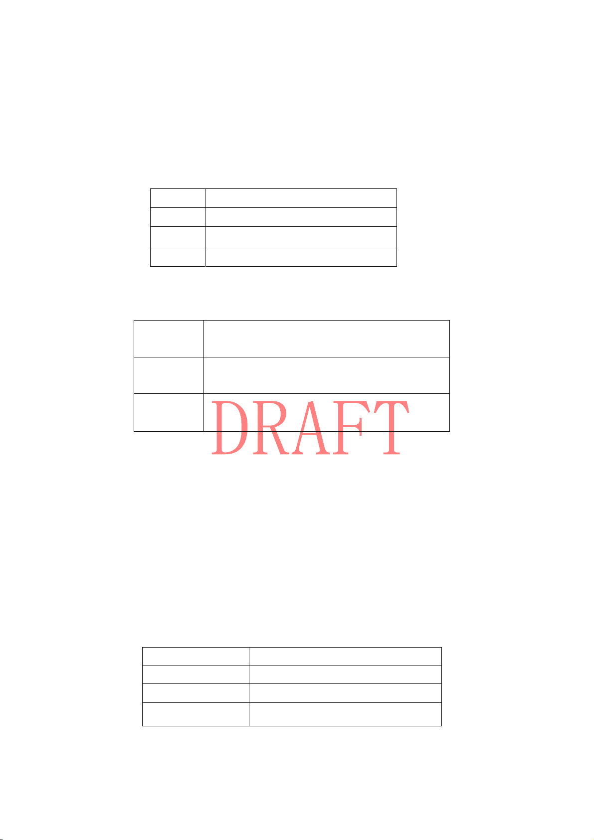
About BATTERY LED
The color of the battery LEDs display the status of th remaning charge for the
corresponding battery and is the same for LEDs:
Green More than 60%
Orange 20% to 60%
Red Less than 20%
No light There is not battery
The blink interval and length of time lit of the battery LEDs display the status
of the battery when in use:
In use:
Not in use
a 2second light in 0.5 second intervals
*Color is depended on the remaining charge
Solid light
*Color is depended on the remaining charge
Error Rapid red blink
(EX. Open the battery’s cover)
The charging with the AC adaptor
The AC Adaptor supports charging-on-the-run for RH-1
With the adapter plugged into an AC outlet and the batteries installed,the
batteries will also be charged.
The charging status varies depending on the state of the batteries.
Both battery LEDs use the same blink pattern while the corresponding battery
charge.
While charging,the battery LED for the charging battery blinks in 2 second
intervals.
Solid green light battery charging is completed
Red blink Charging battery
Solid Orange Not in charging
Rapid red blink Charging error
(6/10)
Page 7
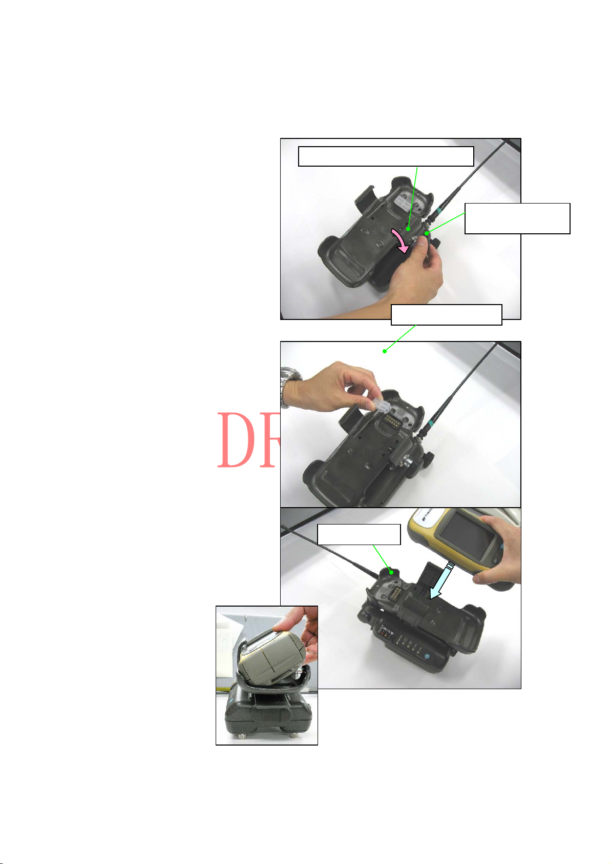
Joint method with GRS-1
Turn the knob, and open the arm
for GRS-1.
Remove the contact cover.
Arm for GRS-1 fixation
Knob for GRS-1 fixation
Contact cover
Insert GRS-1 from the left side
in the holder of RH-1.
Holder
(7/10)
Page 8
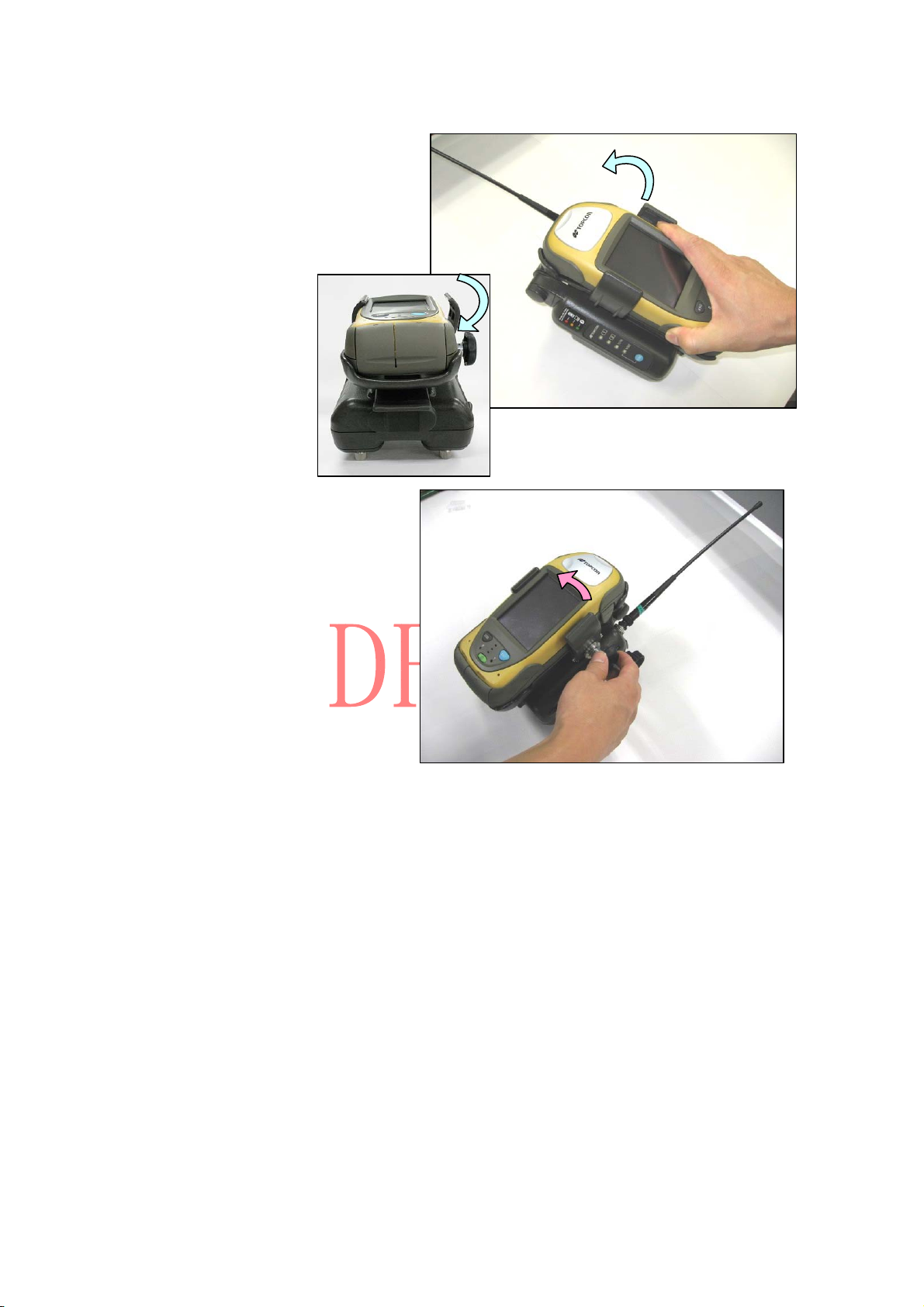
Set GRS-1 up in the holder.
Turn the knob, and fix GRS-1.
Notes
The power supply of RH-1 does not turn on if the knob does not surely close.
When GRS-1 is repeatedly detached, externals of GRS-1 are damaged.
The shape of the holder will be changed as measures of the above-mentioned trouble point.
(8/10)
Page 9

FCC Regulatory Statement
This device complies with Part 15 of the FCC Rules. Operation is subject to the following two
conditions: (1) This device may not cause harmful interference, and (2) This device must
accept any interference received, including interference that may cause undesired operation.
Caution:
Any changes or modifications not expressly approved by the party responsible for product
compliance could void the user's authority to operate the equipment.
Caution Exposure to radio frequency radiation
To comply with FCC RF exposure compliance re quirements, a separation distance of at least 20
cm must be maintained between the antenna of this device and all persons. This device must not
be co-located or operating in conjunction with any other antenna or transmitter.
(9/10)
Page 10

Industry Canada
Canada Regulatory Compliance Statement
This Class B digital apparatus complies with Canadian ICES-003.
Cet appareil numériqué de la classe B est conformé à la norme NMB-003 du Canada.
For Customers in Canada
This device complies with RSS 210 of Industry Canada (IC).
Operation is subject to the following two conditions:
・this device may not cause interference, and
・this device must accept any interference, including interference that may cause undesired
operation of this device.
L’utilisation de ce dispositif est autorisée seulement aux conditions suivantes:
・il ne doit pas produire de brouillage et
・I'utilisateur du dispositif doit étre prêt a accepter tout brouillage radioélectrique reçu,
même si ce brouillage est susceptible de compromettre le fonctionnement du dispositif.
Exposure to radio frequency radiation
The installer of this radio equipment must ensure that the antenna is located or pointed such
that it does not emit RF field in excess of Health Canada limits for the general population;
consult Safety Code 6, obtainable from Health Canada’s website at www.hc-sc.gc.ca/rpb.
(10/10)
 Loading...