


Chapter 4
Operation
This chapter describes standard receiver operating procedures:
•Using the MINTER
• Downloading receiver files to a computer
• Deleting files from the receiver
• Checking and loading OAFs
• Managing receiver memory
• Clearing the NVRAM
• Changing receiver modes
• Checking and loading firmware
Topcon receivers are built to operate independent of the receiver type.
Any minor exceptions for the HiPer XT are noted.
P/N 7010-0713
4-1
Operation
Using the MINTER
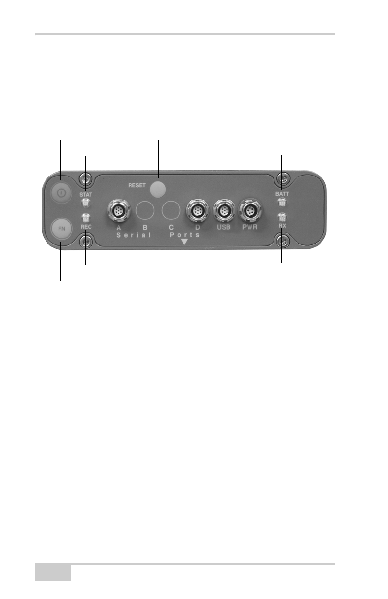
The MINTER (Figure 4-1) is Topcon’s Minimum INTERface used to
display and control data input and output, and is the same for all
HiPer family receivers.
Power Button
STAT (status LED)
REC (recording LED)
FN (function/recording button)
Reset
Figure 4-1. MINTER
BATT
(battery LED)
RX
(modem status LED)
Power Key
Pressing the power key turns the receiver on and off.
Status LED
• When the receiver is on and no satellites are tracked, the STAT
LED will blink red.
• When satellites are tracked, the STAT LED will produce one
blink for each tracked satellite (green for GPS, orange for
GLONASS).
4-2
HiPer XT Operator’s Manual

Using the MINTER
Reset Key
Pressing and holding the reset key for about one second causes:
• a hard reset of the receiver.
• the receiver to leave Zero Power Mode and return to Normal
Mode.
NOTICE
NOTICE
Only use this procedure if the receiver does not respond to
commands or does not charge the internal batteries (is in
Zero Power Mode).
FN Key and Record LED
Table 4-1 on page 4-5 summarizes FN key functions and REC LED
statuses. See “FN Key Mode parameter” on page 2-23 for information
on setting FN key modes.
• Pressing the FN key for less than one second switches the
receiver between different information modes (normal and
extended information), or between static and dynamic postprocessing modes, depending on the receiver's configuration.
During the first second of pressing the FN key, the REC LED is
orange.
• Pressing and holding the FN key for more than one and less than
five seconds will start/stop data recording.
During data recording the REC LED is green.
If the REC LED is red, the receiver has run out of memory, has a
hardware problem, or contains an improper OAF (see “Option
Authorization File (OAF)” on page 1-16 for more information on
OAFs).
• The REC LED blinks green each time data is written to the
internal receiver’s memory.
You set the data recording time interval using PC-CDU. See
“Recording Interval parameter” on page 2-20 for information on
setting this function.
P/N 7010-0713
4-3

Operation
Each time you turn off or on data recording, either a new file
opens or data appends to a particular file. See “Always Append to
the File parameter” on page 2-21 and “Files Creation Mode
parameter” on page 2-21 for information on setting this function.
• Pressing and holding the FN key for more than five and less than
eight seconds will turn the baud rate of serial port A to 9600.
After about five seconds of pressing the FN key, the REC LED
becomes red. Release the FN key while the REC LED is red
(during the next three seconds).
Pressing and holding the FN key for more than eight seconds has
no impact.
• After loading new firmware or clearing the receiver’s NVRAM,
the receiver checks its internal file system.
During this operation, the REC LED flashes orange, and the file
system is not accessible for CDU (control display unit)
applications or for data recording. This operation may require
from fractions of a second to several minutes, depending on the
circumstances and the amount of internal memory.
4-4
HiPer XT Operator’s Manual
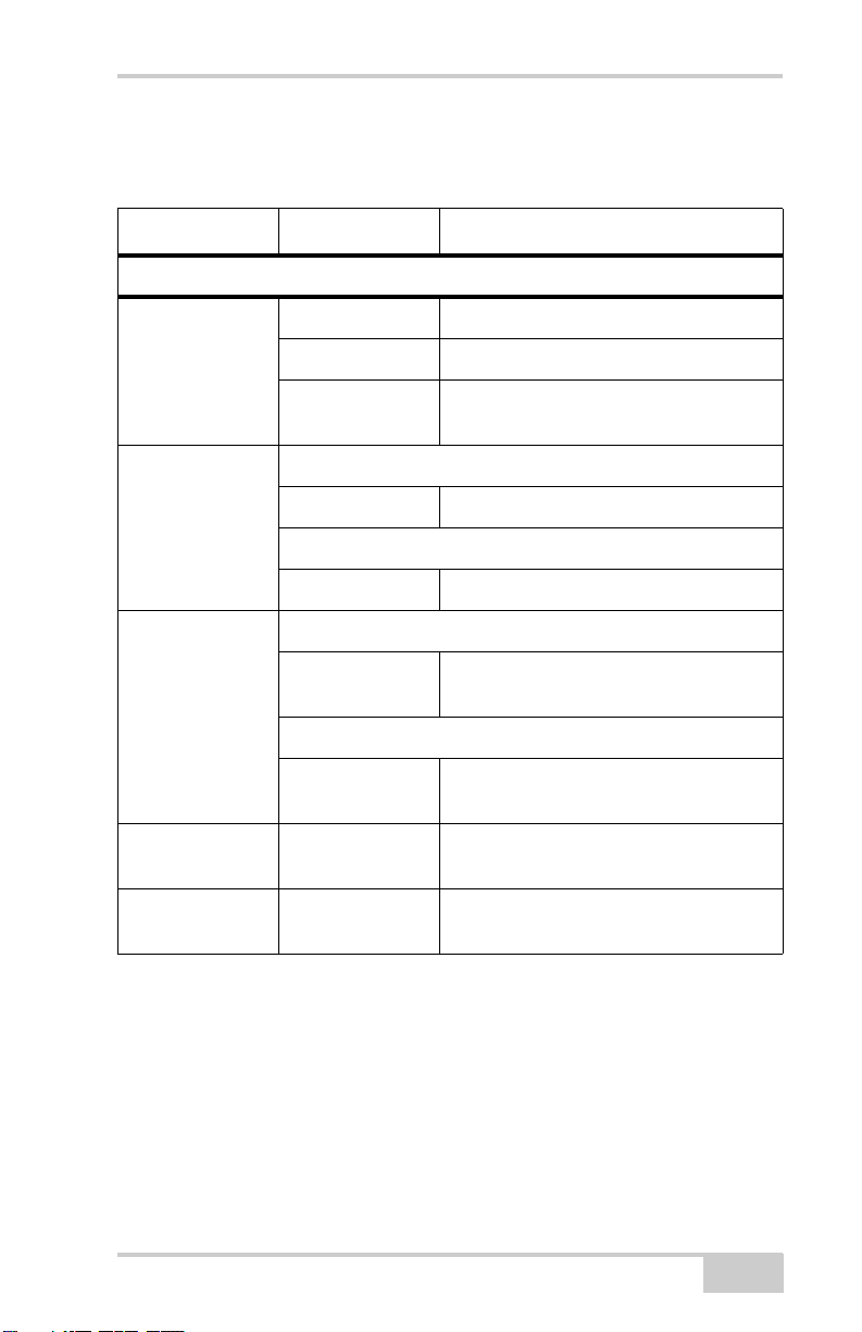
Table 4-1. FN Key Functions and REC LED Status
FN Key REC LED Status
When data recording is off, and the FN key is...
No light No data recording.
Using the MINTER
Not pressed
Pressed for < 1
second
Pressed for 1–5
seconds
Pressed for 5–8
seconds
Pressed for > 8
seconds
Orange blink Internal file system test in progress.
Red No free memory; hardware problem
with data recording.
If FN key mode is “LED blink mode switch”
Orange Release to change information mode.
If FN key mode is “Occupation mode switch”
Orange No function.
If FN key mode is “LED blink mode switch”
Green Release to start data recording (post-
processing occupation mode undefined).
If FN key mode is “Occupation mode switch”
Green Release to start recording (Kinematic or
Static post-processing occupation mode)
Red Release to turn serial port A baud rate to
9600 bps.
No light No function.
P/N 7010-0713
4-5
Operation
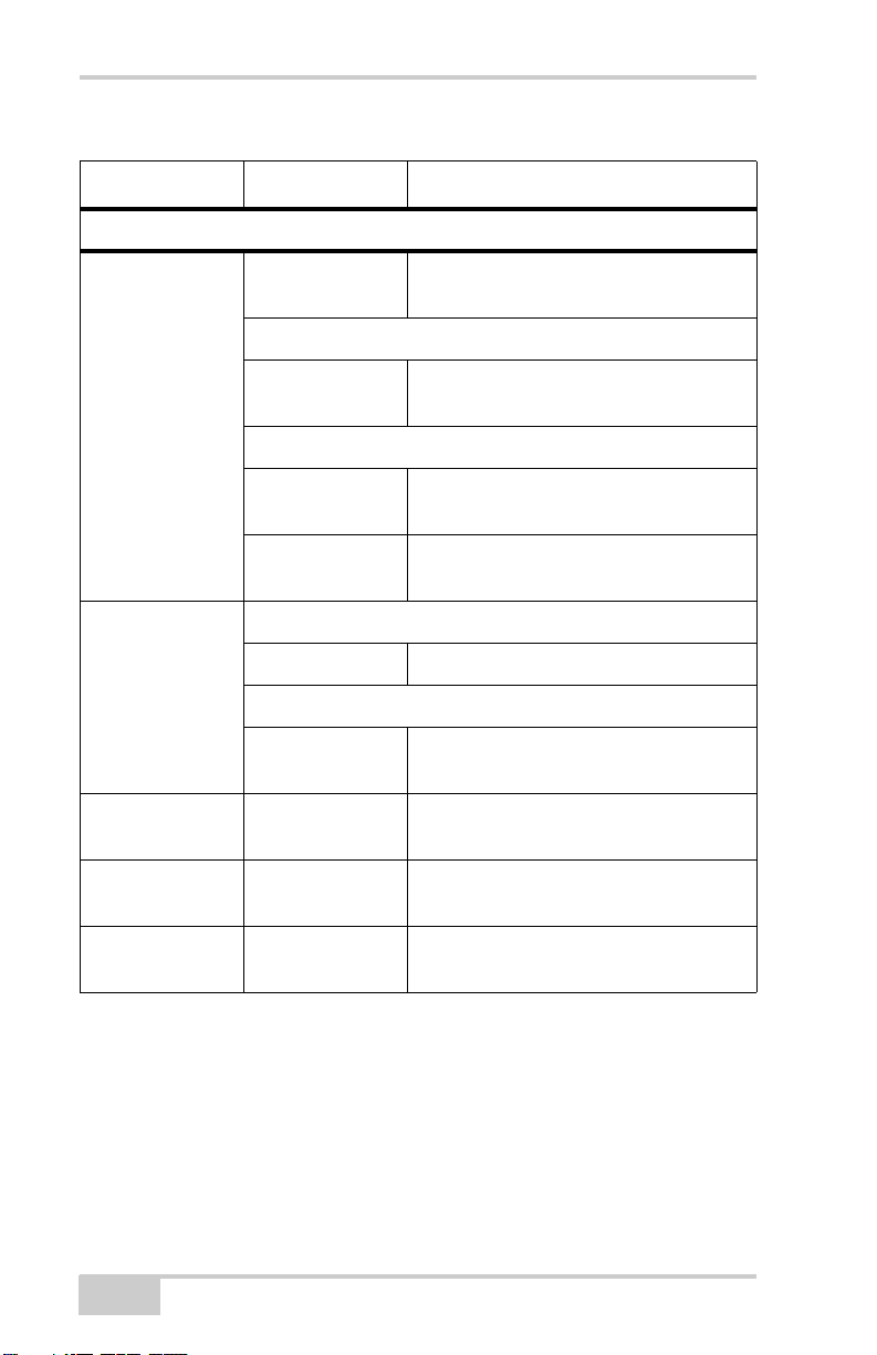
Table 4-1. FN Key Functions and REC LED Status (Continued)
FN Key REC LED Status
When data recording is on, and the FN key is...
Red No free memory; hardware problem
with data recording.
If FN key mode is “LED blink mode switch”
Green Data recording started (post-processing
Not pressed
occupation mode undefined).
If FN key mode is Occupation mode switch
Green Data recording started (Kinematic post-
processing occupation mode).
Orange Data recording started (Static post-
processing occupation mode).
If FN key mode is “LED blink mode switch”
Pressed for < 1
second
Pressed for 1–5
seconds
Pressed for 5–8
seconds
Pressed for > 8
seconds
4-6
Orange Release to change information mode.
If FN key mode is “Occupation mode switch”
Orange Release to toggle between Static and
Kinematic post-processing modes.
No light Release to stop data recording.
Red Release to turn serial port A baud rate to
9600 bps.
No light No function (data recording still on).
HiPer XT Operator’s Manual

Using the MINTER
Battery LED
The color of the BATT LED indicates the level of internal battery
charge in the HiPer XT:
• Green – indicates greater than 85% charge.
• Orange – indicates an intermediate charge.
• Red – indicates less than 15% charge.
The pattern of blinks of the BATT LED also indicates the source of
power.
• Solid light – an external power supply is used and the batteries are
not being charged.
• Blinking once a second – the batteries are being charged.
• Blinking once every five seconds – the HiPer XT uses the internal
batteries for power.
• Not blinking – the receiver is in Zero Power Mode or the internal
batteries are completely discharged and no external power is
connected.
NOTICE
NOTICE
When the internal batteries have completely discharged
and no external power is connected, the receiver will go
into Zero Power Mode to prevent the batteries from over
discharging.
P/N 7010-0713
4-7

Operation
Modem LED
The color of the TX/RX modem LED indicates if the modem has
power, is receiving signals, or is turned off.
For the UHF modem:
• No light – modem is turned off
• Solid Red – the modem is in transmitter mode; the modem is
transmitting data.
• Red flashes plus Green flashes – the modem is in command
mode. This mode allows the operator to send/query commands to/
from the modem.
• Solid Green – the modem is in receiver mode.
• Solid Orange (Red and Green) – the modem is receiving data.
• Red flashes – a fault condition has been detected. Check the
condition of the radio modem’s antenna to ensure it is
undamaged, and is connected properly and securely. Also make
sure that there are no conduction objects near the antenna
location.
For the GSM modem:
• Solid Orange (Red and Green) – the modem is initializing.
• Green flashes – the modem is on, registered on the network, and
is waiting for incoming calls (Slave mode).
• Solid Red – a connection has been established.
• Green flashes – the modem is in direct control mode (Daisy
Chain).
• Orange flashes – an error has occurred (initialization error, wrong
PIN code, etc.).
4-8
HiPer XT Operator’s Manual

Using the MINTER
Information Modes
The receiver has two information modes: Normal and Extended
Information Mode (EIM).
Normal
In normal mode, the STAT LED indicates the number of tracked
satellites and the position’s computation status.
Extended Information Mode (EIM)
Extended Information Mode (EIM) is used for receiver testing
purposes. In this mode, the receiver continues to work as usual, but
the STAT LED indicates “extended” information using a delimiter.
The Delimiter is a distinguishable double-blink that shows the overall
status of tests performed in EIM. The LED color for delimiter is
calculated from the colors of other LED blinks, and will be one of the
following colors when the tests complete:
• Orange – at least one blink is orange.
• Red – no orange blink and at least one red blink.
• Green – all other cases.
The delimiter double-blink is followed by six LED blinks
corresponding to six receiver tests, where each blink indicates the
following information:
Blink 1. Sufficient data for position computation.
Blink 2. GPS S/N ratios are good (Table 4-2 on page 4-10).
Blink 3. GLONASS S/N ratios are good (Table 4-2 on page 4-
10).
Blink 4. Oscillator’s frequency offset is less than three ppm.
Blink 5. Oscillator's Allan Variance is better than 2.7e-10.
Blink 6. Continuous tracking time is more than 15 minutes.
P/N 7010-0713
4-9

Operation
Table 4-2. Signal-to-Noise (S/N) “Good” Ratios
CA/L1 P/L1 P/L2
GPS513939
GLONASS 51 49 40
The color of the blink indicates that information for test is unavailable
(orange), the receiver passed the test (green), or the receiver failed the
test (red).
1. To switch to EIM, press and quickly release (within one second)
the FN key on the MINTER.
2. Watch for the delimiter double-blink. With good receiver,
antenna, and observation conditions, all blinks should be green
within 15 minutes of powering on.
• Green – ok
• Orange – wait
• Red – some tests failed
3. To switch back to normal mode, press the FN key.
Downloading Files to a
Computer
When your survey finishes, you can download survey files to a
computer for storage, post-processing, or backup. Also, the receiver
memory holds a finite amount of files and information, so
downloading the files prevents files from being lost.
You should download files as soon as possible after collecting data at
the jobsite. PC-CDU provides a File Manager to download files to
your computer and delete files from the receiver.
1. Connect your receiver and computer. See “Connecting the
Receiver and a Computer” on page 2-10 for this procedure.
4-10
HiPer XT Operator’s Manual
Downloading Files to a Computer
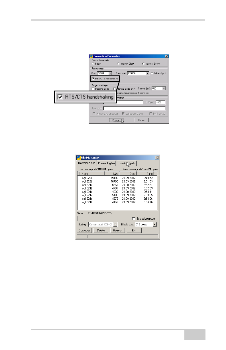
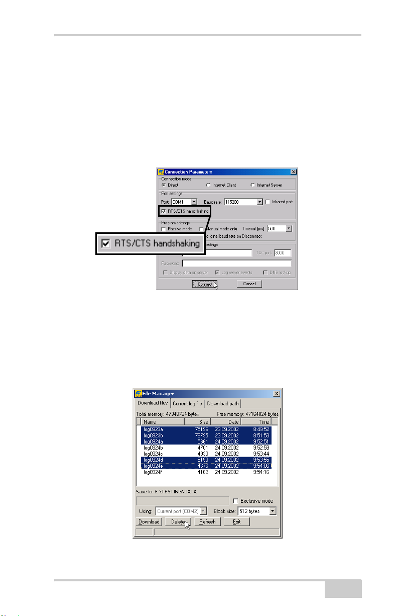
2. On the Connection Parameters dialog box, enable RTS/CTS
handshaking and click Connect (Figure 4-2).
Figure 4-2. Connection Parameters – RTS/CTS Handshaking
3. Click FileFile Manager, then click the Download path tab on
the File Manager dialog box (Figure 4-3).
Figure 4-3. Find Files to Download
4. Navigate to or create (using the Create button) the folder in
which to download and store files.
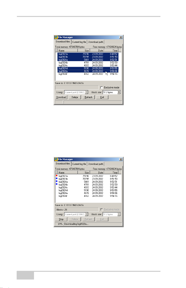
5. Click the Download files tab and select the file(s) to download
(Figure 4-4 on page 4-12).
To select multiple files, hold down the shift key and click on nonsequential files to select several files at once; or, hold down the
Ctrl key and click on individual files.
P/N 7010-0713
4-11
Operation
Figure 4-4. Download Files
6. Click the Download button. During the download, status
indicators display next to each file (Figure 4-5).
• Blue indicator – file in queue for downloading.
• Red indicator – file currently downloading.
• Green indicator – file has successfully downloaded.
Figure 4-5. Download Files – Status Indicators
7. Click Exit on the File Manager dialog box.
8. Continue with other operations. Or, click FileDisconnect, then
FileExit to quit PC-CDU.
4-12
HiPer XT Operator’s Manual
Deleting Files
Deleting Files
Use the following steps to delete files from your receiver.
1. Connect your receiver and computer. See “Connecting the
Receiver and a Computer” on page 2-10 for this procedure.
2. On the Connection Parameters dialog box, enable RTS/CTS
handshaking (Figure 4-6).
Figure 4-6. Connection Parameters – RTS/CTS Handshaking
3. Click FileFile Manager and select the file(s) to delete on the
Download files tab (Figure 4-7).
To select multiple files, hold down the shift key and click on nonsequential files to select several files at once; or hold down the
Ctrl key and click on individual files.
P/N 7010-0713
Figure 4-7. Delete Files
4-13
Operation
4. Click Delete (Figure 4-7 on page 4-13).
5. Click Ye s at the delete files confirmation dialog box. PC-CDU
deletes the selected files.
6. Click Exit on the File Manager screen.
7. Continue with other operations. Or Click FileDisconnect, then
FileExit to quit PC-CDU.
Checking Receiver Options
TIP
TIP
For a complete list of options and their details, visit the
Topcon website.
You can check the status of your receiver’s options, and load any new
OAFs, using the RS232 cable, a computer, and PC-CDU. Refer to the
PC-CDU User’s Manual for a more complete description of the
PC-CDU software.
1. Connect your receiver and computer. See “Connecting the
Receiver and a Computer” on page 2-10 for this procedure.
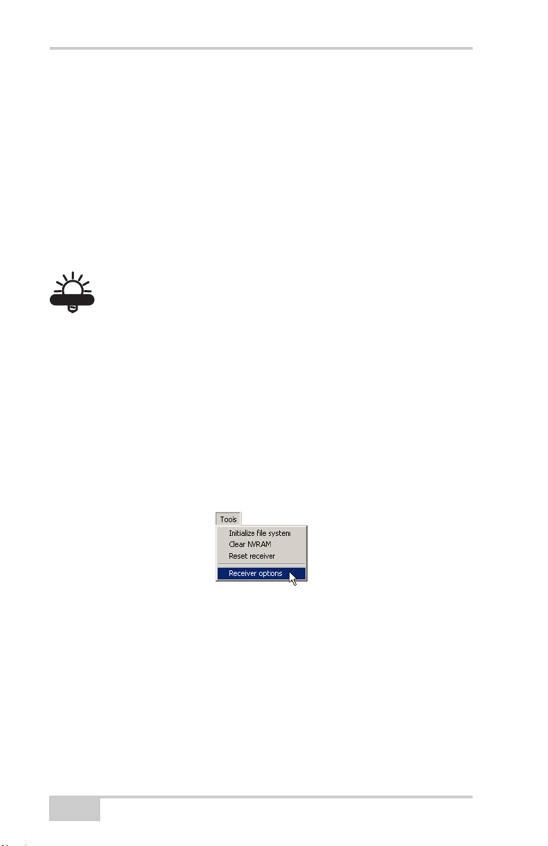
2. Click Too ls Receiver Options (Figure 4-8).
Figure 4-8. Open Receiver Options
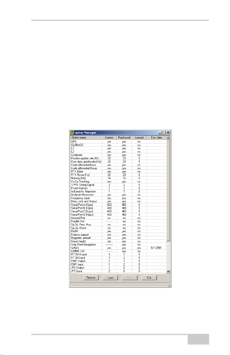
The Options Manager dialog box (Figure 4-9 on page 4-15)
contains the following information:
• Option name – a name/description of the option
• Current – the current status of the option
• Purchased – if the option is purchased or not
• Leased – if the option is leased or not
4-14
HiPer XT Operator’s Manual
Checking Receiver Options
• Expiration date – the date the option will be disabled, if
applicable
Since Options can be both purchased and leased, the “Current”
status of the option displays the currently effective value. Option
values can be:
• -1 or “-----” – the firmware version does not support this
option.
• 0 – the receiver option is disabled.
• positive integer – the option is enabled.
• yes or no – the option is either enabled or disabled.
Figure 4-9. Option Manager
3. When finished, click Exit on the Option Manager screen, then
click FileDisconnect to prevent conflicts with serial port
management.
P/N 7010-0713
4-15
Operation
Loading OAFs
Topcon Positioning System dealers provide customers with OAF
files. For any OAF related questions, E-mail TPS at
options@topconps.com. Please have your receiver ID number
available (see “Checking Firmware Version” on page 4-20).
1. To load a new OAF, follow steps one and two in “Checking
Receiver Options” on page 4-14.
2. Click Load at the bottom of the Option Manager dialog box (see
Figure 4-9 on page 4-15).
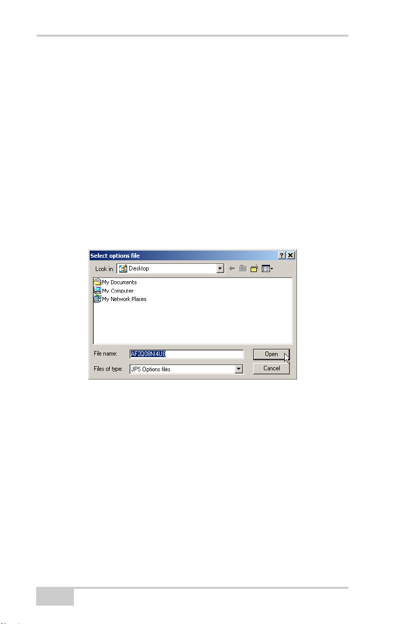
3. Navigate to the location of the new Option Authorization File.
OAFs have .jpo or .tpo extensions and are unique to each receiver
(Figure 4-10).
Figure 4-10. Load OAF
4. Select the appropriate file and click Open (Figure 4-10). The new
receiver option loads onto the receiver and the Option Manager
table updates.
5. When finished, click Exit on the Option Manager dialog box,
then click FileDisconnect to prevent conflicts with serial port
management.
4-16
HiPer XT Operator’s Manual

Managing Receiver Memory
Managing Receiver Memory
When using the receiver in static or dynamic applications, you may
need to know the amount of memory the receiver’s log file occupies.
The specific memory size depends on the type of data being recorded.
Use the formulas below to compute the approximate size of the
receiver’s log files. These equations are based on the default set of
messages.
• SS – the estimated size of one epoch of raw data in the receiver’s
log file (expressed in bytes).
• N – the number of observed satellites per epoch.
When recording only L1 data:
SS = 183 + 22*N
When recording L1 and L2 data:
SS = 230 + 44*N
Clearing the NVRAM
The receiver’s Non-Volatile Random Access Memory (NVRAM)
holds data required for satellite tracking, such as ephemeris data and
receiver position. The NVRAM also keeps the current receiver’s
settings, such as active antenna input, elevation masks and recording
interval, and information about the receiver’s internal file system.
Even though clearing the NVRAM is not a common (nor normally a
recommended) operation, there are times when clearing the NVRAM
can eliminate communication or tracking problems. Clearing the
NVRAM in your receiver can be interpreted as a “soft boot” in your
computer.
After clearing the NVRAM, your receiver will require some time to
collect new ephemerides and almanacs (around 15 minutes).
Clearing the NVRAM of your receiver will not delete any files
already recorded in your HiPer XT’s memory. However, it will reset
your receiver to factory default values.
P/N 7010-0713
4-17
Operation
In addition, the NVRAM keeps information about the receiver file
system. Note that after clearing the NVRAM, the receiver's STAT
LED will flash orange for a few seconds indicating that the receiver is
scanning and checking the file system.
Using MINTER to Clear NVRAM
1. Press the power key to turn off the receiver.
2. Press and hold the FN key.
3. Press and hold the power key for about one second. Release the
power key while continuing to hold the FN key.
4. Wait until the STAT and REC LEDs are green
5. Wait until the STAT and REC LEDs blink orange.
6. Release the FN key while the STAT and REC LEDs blink orange.
Using PC-CDU to Clear NVRAM
1. Connect your receiver and computer. See “Connecting the
Receiver and a Computer” on page 2-10 for this procedure.
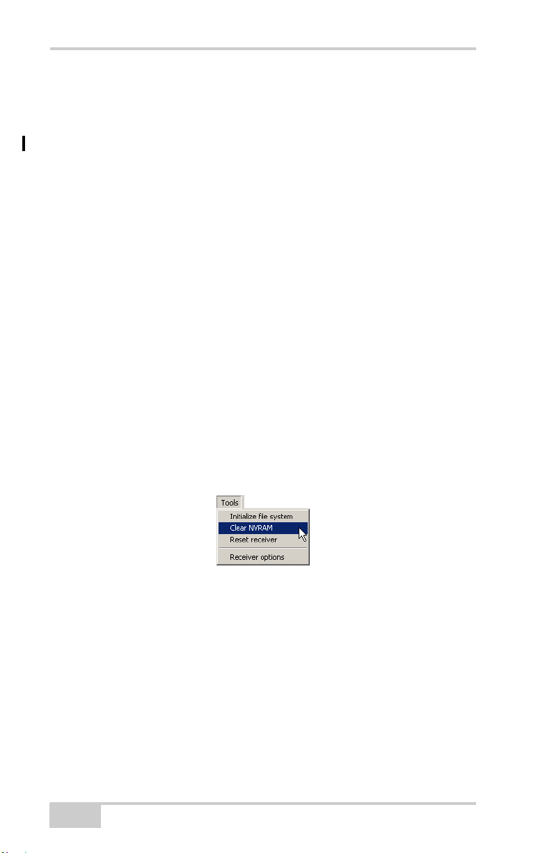
2. Click Too ls Clear NVRAM (Figure 4-11). The REC LED
flashes green and red; the STAT LED flashes red.
Figure 4-11. Clear NVRAM with PC-CDU
The receiver automatically disconnects when finished.
Changing Receiver Modes
The HiPer XT receiver has four modes, two information modes and
two power modes:
4-18
HiPer XT Operator’s Manual

Changing Receiver Modes
• Normal Mode
• Extended Information Mode
• Sleep Mode
•Zero Power Mode
See “Information Modes” on page 4-9 for a description of Normal
Mode and Extended Information Mode.
Sleep Mode
In sleep mode, the power board and Bluetooth module will continue
to draw power from the batteries, causing the batteries to drain over
time. Put the receiver in Zero Power Mode to prevent this (see “Zero
Power Mode” on page 4-19). Follow these steps to put the HiPer XT
into sleep mode.
1. Turn on your receiver.
2. Press and hold the receiver’s power key for more than four
seconds and less than eight seconds.
3. Release the power key when both the REC and STAT LEDs
become orange. The receiver enters Sleep Mode.
4. Any activity on the RS232 port will turn the receiver on.
NOTICE
NOTICE
If you press and hold the power key for more than 14
seconds, it will be ignored. This protects receiver operation
against stuck keys.
Zero Power Mode
When your receiver is off, even in Sleep Mode, the power board will
continue to draw power from the batteries. This means that if you
fully charge your receiver, turn it off and store it, the receiver will
drain its battery power in less than two months. To stop the power
P/N 7010-0713
4-19

Operation
board from draining the batteries, you can put your receiver in Zero
Power Mode.
1. Turn on your receiver.
2. Press and hold the power key for more than 8 seconds, but less
than 14 seconds.
3. Release the power key when both LEDs become red. When the
LEDs turn off, your receiver will be in Zero Power Mode.
4. Press the Reset key for about one second to return to Normal
mode.
NOTICE
NOTICE
When the internal batteries have completely discharged
and no external power is connected, the receiver will go
into Zero Power Mode automatically to prevent the
batteries from over discharging.
Checking Firmware Version
Use PC-CDU to check the firmware version of the receiver.
1. Connect the receiver and a computer. See “Connecting the
Receiver and a Computer” on page 2-10 for this procedure.
2. Click HelpAbout.
4-20
HiPer XT Operator’s Manual
Loading New Firmware
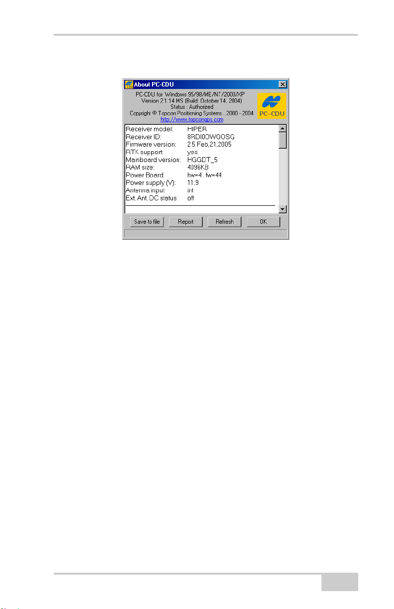
The About PC-CDU dialog box opens (Figure 4-12).
Figure 4-12. About PC-CDU
The About PC-CDU dialog box lists important information about
the different hardware accessories and software properties. This
list includes the following, which you will need if you contact
TPS or your dealer:
• Receiver model
• Receiver ID
• Firmware version
3. When finished, click OK, then click FileDisconnect to prevent
conflicts with serial port management.
Loading New Firmware
Base and Rover receivers must be loaded with the same firmware
version. Use the latest firmware version, available for download from
the TPS website, to ensure your receiver has the most recent updates.
P/N 7010-0713
4-21

Operation
NOTICE
NOTICE
The HiPer XT receiver should be loaded with firmware
version 2.5 or newer.
CAUTION
CAUTION
Do not use firmware versions 2.4 or older.
The receiver board and power board must be loaded with firmware
from the same package. The Bluetooth module’s firmware is
independent of the receiver card and power board, and has a different
firmware package.
The receiver uses FLoader, a Windows®-based utility, to load
firmware onto the receiver and power boards. You can download
FLoader to your computer from the TPS website. For more
information, refer to the FLoader User’s Manual, also available on
the TPS website.
1. Download and install FLoader, if applicable.
2. Download the new firmware package to your computer.
3. Connect your receiver and computer. See “Connecting the
Receiver and a Computer” on page 2-10 for this procedure.
4. Activate FLoader.
5. On the Connection tab, select the COM port on your computer
that connects with your receiver and select its speed (usually
115200) (Figure 4-13 on page 4-23).
4-22
HiPer XT Operator’s Manual
 Loading...