

Topcon America 841201 User Manual

POSITIONING SYSTEMS
GMS-2
Operator’s Manual
Part Number 7010-0752 DRAFT
Rev 2
©Copyright Topcon Positioning Systems, Inc.
April, 2006
All contents in this manual are copyrighted by Topcon. All rights reserved.
The information contained herein may not be used, accessed, copied, stored,
displayed, sold, modified, published, or distributed, or otherwise reproduced
without express written consent from Topcon.
Topcon only sells GPS products into Precision Markets.
Please go to www.topcongps.com for detailed market information.

ECO#xxxx

TOC
Table of Contents
Preface .................................................................. v
Terms and Conditions ...................................................... v
Manual Conventions ........................................................ viii
Chapter 1
Introduction .......................................................... 1-1
Principles of Operation .................................................... 1-2
GNSS Overview ........................................................ 1-2
Calculating Absolute Positions ........................... 1-3
Calculating Differential Positions ...................... 1-4
Essential Components for Quality Surveying .... 1-5
Conclusion .......................................................... 1-5
GMS-2 Overview ...................................................... 1-6
Getting Acquainted with the GMS-2 ............................... 1-7
Rechargeable and Backup Batteries .......................... 1-8
GMS-2 Front ............................................................. 1-8
GMS-2 Back .............................................................. 1-10
GMS-2 Ports .............................................................. 1-10
SD Card Slot ............................................................. 1-11
Integrated Camera ..................................................... 1-11
External GPS Antenna Connector ............................. 1-12
System Cables .................................................................. 1-12
GMS-2 Software .............................................................. 1-13
Optional Accessories ....................................................... 1-13
Option Authorization File (OAF) .................................... 1-15
Chapter 2
Preparing the GMS-2 for Use .............................. 2-1
Attaching the Hand Strap ................................................. 2-1
Powering the GMS-2 ....................................................... 2-2
Charging the Battery ................................................. 2-2
Charging and Battery Storage Notes ......................... 2-3
P/N 7010-0752
i

Table of Contents
Installing the Battery .................................................. 2-4
Replacing the Backup Battery ................................... 2-4
Starting the GMS-2 .......................................................... 2-6
Installing Software ........................................................... 2-7
Installing an Optional SD Card ........................................ 2-8
Chapter 3
Using the GMS-2 .................................................. 3-1
Connecting the GMS-2 with Other Devices .................... 3-1
Connecting the GMS-2 and a Computer ................... 3-2
Connecting the GMS-2 and a Bluetooth Device ....... 3-3
Surveying with the GMS-2 .............................................. 3-6
Surveying with the GMS-2 ........................................ 3-6
Surveying with the GMS-2 and an External Antenna 3-7
Surveying with the GMS-2 and a Beacon Receiver .. 3-8
Surveying with the GMS-2 and an
External GPS Receiver ........................................... 3-9
Backing up Windows CE RAM Data .............................. 3-10
Chapter 4
Troubleshooting .................................................. 4-1
Check This First! .............................................................. 4-1
Troubleshooting Quick List ............................................. 4-2
Resetting the Software ..................................................... 4-3
Restoring BTManager and Receiver Defaults ................. 4-3
Resetting the Hardware .................................................... 4-4
Charging/Powering Problems .......................................... 4-5
GMS-2 Problems .............................................................. 4-6
Bluetooth Problems .......................................................... 4-7
Obtaining Technical Support ........................................... 4-9
Phone ......................................................................... 4-9
E-mail ........................................................................ 4-9
Website ...................................................................... 4-10
ii
GMS-2 Operator’s Manual

Table of Contents
Appendix A
GMS-2 Software Reference ................................. A-1
BTManager ...................................................................... A-1
Getting Acquainted ................................................... A-1
Working with BTManager ........................................ A-4
Select Accessibility Options ............................... A-4
Enable Serial Port/Dial-up Services ................... A-5
Connect to a Bluetooth Device ........................... A-6
Resetting the Bluetooth Module ................................ A-8
GMS Tools ....................................................................... A-9
Getting Acquainted ................................................... A-9
Working with GMS Tools ......................................... A-11
Using the Camera ............................................... A-11
Using the Compass ............................................. A-12
Viewing GNSS Information and Logging Data . A-14
Appendix B
Specifications ....................................................... B-1
GMS-2 Specifications ...................................................... B-2
General Details .......................................................... B-2
GPS Details ............................................................... B-5
Connector Specifications ................................................. B-6
Serial Connector ........................................................ B-6
USB Connector ......................................................... B-7
Appendix C
Safety Warnings ................................................... C-1
General Warnings ........................................................... C-1
Battery Pack Warnings .................................................. C-1
Usage Warnings .............................................................. C-2
Appendix D
Regulatory Information ........................................ D-1
FCC Compliance ............................................................. D-1
Community of Europe Compliance ................................. D-2
WEEE Directive .............................................................. D-2
P/N 7010-0752
iii

Table of Contents
Appendix E
Warranty Terms ................................................... E-1
Index
iv
GMS-2 Operator’s Manual
Preface
Preface
Thank you for purchasing this Topcon product. The materials
available in this Manual (the “Manual”) have been prepared by
Topcon Positioning Systems, Inc. (“TPS”) for owners of Topcon
products, and are designed to assist owners with the use of the
receiver and its use is subject to these terms and conditions (the
“Terms and Conditions”).
NOTICE
Please read these Terms and Conditions carefully.
Terms and Conditions
USE This product is designed to be used by a professional. The user
should have a good knowledge of the safe use of the product and
implement the types of safety procedures recommended by the local
government protection agency for both private use and commercial
job sites.
COPYRIGHT All information contained in this Manual is the
intellectual property of, and copyrighted material of TPS. All rights
are reserved. You may not use, access, copy, store, display, create
derivative works of, sell, modify, publish, distribute, or allow any
third party access to, any graphics, content, information or data in this
Manual without TPS’ express written consent and may only use such
information for the care and operation of your receiver. The
information and data in this Manual are a valuable asset of TPS and
are developed by the expenditure of considerable work, time and
money, and are the result of original selection, coordination and
arrangement by TPS.
P/N 7010-0752
v

Preface
TRADEMARKS HiPer®, GMS-2™, GMS Tools™, BTManager™,
Topcon® and Topcon Positioning Systems™ are trademarks or
registered trademarks of TPS. Windows® is a registered trademark of
Microsoft Corporation. The Bluetooth® word mark and logos are
owned by Bluetooth SIG, Inc. and any use of such marks by Topcon
Positioning Systems, Inc. is used under license. Other product and
company names mentioned herein may be trademarks of their
respective owners.
DISCLAIMER OF WARRANTY EXCEPT FOR ANY
WARRANTIES IN AN APPENDIX OR A WARRANTY CARD
ACCOMPANYING THE PRODUCT, THIS MANUAL AND THE
RECEIVER ARE PROVIDED “AS-IS.” THERE ARE NO OTHER
WARRANTIES. TPS DISCLAIMS ANY IMPLIED WARRANTY
OF MERCHANTABILITY OR FITNESS FOR ANY PARTICULAR
USE OR PURPOSE. TPS AND ITS DISTRIBUTORS SHALL NOT
BE LIABLE FOR TECHNICAL OR EDITORIAL ERRORS OR
OMISSIONS CONTAINED HEREIN; NOR FOR INCIDENTAL OR
CONSEQUENTIAL DAMAGES RESULTING FROM THE
FURNISHING, PERFORMANCE OR USE OF THIS MATERIAL
OR THE RECEIVER. SUCH DISCLAIMED DAMAGES
INCLUDE BUT ARE NOT LIMITED TO LOSS OF TIME, LOSS
OR DESTRUCTION OF DATA, LOSS OF PROFIT, SAVINGS OR
REVENUE, OR LOSS OF THE PRODUCT’S USE. IN ADDITION
TPS IS NOT RESPONSIBLE OR LIABLE FOR DAMAGES OR
COSTS INCURRED IN CONNECTION WITH OBTAINING
SUBSTITUTE PRODUCTS OR SOFTWARE, CLAIMS BY
OTHERS, INCONVENIENCE, OR ANY OTHER COSTS. IN ANY
EVENT, TPS SHALL HAVE NO LIABILITY FOR DAMAGES OR
OTHERWISE TO YOU OR ANY OTHER PERSON OR ENTITY
IN EXCESS OF THE PURCHASE PRICE FOR THE RECEIVER.
LICENSE AGREEMENT Use of any computer programs or software
supplied by TPS or downloaded from a TPS website (the “Software”)
in connection with the receiver constitutes acceptance of these Terms
and Conditions in this Manual and an agreement to abide by these
Terms and Conditions. The user is granted a personal, non-exclusive,
non-transferable license to use such Software under the terms stated
herein and in any case only with a single receiver or single computer.
vi
GMS-2 Operator’s Manual

Terms and Conditions
You may not assign or transfer the Software or this license without
the express written consent of TPS. This license is effective until
terminated. You may terminate the license at any time by destroying
the Software and Manual. TPS may terminate the license if you fail to
comply with any of the Terms or Conditions. You agree to destroy the
Software and manual upon termination of your use of the receiver. All
ownership, copyright and other intellectual property rights in and to
the Software belong to TPS. If these license terms are not acceptable,
return any unused software and manual.
CONFIDENTIALITY This Manual, its contents and the Software
(collectively, the “Confidential Information”) are the confidential and
proprietary information of TPS. You agree to treat TPS’ Confidential
Information with a degree of care no less stringent that the degree of
care you would use in safeguarding your own most valuable trade
secrets. Nothing in this paragraph shall restrict you from disclosing
Confidential Information to your employees as may be necessary or
appropriate to operate or care for the receiver. Such employees must
also keep the Confidentiality Information confidential. In the event you
become legally compelled to disclose any of the Confidential
Information, you shall give TPS immediate notice so that it may seek a
protective order or other appropriate remedy.
WEBSITE; OTHER STATEMENTS No statement contained at the
TPS website (or any other website) or in any other advertisements or
TPS literature or made by an employee or independent contractor of
TPS modifies these Terms and Conditions (including the Software
license, warranty and limitation of liability).
SAFETY Improper use of the receiver can lead to injury to persons or
property and/or malfunction of the product. The receiver should only
be repaired by authorized TPS warranty service centers. Users should
review and heed the safety warnings in an Appendix.
MISCELLANEOUS The above Terms and Conditions may be
amended, modified, superseded, or canceled, at any time by TPS. The
above Terms and Conditions will be governed by, and construed in
accordance with, the laws of the State of California, without reference
to conflict of laws.
P/N 7010-0752
vii
Preface
Manual Conventions
This manual uses the following conventions:
Example Description
FileExit Click the File menu and click Exit.
Connection Indicates the name of a dialog box or screen.
Frequency Indicates a field on a dialog box or screen, or a tab
within a dialog box or screen.
Enter Press or click the button or key labeled Enter.
Further information to note about the configuration,
NOTE
TIP
maintenance, or setup of a system.
Supplementary information that can help you
configure, maintain, or set up a system.
NOTICE
CAUTION
WARNING
viii
Supplementary information that can have an affect
on system operation, system performance,
measurements, or personal safety.
Notification that an action has the potential to
adversely affect system operation, system
performance, data integrity, or personal health.
Notification that an action will result in system
damage, loss of data, loss of warranty, or personal
injury.
GMS-2 Operator’s Manual

Manual Conventions
DANGER
Under no circumstances should this action be
performed.
P/N 7010-0752
ix

Preface
Notes:
x
GMS-2 Operator’s Manual
Chapter 1
Introduction
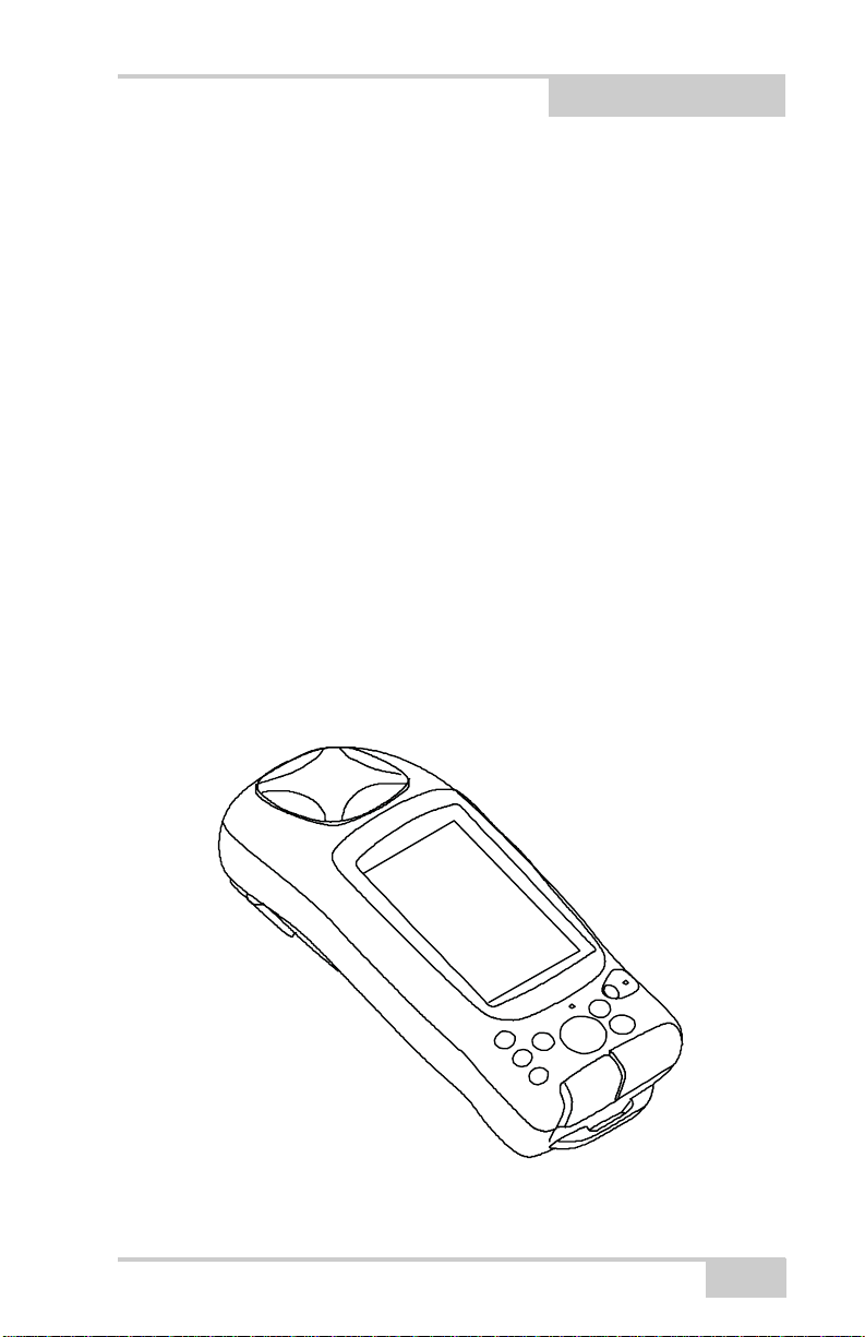
The GMS-2 receiver is a single-frequency, GPS+GLONASS L1
receiver and hand-held controller built to be the most advanced,
compact, and portable receiver for the GIS surveying market. An
integrated electronic compass and digital camera make the GMS-2 an
all-purpose, GIS field mapping unit.
The GMS-2 receiver is a multi-function, multi-purpose receiver
intended for precision markets. Precision markets means markets for
equipment, subsystems, components and software for surveying,
construction, commercial mapping, civil engineering, precision
agriculture and land-based construction and agriculture machine
control, photogrammetry mapping, hydrographic and any use
reasonably related to the foregoing.
The GMS-2 provides the functionality, accuracy, availability, and
integrity needed for fast and easy data collection.
P/N 7010-0752
Figure 1-1. GMS-2
1-1

Introduction
Principles of Operation
Surveying with the right GPS receiver can provide users accurate and
precise positioning, a requirement for any surveying project.
This section gives an overview of existing and proposed Global
Navigation Satellite Systems (GNSS) and receiver functions to help
you understand and apply basic operating principles, allowing you to
get the most out of your receiver.
GNSS Overview
Currently, the following three global navigation satellite systems
(GNSS) offer line-of-site radio navigation and positioning, velocity,
and time services on a global, all-weather, 24-hour scale to any user
equipped with a GNSS tracking receiver on or near the Earth’s
surface:
• GPS – the Global Positioning System maintained and operated by
the United States Department of Defense. For information on the
status of this system, visit the US Naval Observatory website
(http://tycho.usno.navy.mil/) or the US Coast Guard website
(http://www.navcen.uscg.gov/).
• GLONASS – the Global Navigation Satellite System maintained
and operated by the Russian Federation Ministry of Defense. For
information on the status of this system, visit the Ministry of
Defense website (http://www.glonass-center.ru/frame_e.html).
• GALILEO – an upcoming global positioning system maintained
and operated by Galileo Industries, a joint venture of several
European space agencies working closely with the European
Space Agency. Unlike GPS and GLONASS, this is a civil
endeavor and is currently in the development and validation
stage. For information on the status of this system, visit the
Galileo Industries website (http://www.galileo-industries.net).
1-2
GMS-2 Operator’s Manual

Principles of Operation
Despite numerous technical differences in the implementation of
these systems, satellite positioning systems have three essential
components:
• Space – GPS, GLONASS, and GALILEO satellites orbit
approximately 12,000 nautical miles above Earth and are
equipped with a clock and radio. These satellites broadcast digital
information (ephemerides, almanacs, time&frequency
corrections, etc.).
• Control – Ground stations located around the Earth that monitor
the satellites and upload data, including clock corrections and
new ephemerides (satellite positions as a function of time), to
ensure the satellites transmit data properly.
• User – The community and military that use GNSS receivers and
the corresponding satellites to calculate positions.
Calculating Absolute Positions
When calculating an absolute position, a stationary or moving
receiver determines its three-dimensional position with respect to the
origin of an Earth-Center Earth-Fixed coordinate system. To calculate
this position, the receiver measures the distance (called pseudoranges) between it and at least four satellites. The measured pseudoranges are corrected for clock differences (receiver and satellites) and
signal propagation delays due to atmospheric effects. The positions of
the satellites are computed from the ephemeris data transmitted to the
receiver in navigation messages. When using a single satellite system,
the minimum number of satellites needed to compute a position is
four. In a mixed satellite scenario (GPS, GLONASS, GALILEO), the
receiver must lock onto at least five satellites to obtain an absolute
position.
To provide fault tolerance using only GPS or only GLONASS, the
receiver must lock onto a fifth satellite. Six satellites will provide
fault tolerance in mixed scenarios.
P/N 7010-0752
1-3

Introduction
Calculating Differential Positions
DGPS, or Differential GPS, typically uses the measurements from
two or more remote receivers to calculate the difference (corrections)
between measurements, thus providing more accurate position
solutions.
With DGPS, one receiver is placed at a known, surveyed location and
is referred to as the reference receiver or base station. Another
receiver is placed at an unknown, location and is referred to as the
remote receiver or rover. The reference station collects the range
measurements from each GPS satellite in view and forms the
differences (corrections) between the calculated distance to the
satellites and the measured pseudo-ranges to the satellites.
These corrections are then built up to the industry standard (RTCM or
various proprietary standards) established for transmitting differential
corrections and broadcast to the remote receiver(s) using a data
communication link. The remote receiver applies the transmitted
DGPS corrections to its range measurements of the same satellites.
Using this technique, the spatially correlated errors—such as satellite
orbital errors, ionospheric errors, and tropospheric errors—can be
significantly reduced, thus improving the position solution accuracy
of the GPS.
A number of differential positioning implementations exist, including
post-processing surveying, real-time kinematic surveying, maritime
radio beacons, geostationary satellites (as with the OmniSTAR
service), and the wide area augmentation system (WAAS) service.
The real-time kinematic (RTK) method is the most precise method of
real-time surveying. RTK requires at least two receivers collecting
navigation data and communication data link between the receivers.
One of the receivers is usually at a known location (Base) and the
other is at an unknown location (Rover). The Base receiver collects
carrier phase measurements, generates RTK corrections, and sends
this data to the Rover receiver. The Rover processes this transmitted
data with its own carrier phase observations to compute its relative
position with high accuracy, achieving an RTK accuracy of up to 1 cm
horizontal and 1.5 cm vertical.
1-4
GMS-2 Operator’s Manual

Principles of Operation
Essential Components for Quality Surveying
Achieving quality position results requires the following elements:
• Accuracy – The accuracy of a position primarily depends upon
the satellite geometry (Geometric Dilution of Precision, or
GDOP) and the measurement (ranging) errors.
– Differential positioning (DGPS and RTK) strongly mitigates
atmospheric and orbital errors, and counteracts Selective
Availability (SA) signals the US Department of Defense
transmits with GPS signals.
– The more satellites in view, the stronger the signal, the lower
the DOP number, the higher positioning accuracy.
• Availability – The availability of satellites affects the calculation
of valid positions. The more visible satellites available, the more
valid and accurate the position. Natural and man-made objects
can block, interrupt, and distort signals, lowering the number of
available satellites and adversely affecting signal reception.
• Integrity – Fault tolerance allows a position to have greater
integrity, increasing accuracy. Several factors combine to provide
fault tolerance, including:
– Receiver Autonomous Integrity Monitoring (RAIM) detects
faulty GPS and GLONASS satellites and removes them from
the position calculation.
– Five or more visible satellites for only GPS or only
GLONASS; six or more satellites for mixed scenarios.
– Wide Area Augmentation Systems (WAAS, EGNOS, etc.)
creates and transmit, along with DGPS corrections, data
integrity information (for example, satellite health warnings).
– Current ephemerides and almanacs.
Conclusion
This overview simply outlines the basics of satellite positioning. For
more detailed information, visit the TPS website.
P/N 7010-0752
1-5

Introduction
GMS-2 Overview
The GMS-2 is a fully integrated hand-held controller and GPS+
receiver. Included in the system is an electronic compass and digital
camera.
The hand-held controller component of the GMS-2 includes the
Windows® CE operating system and color LCD touch screen.
Integrated Bluetooth® wireless technology allows this system to be a
cable-free controller/receiver for maximum portability. The rugged
casing is durable and built for rugged use.
As a field controller, the GMS-2 can run a full suite of field software
for working with total stations and RTK GPS systems.
The GPS+ receiver component of the GMS-2 can receive and
process GPS+GLONASS L1 signals improving the accuracy of your
survey points and positions. The GPS+ features of the receiver
combine to provide a positioning system accurate for any survey.
Several other features, including multipath mitigation, provide undercanopy and low signal strength reception.
When power is turned on and the receiver self-test completes, the
receiver’s 50 channels initialize and begin tracking visible satellites.
Each of the receiver’s channels can be used to track any one of the
GPS or GLONASS signals. The number of channels available allows
the receiver to track all visible GPS satellites at any time and location.
An internal GPS antenna equipped with a low noise amplifier (LNA)
and the receiver’s radio frequency (RF) device are connected with a
coaxial cable. The wide-band signal received is down-converted,
filtered, digitized, and assigned to different channels. The receiver
processor controls the process of signal tracking.
Once the signal is locked in the channel, it is demodulated and
necessary signal parameters (carrier and code phases) are measured.
Also, broadcast navigation data are retrieved from the navigation
frame.
After the receiver locks on to four or more satellites, it is possible to
solve the so-called “absolute positioning problem” and compute the
receiver’s coordinates (in WGS-84) and the time offset between the
1-6
GMS-2 Operator’s Manual

Getting Acquainted with the GMS-2
receiver clock and GPS time. All this information can be stored in the
the optional SD card and internal flash memory, then processed using
a post-processing software package.
Depending on your options, capabilities of the receiver include:
• Multipath reduction
• Wide area augmentation system (WAAS)
• Single-frequency static, kinematic, and differential GPS (DGPS)
survey modes
• Setting different mask angles
• Setting different survey parameters
The integrated 1.3 megapixel camera is used taking pictures of
surveyed objects or survey sites.
Getting Acquainted with the
GMS-2
The GMS-2 is an integrated field controller and 50-channel GPS
receiver with an internal electronic compass and digital camera. USB
and serial ports, along with Bluetooth® wireless technology provide
communication paths with other devices. An external GPS antenna
connector allows an optional PG-A5 antenna to be connected for
centimeter-level surveys.
The standard GMS-2 package contains the following items:
• GMS-2 integrated receiver/controller activated for GPS L1
signals
• Handstrap and soft case
• USB cable and power converter/adapter cable
• BTManager and GMS Tools factory-installed software
For more details on accessories and options available for the GMS-2,
contact your local Topcon dealer.
P/N 7010-0752
1-7
Introduction
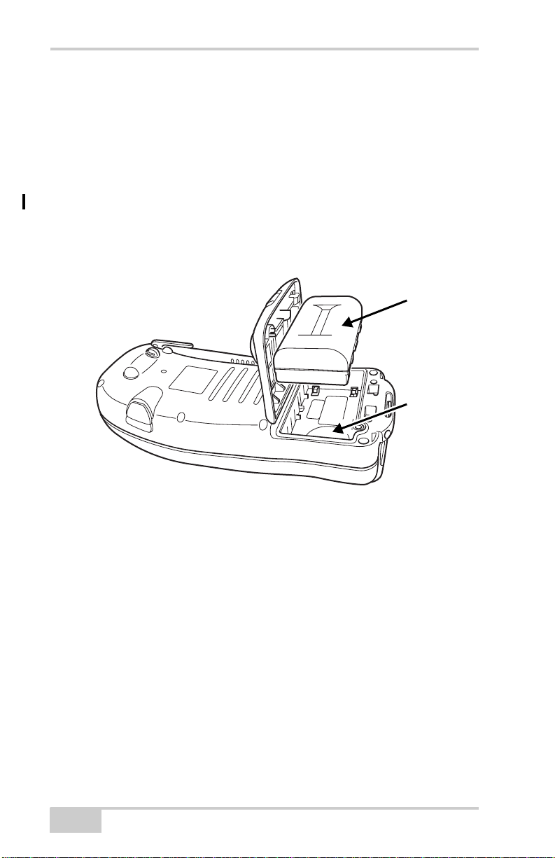
Rechargeable and Backup Batteries
The GMS-2 comes equipped with a rechargeable battery (Figure 1-2)
for powering the unit. The battery can be charged in the unit or in an
optional battery charger. A backup battery is also located in the
battery pocket.
The battery provides seven hours of operation, depending on the
mode of the receiver. Under normal conditions, the backup battery
provides eight to ten years of power backup for data and system
integrity.
Battery
Backup
Battery
Figure 1-2. GMS-2 Battery
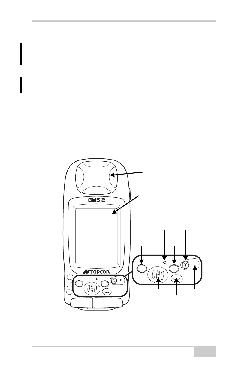
GMS-2 Front
The front of the GMS-2 (Figure 1-3 on page 1-9) is the primary
interface with its components and installed software.
•The internal GPS antenna detects signals from GPS+ satellites
and sends them to the GPS receiver board for processing.
•The display screen and touch panel provides a graphical and
tactile user interface for the unit.
•The power button turns the receiver on and off.
•The ESC (escape) button exits from the current screen or
function.
1-8
GMS-2 Operator’s Manual
Getting Acquainted with the GMS-2
•The ENT (enter) button applies settings, numerical values, and
records points (depending on the settings of internal software).
Pressing this button for one second activates the controller’s
Windows Start menu.
•The Bluetooth LED indicates the level of activity at the
Bluetooth wireless technology module:
– Solid blue light: the module is on and a connection has been
established.
– No light: the module is off.
•The charging LED indicates the level of charge in the battery:
– Green: battery has a full charge.
– Red: battery is charging.
– Red blink: charging error.
Internal GPS
Antenna Cover
P/N 7010-0752
ESC
Display and
Touch Screen
Escape
Button
ESC
ENT
Figure 1-3. GMS-2 Front
Bluetooth
LED
Speaker
Power
Button
Enter
Button
ENT
Charging LED
Microphone
1-9
Introduction
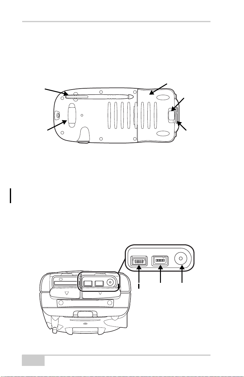
GMS-2 Back
The back of the GMS-2 holds the stylus used for tapping on the
display screen. An elastic strap provides comfortable security while
using the GMS-2. A cover accesses the rechargeable battery and
backup battery.
Stylus
Battery Cover
Battery
Cover
Latch
Hand
Strap
Hook
Figure 1-4. GMS-2 Back
Hand
Strap
Hook
GMS-2 Ports
The GMS-2 has the following three ports:
• USB – used for high-speed connection to a computer via
ActiveSync.
• Serial – used for communication between the unit and an external
device.
• Power – used to connect the GMS-2 to an external power source.
This port can also be used to charge the batteries.
USB Serial Power
1-10
Figure 1-5. GMS-2 Ports
GMS-2 Operator’s Manual

Getting Acquainted with the GMS-2
SD Card Slot
The SD (secure digital) slot provides extended memory for the
controller (Figure 1-6). The data that resides on the SD card can be
accessed via the USB or serial port, or Bluetooth wireless technology.
A secure digital card can be purchased at your local computer supply
store.
Located above the card slot is the software reset button for restarting
the operating system if software is not responding.
Software Reset
Button
SD Card Slot
Figure 1-6. SD Card Slot
Integrated Camera
The integrated 1.3 megapixel camera can be used for taking pictures.
Camera
Figure 1-7. GMS-2 Camera
P/N 7010-0752
1-11

Introduction
External GPS Antenna Connector
The external GPS antenna connector allows an optional external
antenna to be connected to the controller for post-process survey
applications.
External GPS
Antenna
Connector
Figure 1-8. GMS-2 External GPS Antenna Connector
System Cables
The GMS-2 package includes standard communication and power
cables for communicating with the GMS-2 and providing a power
source. Table 1-1 lists the cables included in the standard GMS-2
package.
Table 1-1. GMS-2 Package Cables
Cable Description Cable Illustration
Power cable
Connects the GMS-2 to a
grounded outlet.
U.S. p/n ??
Europe p/n ??
Australia p/n ??
USB cable
Connects the GMS-2 to an
external device (controller
or computer) for high-speed
data transfer and receiver
configuration.
p/n ??
1-12
GMS-2 Operator’s Manual
GMS-2 Software
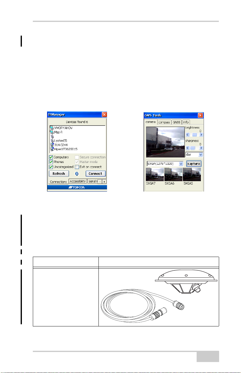
GMS-2 Software
The GMS-2 comes with the following factory-installed software:
• BTManager – a utility that manages and controls the Bluetooth
module inside the GMS-2. BTManager connects the GMS-2 and
other Bluetooth-enabled devices.
• GMS Tools – a utility that manages and controls the camera, and
compass, and GNSS settings.
Figure 1-9. BT Manager and GMS Tools
Optional Accessories
Table 1-2 gives a brief list of optional accessories that can be used
with the GMS-2.
Table 1-2. GMS-2 Optional Accessories
Accessory Illustration
External Antenna and
Cable
When connected to an
external GPS antenna, the
range of the GMS-2 can be
increased.
Antenna p/n ??
Cable p/n ??
P/N 7010-0752
1-13
Introduction
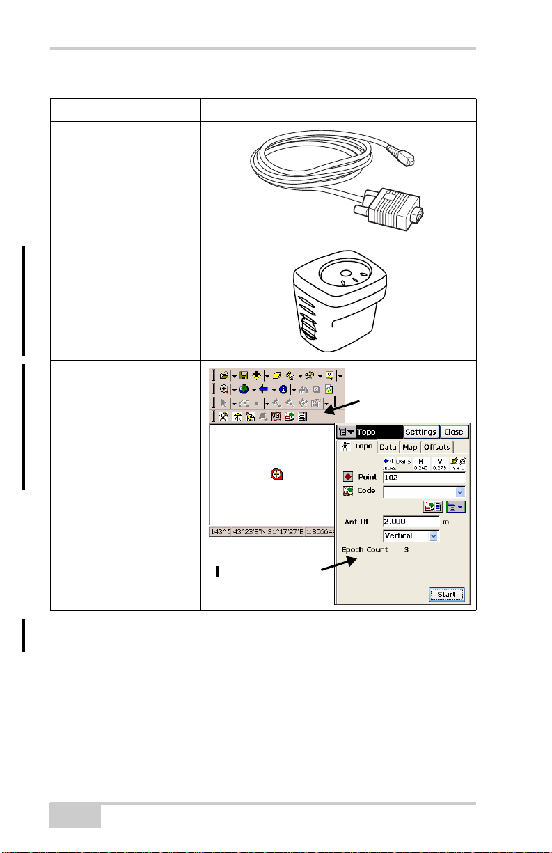
Table 1-2. GMS-2 Optional Accessories (Continued)
Accessory Illustration
Serial cable
Connects the GMS-2 to an
external device (controller
or computer) for data
transfer and receiver
configuration.
p/n ??
BR-1
The BR-1 is a receiver that
detect signals from local
Beacon stations. When
connected to the GMS-2, it
provides correction data.
p/n ??
Optional Software
TopSURV GIS and TopPAD
are GIS surveying software
that can enhance and
expand typical surveys with
GMS-2.
For purchasing, contact
your Topcon dealer.
TopPAD
TopSURV GIS
For more details onteh accessories and package options available for
the GMS-2, contact your local Topcon dealer.
1-14
GMS-2 Operator’s Manual

Option Authorization File (OAF)
Option Authorization File (OAF)
Topcon Positioning Systems issues an Option Authorization File
(OAF) to enable the specific options that customers purchase. An
Option Authorization File allows customers to customize and
configure the receiver according to particular needs, thus only
purchasing those options needed.
Typically, all receivers ship with a temporary OAF that allows it to be
used for a predetermined period of time. When the receiver is
purchased, a new OAF permanently activates desired, purchased
options. Receiver options remain intact when clearing the NVRAM or
resetting the receiver.
The OAF enables the following kinds of functions. For a complete list
of available options and details, visit the TPS website or consult your
TPS dealer.
• Type of signal (standard GPS L1; optional GLONASS L1)
• Update rate standard 1Hz (optional 5, 10, or 20Hz)
• RTK at 1Hz, 5Hz, 10Hz, and 20Hz
• RTCM/CMR Input/Output
•Event marker
• Advanced multipath reduction
• Wide Area Augmentation System (WAAS)
• Receiver Autonomous Integrity Monitoring (RAIM)
P/N 7010-0752
1-15
 Loading...