

Topcon America 5434 Installation Manual

8
$%XCAVATOR)NDICATE3YSTEM
)NSTALLATIONAND#ALIBRATION-ANUAL


POSITIONING SYSTEMS
X-22
Excavator Indicate System
Installation and Calibration
Manual
Part Number 7010-1019
Rev A
©Copyright Topcon Positioning Systems, Inc.
June, 2011
All contents in this manual are copyrighted by Topcon. All rights reserved.
The information contained herein may not be used, accessed, copied, stored,
displayed, sold, modified, published, distributed, or otherwise reproduced
without express written consent from Topcon.

Terms and Conditions
Thank you for buying this Topcon product. This manual has been prepared to assist
you with the care and operation of the product and its use is subject to these Terms
and Conditions and those more fully set forth in the Operator’s/User’s Manual.
Usage and Safety
This product is designed for use by professionals. Always use safety precautions
when operating this or any Topcon product.
Copyrights
All information contained in this Manual is the intellectual property of, and
copyrighted material of TPS. All rights are reserved. You may not use, access, copy,
store, display, create derivative works of, sell, modify, publish, distribute, or allow
any third party access to, any graphics, content, information or data in this Manual
without TPS’ express written consent and may only use such information for the care
and operation of your Product. The information and data in this Manual are a valuable
asset of TPS and are developed by the expenditure of considerable work, time and
money, and are the result of original selection, coordination and arrangement by TPS.
Trademarks
X-22, Topcon, and Topcon Positioning Systems are trademarks or registered
trademarks of TPS.
Other product and company names mentioned herein may be trademarks of their
respective owners.
Disclaimer of Warranty
EXCEPT FOR SUCH WARRANTIES AND LICENSES PROVIDED WITH THE PRODUCT,
THIS MANUAL AND THE PRODUCT ARE PROVIDED “AS-IS”. TOPCON AND ITS
DISTRIBUTORS SHALL NOT BE LIABLE FOR TECHNICAL OR EDITORIAL ERRORS OR
OMISSIONS CONTAINED HEREIN; NOR FOR INCIDENTAL OR CONSEQUENTIAL
DAMAGES RESULTING FROM THE FURNISHING, PERFORMANCE OR USE OF THIS
MATERIAL OR THE PRODUCT.
Please see the Operator’s/User’s Manual for detailed information on warranties and
the license agreement which may apply to the Product.
License Agreement
Use of any computer programs or software supplied by Topcon or downloaded from
the Topcon website in connection with the Product implies acceptance of the Terms
and Conditions here and in the Operator’s/User’s Manual.
Please see the Operator’s/User’s Manual for detailed information on warranties and
the license agreement which may apply to the Product.
ECO#4152

TOC
Table of Contents
Chapter 1
Introduction .......................................................... 1-1
System Components ........................................................ 1-1
Chapter 2
Installation and Calibration ................................. 2-1
Getting Started ................................................................. 2-1
Step 1: Charge the Sensors ........................................ 2-1
Step 2: Attach the Brackets ....................................... 2-2
Bracket for Boom Sensor ................................... 2-2
Bracket for Arm (Stick) Sensor with
Laser Detector ................................................. 2-5
Bracket for Bucket Sensor .................................. 2-6
Bracket for Tilt Bucket Sensor (Optional) ......... 2-10
Step 3: Attach the Mast for the PitchRollCompass ... 2-13
Step 4: Attach the X-22 Display ............................... 2-15
Step 5: Measure the Excavator .................................. 2-17
Step 6: Entering the Sensors on the X-22 Display .... 2-17
Step 7: Attach the Sensors to the Excavator ............. 2-19
Step 8: Calibrate the Sensors ..................................... 2-23
Calibrating the Boom Sensor .............................. 2-23
Calibrating the ArticBoom Sensor (Optional) .... 2-23
Calibrating the PitchRollCompass ...................... 2-23
Calibrating the Stick Sensor ............................... 2-24
Calibrating the Bucket Sensor ............................ 2-24
Calibrating the Tilt Bucket Sensor (Optional) .... 2-25
Step 9: Measure and Calibrate the Buckets ............... 2-25
Finding Your Way Around the Software ......................... 2-26
Tracking .................................................................... 2-26
Wizards ..................................................................... 2-26
How to Return to the Main Menu ............................. 2-27
Before You Start to Dig ................................................... 2-28
P/N 7010-1019
i

Table of Contents
Check that X-22 is Measuring Correctly ................... 2-28
Backup ....................................................................... 2-28
Applications ............................................................... 2-28
Arm (Stick) Sensor with Laser Detector ................... 2-29
Handling Damaged Sensors ....................................... 2-29
Important Information On Use ......................................... 2-30
Charger ...................................................................... 2-30
Sensors ....................................................................... 2-31
X-22 Display and Power Supply ............................... 2-32
Machine and Bucket Measurements ................................ 2-32
Measure Additional Buckets ............................... 2-42
Chapter 3
Troubleshooting .................................................. 3-1
Appendix A
Specifications ...................................................... A-1
X-22 Sensor ...................................................................... A-1
WEEE Directive ............................................................... A-2
Appendix B
Safety Warnings ................................................... B-1
General Warnings ............................................................. B-1
Sensor Warnings .............................................................. B-2
Usage Warnings ............................................................... B-3
Appendix C
Warranty Terms ................................................... C-1
ii
X22 Installation and Calibration Manual
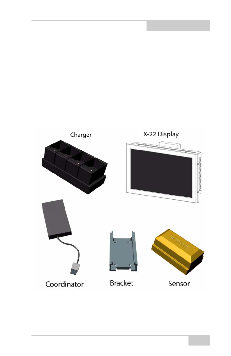
Introduction
Congratulations on your new X-22 System.
System Components
Chapter 1
Measuring and installation equipment is also available separately (not
shown).
P/N 7010-1019
1-1

Notes:
1-2
X-22 Installation and Calibration Manual

Chapter 2
Installation and Calibration
Getting Started
Before you can start using your X-22 System for excavation, you
need to set it up. Read on to find out how to install X-22 on your
excavator in nine simple steps.
Step 1: Charge the Sensors
The first thing you must do is charge the sensors for several hours
(i.e. overnight). The charger’s LEDs may briefly turn on and off as
the sensors go through their charging cycle. This is normal. Leave the
sensors on the charger to ensure a full charge. If the batteries are
completely flat, it takes around 12 hours to charge them fully. Make
sure the contacts on the charger and the sensors are free of debris
before charging.
P/N 7010-1019
Figure 2-1. Battery Charger
2-1
Step 2: Attach the Brackets
NOTICE
NOTICE
Attach the aluminum brackets using the self-tapping screws provided.
The drill and bit for the screws are also included. The drill is 4.6 mm
and the screws Taptite M5x10 have a recessed head.
Rub a little grease or oil onto the screws before
screwing them in.
When determining the location of the sensor
brackets, make sure you allow room to install and
uninstall the sensors onto the brackets.
A weld plates can be purchased separately, if drilling is not possible.
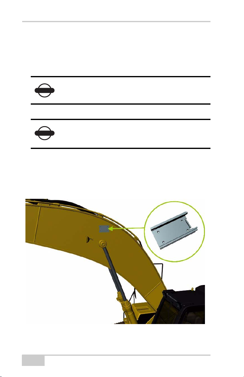
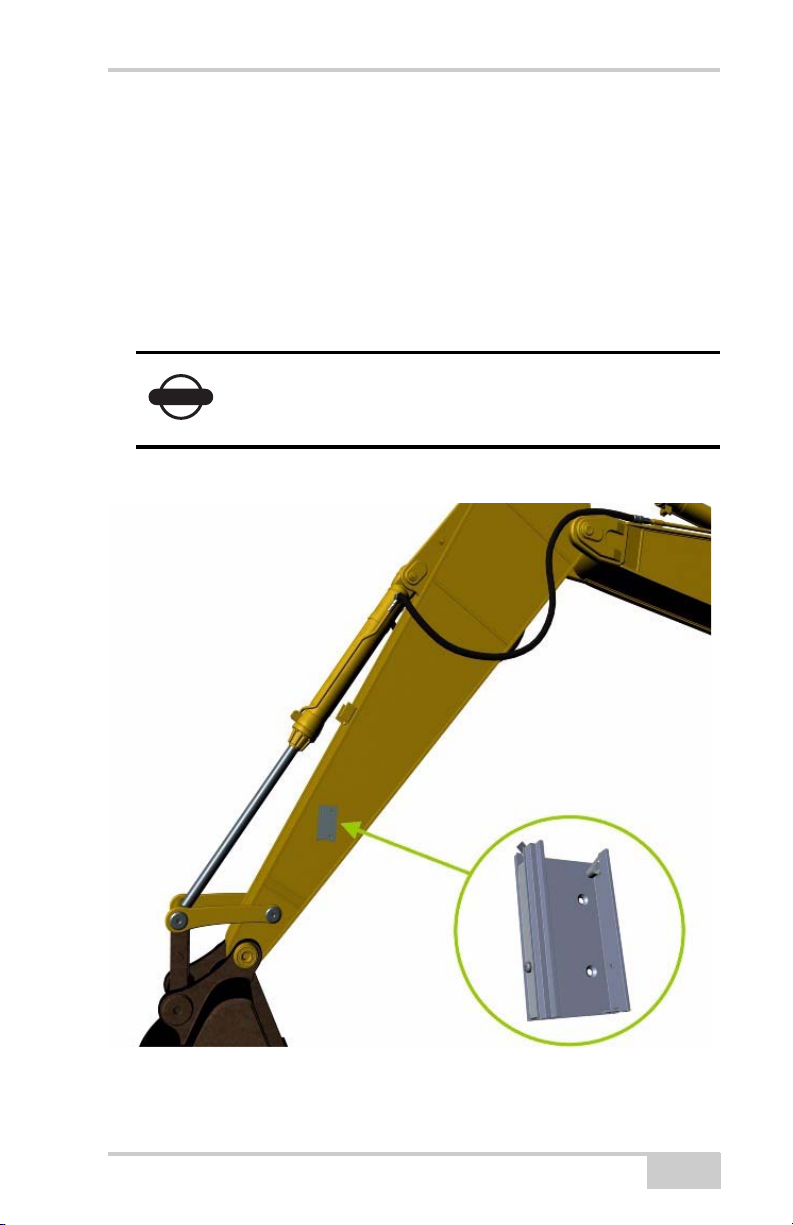
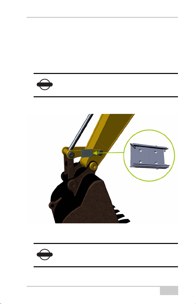
Bracket for Boom Sensor
The bracket for the boom sensor must be attached to the side of the
boom that faces the cab.
2-2
Figure 2-2. Boom Sensor Bracket Location
X-22 Installation and Calibration Manual
Installation and Calibration
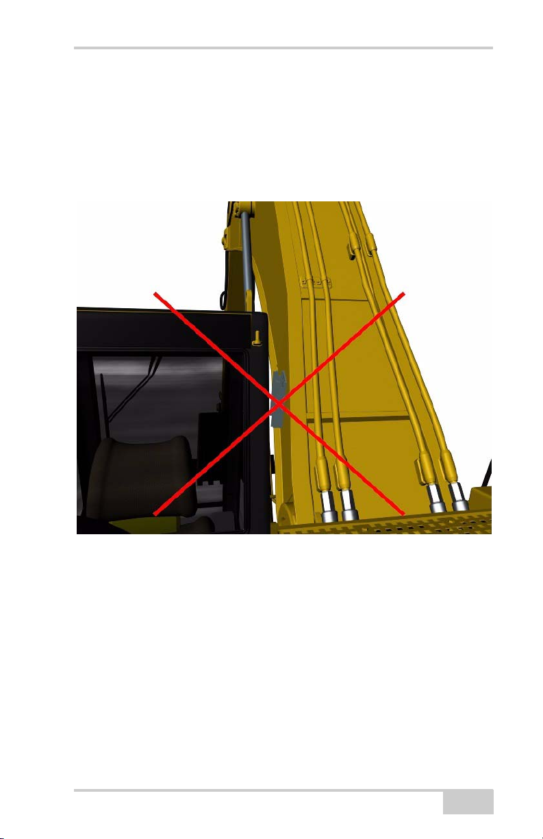
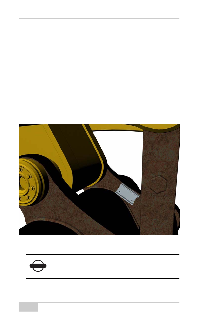
The bracket for the boom sensor must be attached to a face of the
boom that does not slant in relation to the boom bolt. The following
picture shows how the boom is widest down by the boom bolt and
gets narrower towards the center. The bracket must not therefore be
attached in this area.
Figure 2-3. Do Not Install Bracket on Slanted Area of Boom
The bracket for the ArticBoom sensor should be attached to the
articulated (extended) boom, if the machine has one, in the same way.
P/N 7010-1019
2-3
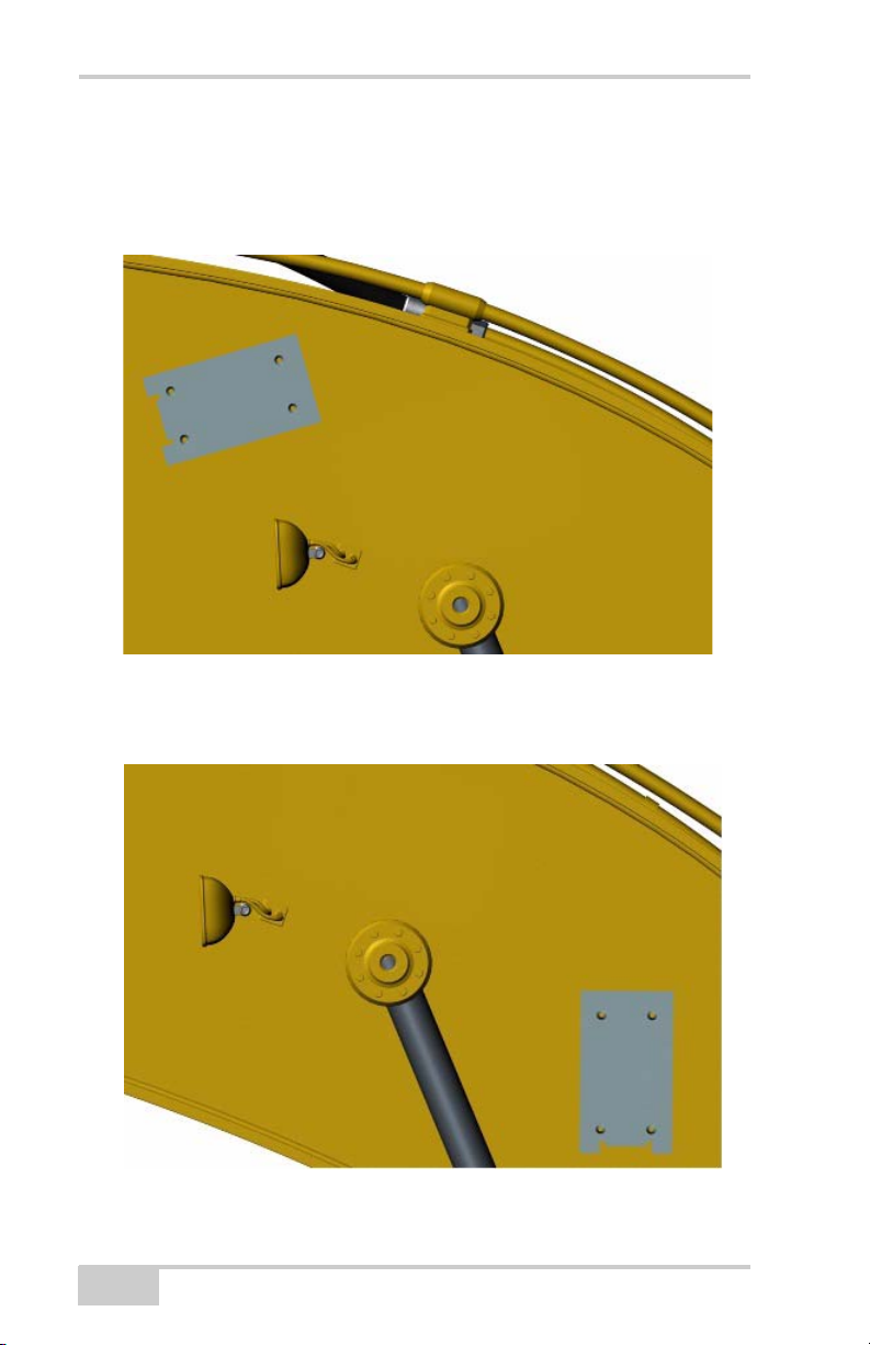
It makes no difference to the wireless communication or angle
measurements for the sensors whether the bracket for the boom
sensor is positioned as shown in Figure 2-4,
Figure 2-4. Boom Sensor Bracket Orientation
or as shown in Figure 2-5.
2-4
Figure 2-5. Boom Sensor Bracket Orientation
X-22 Installation and Calibration Manual
Installation and Calibration
NOTICE
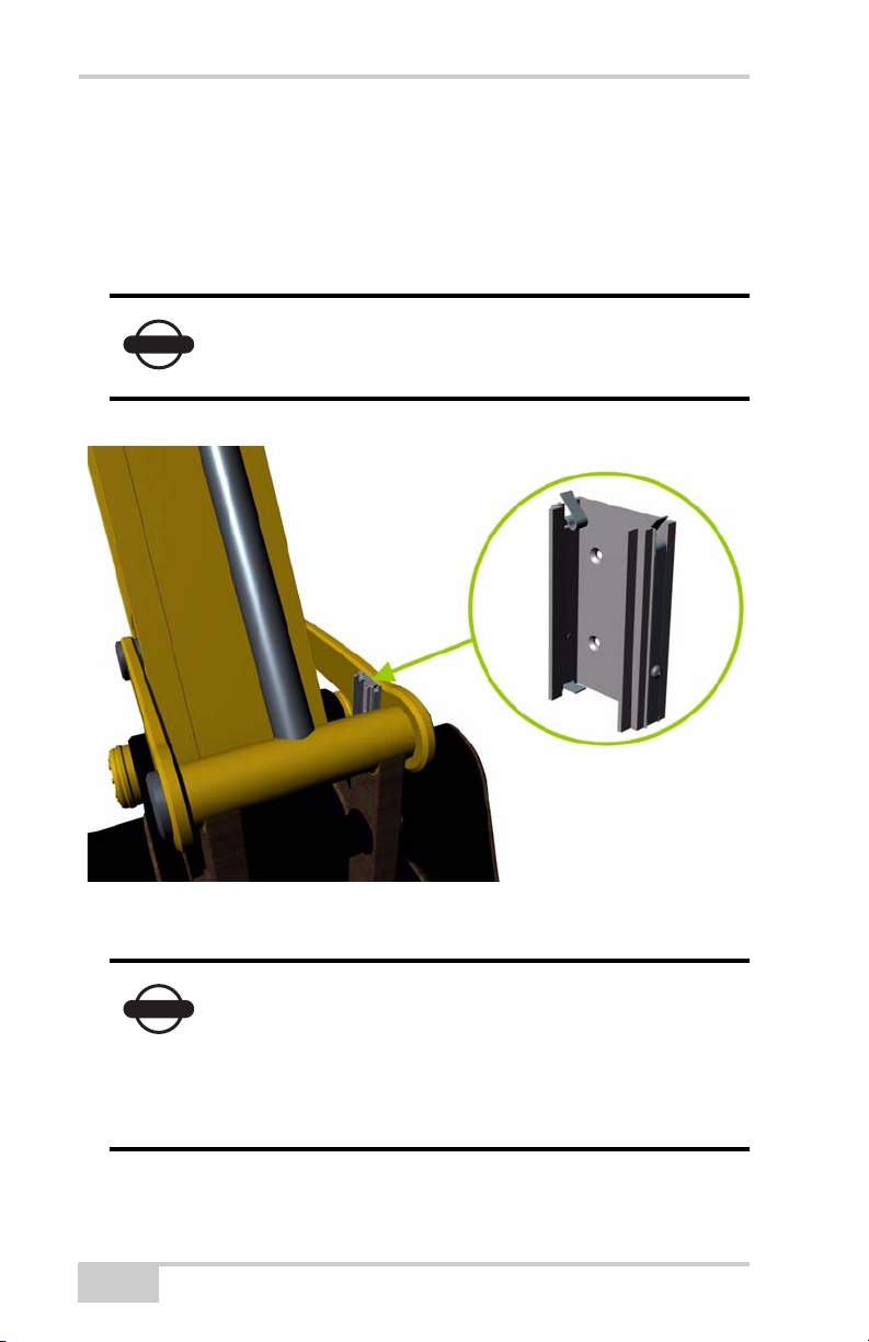
Bracket for Arm (Stick) Sensor with Laser Detector
The bracket for the arm (stick) sensor must be attached to the side of
the arm (stick) that faces the cab.
Position the bracket so that the sensor is roughly vertical when the
laser hits it. Take care not to attach the bracket too high on the arm
(stick) to avoid problems with getting the laser beam to hit the sensor.
Attach the bracket for the arm sensor with the
spring clips at the top so that the sensor slides in
from above.
P/N 7010-1019
Figure 2-6. Arm (Stick) Sensor Bracket Location
2-5
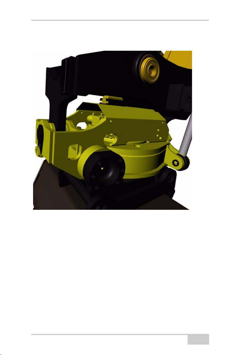
Bracket for Bucket Sensor
NOTICE
The best place to attach the bracket for the bucket sensor depends on
the size of the excavator and if the joints are tight or loose.
It is easiest to make X-22 measure accurately if the bucket sensor is
attached directly on the bucket/quick coupler. This is especially the
case if the joints are loose.
Alternative 1: The inside of the quick coupler/bucket
If the excavator is large enough, the bracket for the bucket sensor can
be attached on the inside of the quick coupler/bucket. Attach the
bracket on the part of the quick coupler/bucket closest to the cab.
2-6
Figure 2-7. Quick Coupler/Bucket Bracket Location - Inside
Fully extend and retract the bucket cylinder before
fitting and make sure that the bracket and the sensor
do not meet any obstructions.
X-22 Installation and Calibration Manual
Installation and Calibration
NOTICE
If the bucket sensor is attached on the inside of the
quick coupler/bucket, the sensor direction of the
bucket sensor must be changed from Normal to
Reverse. Select Main Menu Setup
Hardware Sensors and mark the bucket
sensor. Then select Details. Select Sensor
direction and press Edit.
Alternative 2: The outside of the quick co upler/bucket
The bracket for the bucket sensor can also be attached on the outside
of the quick coupler / bucket. Attach the bracket on the part of the
quick coupler/bucket closest to the cab.
Figure 2-8. Quick Coupler/Bucket Bracket Location - Outside
P/N 7010-1019
2-7
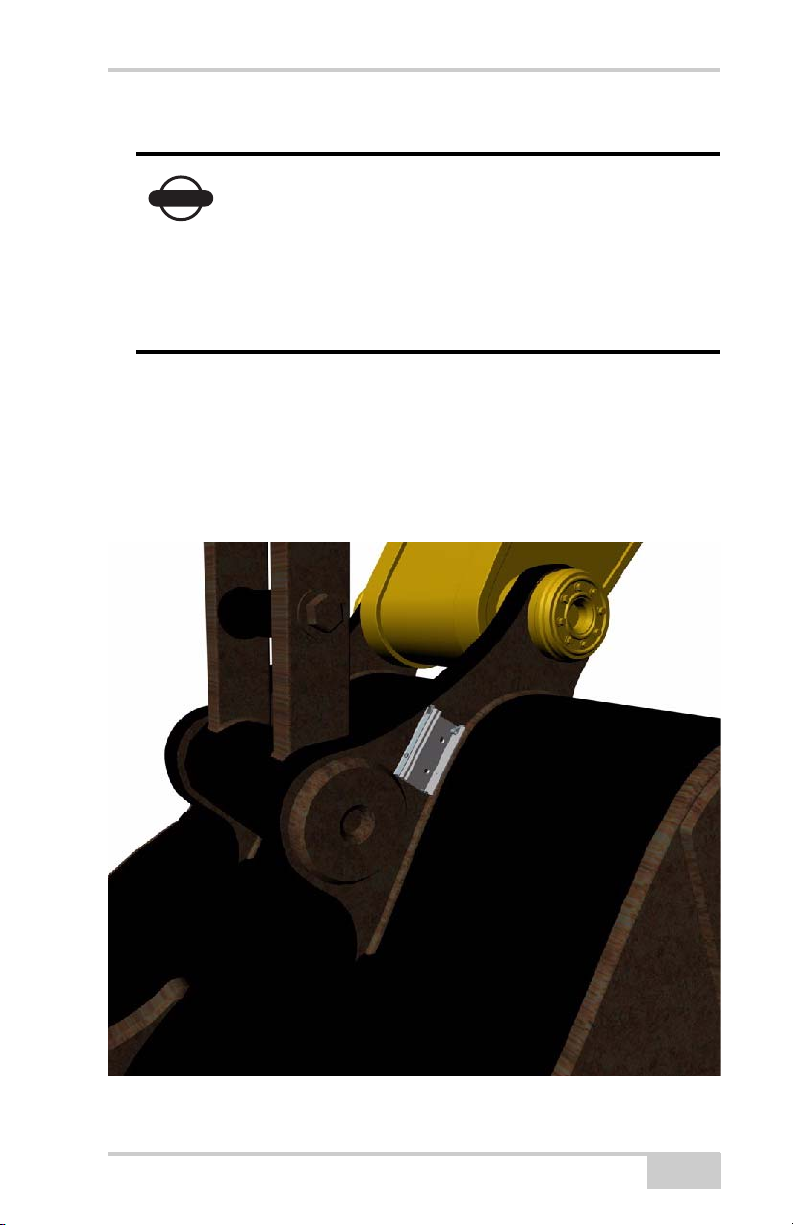
Alternative 3: The inside of the control arm (dog-bone)
NOTICE
NOTICE
If the excavator is large enough and the joints are tight, the bracket for
the bucket sensor can be attached on the inside of the control arm
(dog-bone). Attach the bracket on the control arm closest to the cab.
Fully extend and retract the bucket cylinder before
fitting and make sure that the sensor do not meet
any obstructions.
2-8
Figure 2-9. Inside of Control Arm (Dog-bone)
If the bucket sensor is attached on the inside of the
control arm (dog-bone), the direction of the bucket
sensor must be altered from Normal to Reverse.
Select Main Menu Setup Hardware
Sensors and mark the bucket sensor. Then select
Details. Select Sensor direction, and press Edit.
X-22 Installation and Calibration Manual
Installation and Calibration
NOTICE
NOTICE
Alternative 4: The outside of the control arm (dog-bone)
If the excavator is too small to fit the bracket with the bucket sensor
on the inside of the control arm and the joints are tight, the bracket
can be attached on the outside of the control arm. Attach the bracket
on the control arm closest to the cab.
Fully extend and retract the bucket cylinder before
fitting and make sure that the sensor do not meet
any obstructions.
P/N 7010-1019
Figure 2-10. Outside of Control Arm (Dog-bone)
Attach the bracket with the spring clips on the left
so that the sensor slides into the bracket from the
left.
2-9
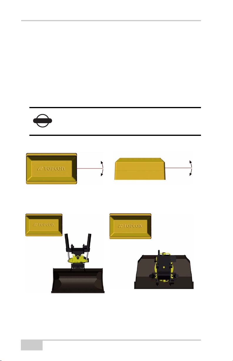
Bracket for Tilt Bucket Sensor (Optional)
NOTICE
The bracket for the tilt bucket sensor must be attached so that the
sensor rotates sideways or lengthways.
Alternative 1: Sideways
When the tilt bucket sensor is installed sideways, the long axis of the
sensor is used to measure how much the bucket is tilted to the side.
The long axis must move as shown in the pictures
below when the bucket is tilted to the side, or else
the sensor will not measure correctly.
Figure 2-11. Sideways Installation
2-10
Figure 2-12. Sideways Installation
X-22 Installation and Calibration Manual
Installation and Calibration
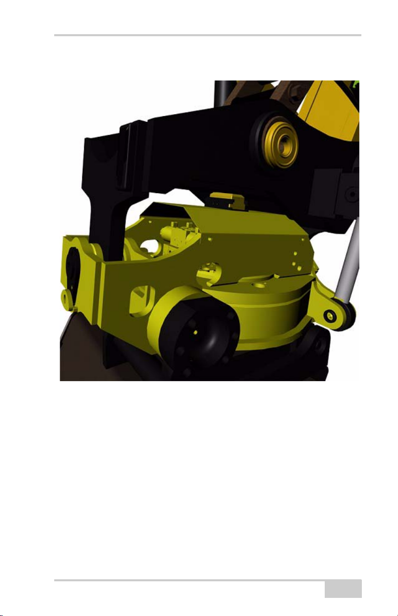
Example of sideways installation on a tilt bucket:
P/N 7010-1019
Figure 2-13. Sideways Installation
2-11
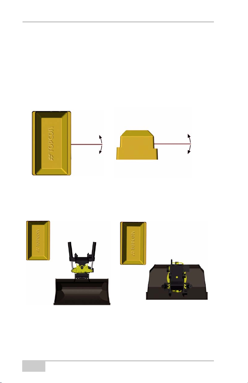
Alternative 2: Lengthways
When the tilt bucket sensor is installed lengthways, the short axis of
the sensor is used to measure how much the bucket is tilted to the
side. Note that the short axis must move as shown in the pictures
below when the bucket is tilted to the side, or else the sensor will not
measure correctly.
Figure 2-14. Lengthways Installation
2-12
Figure 2-15. Lengthways Installation
X-22 Installation and Calibration Manual
Example of lengthways attachment:
Installation and Calibration
Figure 2-16. Lengthways Installation
Step 3: Attach the Mast for the PitchRollCompass
A mast is supplied with X-22 for the PitchRollCompass sensor. We
recommend mounting the mast on the back of the machine’s
counterweight. Position the bracket on top of the mast, parallel with
the tracks of the machine.
The optional welding mast ring (sold separately) is to be welded to
the machine. Bolts and nuts are supplied with the mast. When the
P/N 7010-1019
2-13
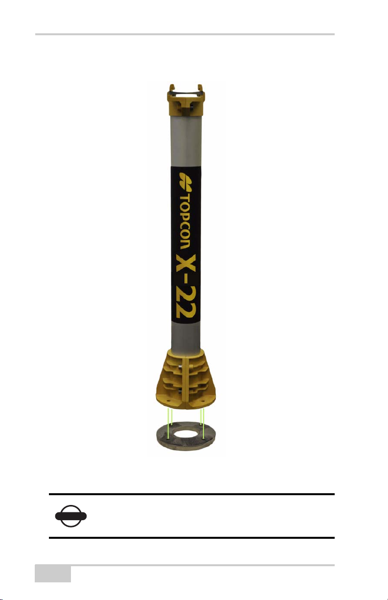
mast ring is in place, attach the aluminium bracket firmly to the
NOTICE
mounting ring with the M8x30 Allen screws provided.
2-14
Figure 2-17. Mast and Mast Ring Installation
Position the mast (or mast ring) so that it holds the
mast steady and vertical on the excavator.
X-22 Installation and Calibration Manual
Installation and Calibration
NOTICE
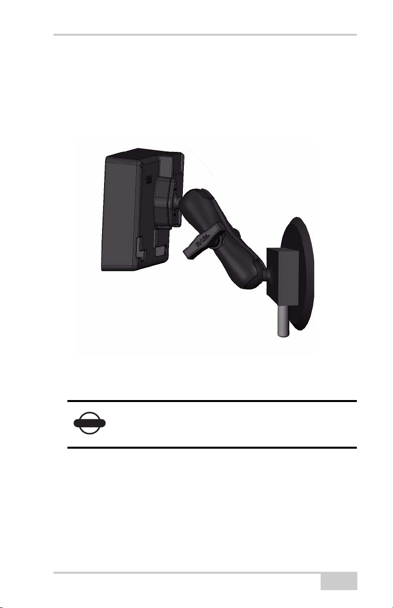
Step 4: Attach the X-22 Display
You can easily attach the X-22 Display to the side window in the cab
using the suction cup provided. Clean the glass before attaching the
suction cup. This prevents air from getting into the suction cup.
P/N 7010-1019
Figure 2-18. X-22 Display - Side View
Check regularly that the suction cup is firmly
attached and take it off when it is not being
watched.
2-15
 Loading...