

Topcon America 100926 User's Manual

Digital UHF II Radio Module
EXTERNAL DESIGN SPECIFICATION
Part Number 7010-xxxx
Rev. A
©Copyright Topcon Positioning Systems, Inc.
December, 2011
All contents in this manual are copyrighted by Topcon Positioning System, Inc. All rights reserved. The information
contained herein may not be used, accessed, copied, stored, displayed, sold, modified, published, or distributed, or
otherwise reproduced without express written consent from Topcon.


Table of Contents
TOC
1 Introduction 1-1
Overview 1-1
Product Features 1-2
Operating Band, Channel Spacing, and Output Power 1-2
Modulation Technique 1-2
Physical Interfaces 1-2
Serial Data Interface 1-2
Link Status Indicators 1-3
Power Interface 1-3
RF Interface 1-3
Bluetooth Interface 1-3
Hardware Architecture 1-4
Functional Requirements 1-4
Electromagnetic Compliance 1-4
Electromagnetic Compatibility 1-5
Shielding Considerations 1-5
Frequency Planning 1-5
Mechanical Considerations 1-6
EMI interferers 1-6
P/N 7010-xxxx
Shock and Vibration 1-6
Thermal Transfer 1-6
i

Table of Contents
Materials 1-6
2 Command Reference 2-1
Introduction 2-1
Intended Audience 2-1
Icons 2-2
Operating Modes 2-2
Firmware Images 2-3
Configuration Files 2-3
Factory configuration file 2-3
Dealer configuration file 2-3
Country configuration file 2-4
Commands 2-5
3 Specifications 3-1
Board Specifications 3-1
Interface Connector 3-4
ii
Digital UHF II EXTERNAL DESIGN SPECIFICATION

Introduction
Chapter 1
Overview
DUHFII is a half duplex, UHF Radio Modem with built-in GSM/GPRS (or CDMA, HSPA) module
and Bluetooth transceiver developed to be integrated in a Topcon receiver. It takes incoming data from
a Topcon receiver through the standard serial port (CMOS/TTL compatible), modulates it with GMSK,
or 4FSK modulations and transmits it at RF power output levels from 10mW/10dBm to 1W/30dBm.
With 4FSK modulation, it will deliver error-free data at up to 19.2 kbps over the air for the 25 kHz
channel spacing and 9.6 kbps for 12.5 kHz.
The carrier frequency is the UHF commercial band of 400 MHz to 470 MHz. Channel spacing at 25
kHz, 20 kHz and 12.5 kHz are supported. The UHF transceiver is also capable of receiving RF signals
through a 50 Ohm impedance external antenna port. These signals are demodulated and output to the
Topcon receiver.
The modem requires a regulated DC voltage power supply from +6 to +14V
current draw of 1.1A at 6V
The incoming data could be also sent over the cellular network using built-in GSM/GPRS (or CDMA,
3G) module if such operation mode is selected.
The radio settings can be done through the built-in Command Line interface (CLI), or through the
configuration and maintenance application software running on the PC – “TRU”.
Note: The cell module option is currently not available. References to the cell module option in this
manual are for future configurations that have not been released.
DC.
DC with a maximum
P/N 7010-xxxx
1-1
Introduction
Product Features
Operating Band, Channel Spacing, and Output
Power
The following are its key benefits:
1. Single radio system covers the whole UHF frequency band from 400 to 470 MHz;
2. User selectable channel spacing (25kHz, 20kHz or 12.5kHz);
3. User selectable Output power level for base unit (10mW/10dBm and 1W/30dBm);
4. Programmable to limit operation to given frequency range or list of channels, given channel
spacing, given output power, RX mode.
Modulation Technique
The design is based on high-level modulation techniques which include:
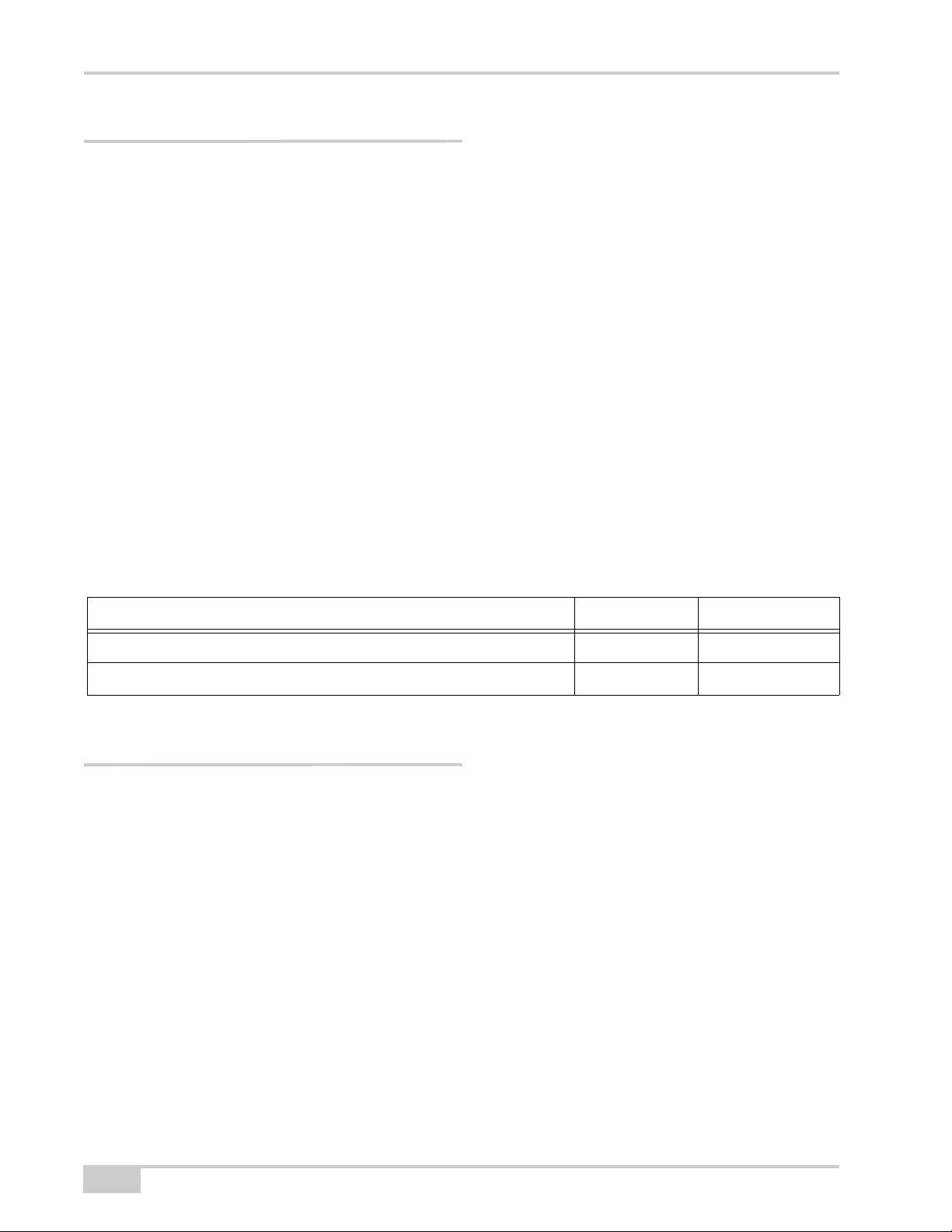
Modulation Technique 12.5 kHz 25 kHz
GMSK – Minimal Shift Keying with Gaussian Filtering 4.8 kbps 9.6 kbps 4.8 kbps 9.6 kbps
4FSK – Four Level Frequency Shift Keying 9.6 kbps 19.2 kbps
9.6 kbps 19.2 kbps
Physical Interfaces
Serial Data Interface
The serial Data Interface can be configured through the software to operate in half and full duplex
operating modes. RTS, CTS, and CD signals should be reserved on-board for future support of full
UART hardware handshake operation. This will provide the support of the wide range of different
standard and none-standard, user specific, Data Link interfaces.
1-2
Digital UHF II EXTERNAL DESIGN SPECIFICATION
Link Status Indicators
WARNING
WARNING
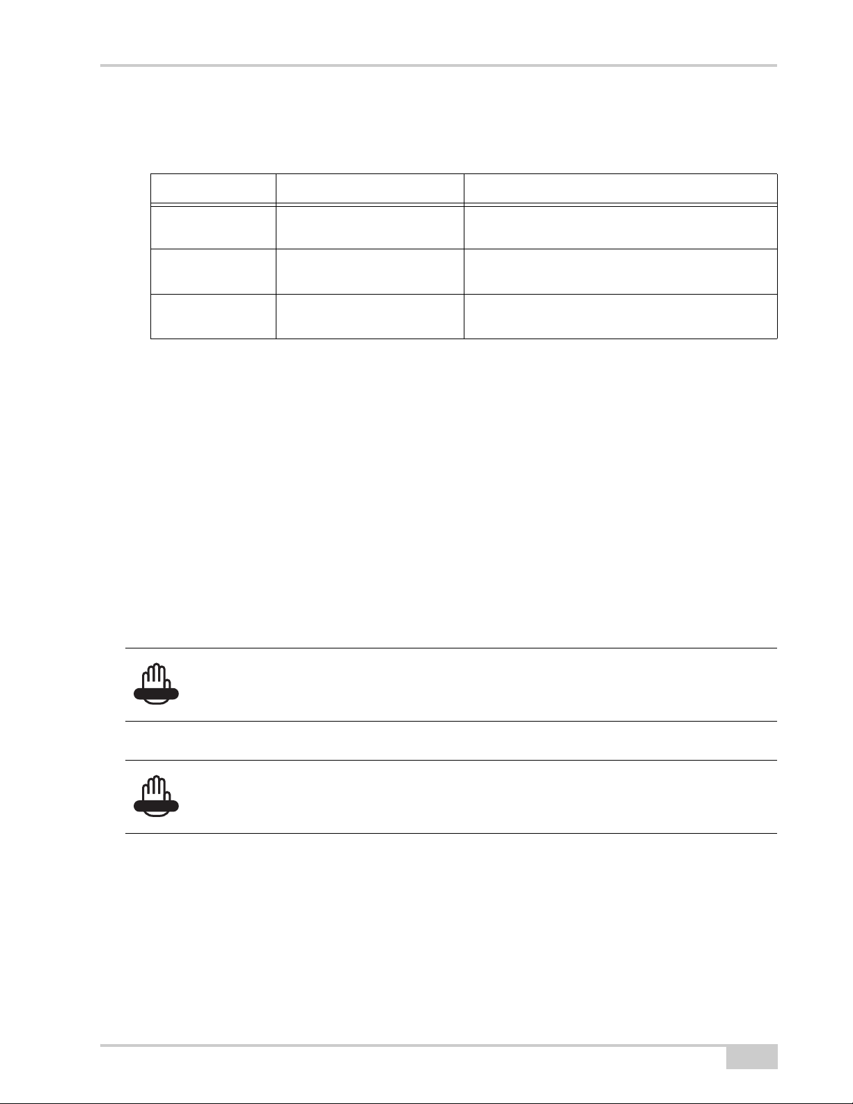
External LED’s are used for Link and Line status indication:
LED Name Color Description
TXA Green Active if modem transmits Data over radio link (min.
RXA Red Active if modem receives Data over radio link (min.
BLUETOOTH Blue Active if modem receives or transmits Data over
Power Interface
The power interface allows connection to an unregulated DC power source. The DC power source
(third party or user supplied) must provide peak 7.0 Watts of DC power between 6 and 14V
power interface is protected against reverse polarity connection, as well as protected against highvoltage transients.
Physical Interfaces
light on 200ms)
light on 200ms)
Bluetooth interface
DC. The
RF Interface
The RF interface is a 50-ohm impedance matched standard MMCX connector as required by
regulation. Switching from UHF to GSM/GPRS (or CDMA) operation mode and vice versa is
provided on RF interface.
Before transmitting, always confirm that the antenna is connected.
Never transmit without the antenna or load connected.
Mismatching of impedance between the DUHF II, antenna, and cable will cause a lesser transmit
power and result in a higher VSWR.
Bluetooth Interface
Bluetooth antenna connector of Radial UMP series (R107003010) is used for Bluetooth antenna
attachment.
P/N 7010-xxxx
1-3
Introduction
NOTICE
Hardware Architecture
Functional Requirements
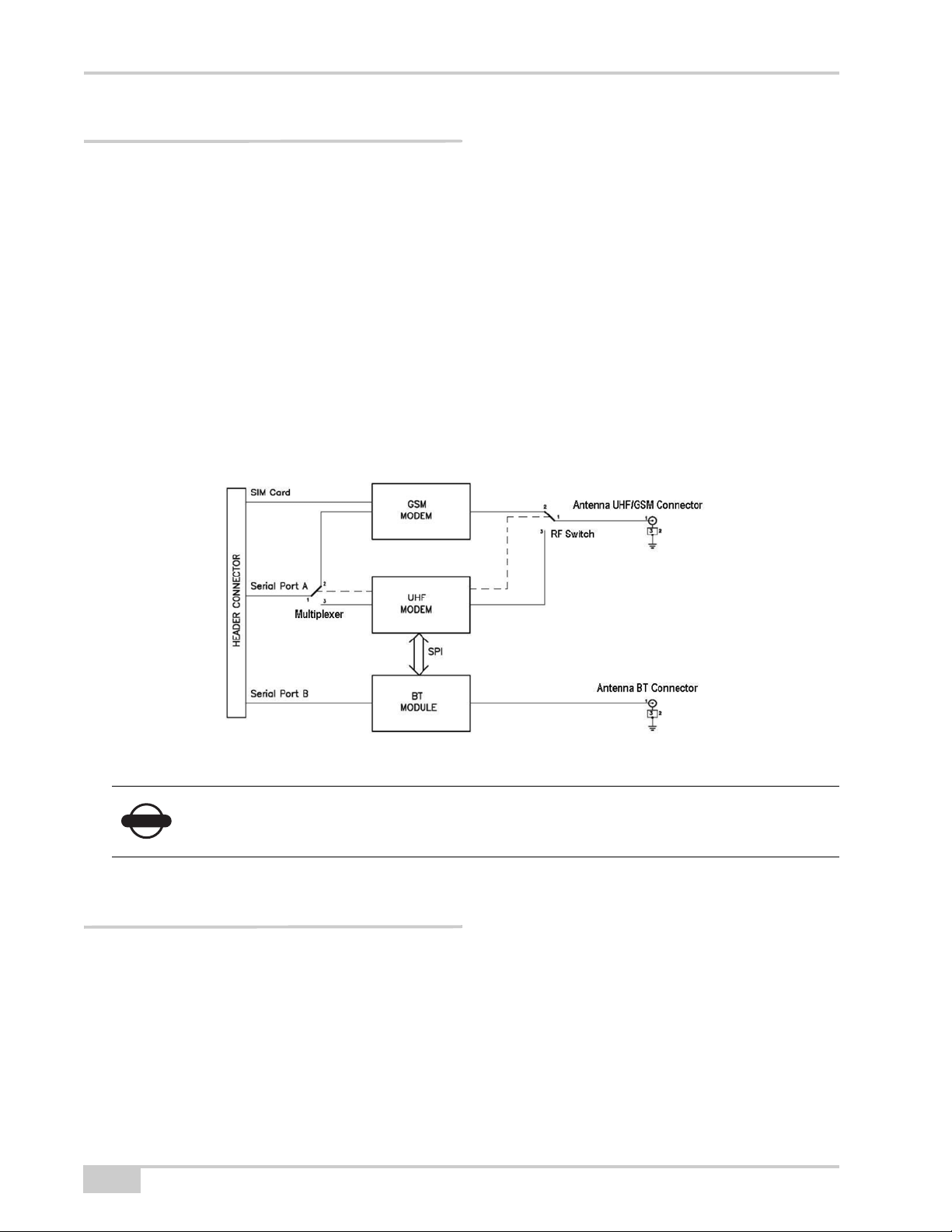
The UHF Modem/Cell/BT Board consists of the following main sections:
• UHF modem Tx/Rx modem;
• GSM/GPRS, 3G, or CDMA modules;
• Bluetooth module.
The block diagram of the DUHFII is presented below. In the figure, consider GSM modem as referring
to either GSM/GPRS or CDMA modules.
The GSM/GPRS (or CDMA) module installation is optional. The mechanical design and software tools
provide easy way for GSM/GPRS module optional installation and configuration.
Electromagnetic Compliance
This device complies with part 15 of the FCC Rules. Operation is subject to the condition that this
device does not cause harmful interference.
1-4
Digital UHF II EXTERNAL DESIGN SPECIFICATION
Changes or modifications not expressly approved by the manufacturer could void the user’s authority
WARNING
WARNING
to operate the equipment.
Installation of Digital UHF II module into device shall comply with section 2.1091 of the FCC Rules.
If not possible to ensure that the separation between the user and the UHF antenna is greater than 30
cm, the user manual shall contain a statement warning the user to stay away from the UHF antenna by
30 cm at least when the UHF radio is operating in transmit mode.
UHF and Bluetooth antennas shall be shielded from the Digital UHF II module by the construction of
the device, so that not to cause harmful interference to the module.
The DUHF II is classified as an intentional radiator of type radio transceiver. Conducted and
radiated emissions of the standard DUHF II transceiver do not exceed the requirements of FCC
part 90. OEM is responsible for full compliance of final product.
Electromagnetic Compatibility
Electromagnetic Compatibility
Shielding Considerations
The DUHF II transceiver is designed to operate in proximity to noise generating circuitry. However,
certain radiated or conducted frequencies may degrade the performance of the DUHF II transceiver or
render it inoperable. When possible, provide well-grounded shielding between circuits that radiate,
such as power supplies, voltage-controlled oscillators, crystal oscillators and the DUHF II transceiver.
Frequency Planning
Radiated and conducted signals to and from the DUHF II transceiver may cause problems due to
interference. Proper attention to frequency planning may reduce interference from radiated or
conducted frequencies that fall within the pass-bands of the filters at the IF frequencies.
It is recommended the use of upfront analysis of the product frequency plan (including harmonics) and
then the use of a spectrum analyzer to determine the potential for interference within the pass-bands of
the various front-end and band pass filters.
Frequencies ranging from 403 to 413 MHz may adversely affect GPS L2.
Do not use these frequencies with a Topcon GNSS receiver.
P/N 7010-xxxx
1-5

Introduction
WARNING
Mechanical Considerations
EMI interferers
The DUHF II transceiver is easily mounted inside new and existing products. The DUHF II transceiver
is specifically designed for operation in harsh environments. For best performance, mount the radio
away from potential EMI radiators and route RF signals apart from digital signals.
It is not recommend the bundling of the antenna interface cable with other signal cables internal
to your product.
Shock and Vibration
Sensitive radio transceivers, such as the DUHF II transceiver, are susceptible to interference due to
mechanical shock and vibration. To reduce the potential for electromechanical interference, a
robust mounting scheme must be used when being integrated into other systems.
Thermal Transfer
The DUHF II transceiver requires additional thermal heat dissipation in order to supply maximum
power out at elevated ambient temperatures and high duty cycles. The DUHF II transceiver has a
thermal sensor and a firmware controlled limit switch. The DUHF II will shut down when the PCB
temperature reaches 100°C to prevent permanent damage to transmitter. The DUHF II will produce
approximately 6 Watts of heat at full RF power out.
Materials
The DUHF II transceiver is housed in a metal shield that is a conductor and is electrically connected to
the ground and signal ground pins.
1-6
Digital UHF II EXTERNAL DESIGN SPECIFICATION

Chapter 2
Command Reference
Introduction
This command reference describes in detail all the commands available in version 1.2a9 of the
DUHFII firmware running on the Digital UHFII modems from Topcon Positioning Systems Inc. This
reference provides a very limited amount of feature descriptions, explanations of the technologies, or
configuration examples. For detailed information about the various features and technologies
supported by DUHFII modems, see “Introduction” on page 1-1.
Intended Audience
This reference is intended for system engineers, system designers, and programmers who are
communicating with the DUHFII modems using the command interface, and are designing or
implementing applications that use the DUHFII commands.
P/N 7010-xxxx
2-1

Command Reference
Icons
This reference includes icons that appear in the left margin and are designed to help you clearly
identify operating mode in which you can apply a particular command. The following icons are used
throughout this reference:
Keys Operating Mode
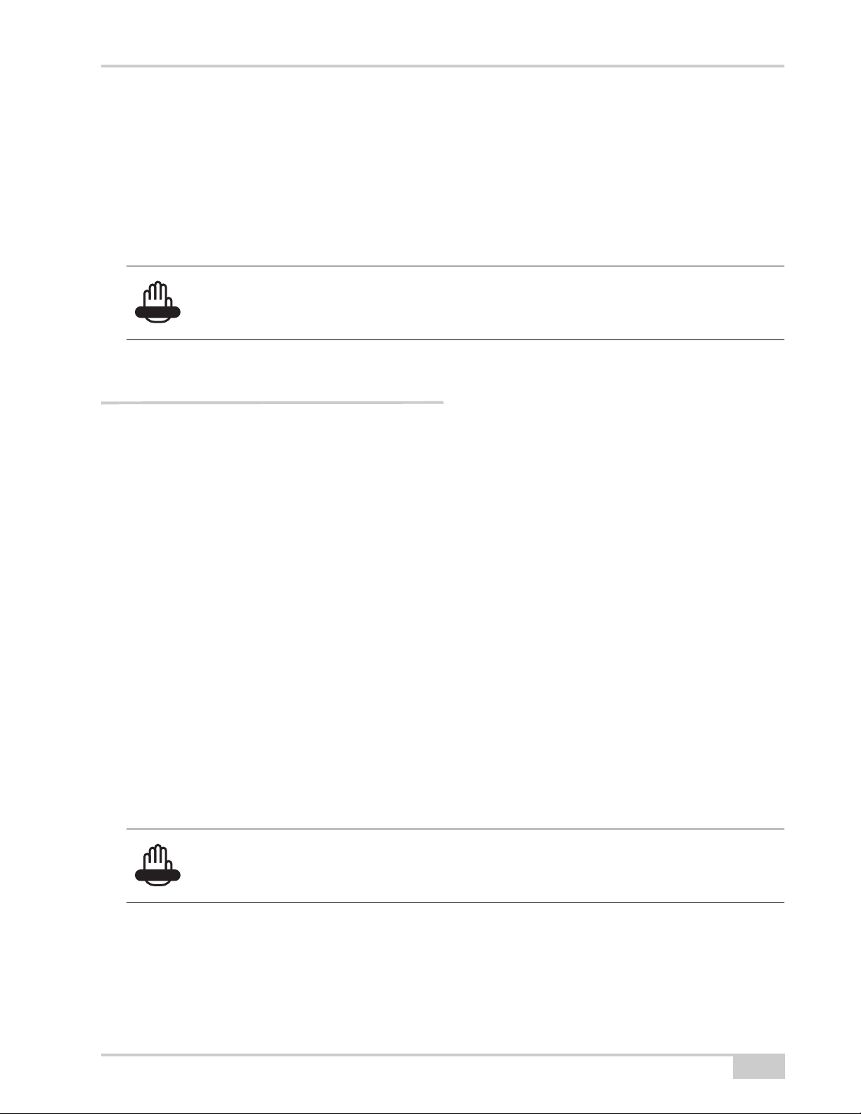
Command applies in Factory mode
only.
Command applies in Dealer mode
only.
Operating Modes
The DUHFII modem can be operated in ether of the following modes:
• Factory – This mode is intended for the factory floor only. In this mode, factory personnel can
calibrate the modem and upload the factory firmware image and bootloader to it. The modem
enters Factory mode initially and brings out of this mode after a normal country configuration file
is uploaded.
• Dealer – This mode is intended for the dealers. In this mode, a dealer can load a dealer
configuration file to the modem. This file contains a customized set of parameters that the dealer
have selected to run on the modem. For details about the parameters available in this file, see
“Configuration Files” on page 2-3. The modem enters Dealer mode after a country configuration
file and brings out of this mode after a normal dealer configuration file is uploaded. Once the
modem brings out of Dealer mode, it automatically goes into User mode.
Command applies in User mode only.
2-2
• User – This mode is intended for the end-users. In this mode, a user can apply the parameters
available in the dealer configuration file to the modem. For details about the parameters available
in the dealer configuration file, see “Configuration Files” on page 2-3. Note that every DUHFII
modem shipped to an end-user must be in User mode.
Digital UHF II EXTERNAL DESIGN SPECIFICATION

Firmware Images
The DUHFII modem stores two firmware images; a factory and a user image.
• The factory image is the factory-installed firmware that is permanently available on the DUHFII
modem.
• The user image is the user-installed firmware that normally controls all modem operations,
including its normal boot process. If the modem boot process with the user image fails for any
reason, the modem can be booted with the factory image.
Initially, the modem is initialized with factory and user firmware images which are identical.
Firmware Images
Configuration Files
The DUHFII modem stores three configuration files, specifically: factory configuration file, dealer
configuration file, and country configuration file.
Factory configuration file
This file stores modem calibration parameters and is generated only by the test bench on the factory
floor.
Dealer configuration file
The dealer configuration file limits the selection of frequencies, channel spacings and maximum
output power for an end user. Note that the allowed frequencies are defined by a list of specified
frequencies, not by the range.
typedef struct
{
unsigned int freq; // Hz
short reserved; // = 0
char spacing; // 0 - 25kHz, 1 - 12.5 kHz, 2 - 20 kHz
char max_power; // dBm
} t_U_Channels;
P/N 7010-xxxx
typedef union
2-3

Command Reference
{
t_U_Channels chan;
unsigned int crc32;
} t_User_Channels;
typedef struct
{
unsigned int DCFG; // 0x47464344 = DCFG signature
unsigned short version; // = 0
unsigned short number_of_channels; // 0-64 variable size structure
char callsign[32]; // zero terminated string
t_User_Channels item[64];
unsigned int crc32; // The CRC32 is a standard CRC with a
} t_DealerConfig;
// polynomial of 0x04C11DB7, an initial
// value of 0xFFFFFFFF and an inverted
// output. The same algorithm is used in
// ZIP and RAR archives as well as in the
// ITU V.42 standard.
Country configuration file
The country configuration file limits the range of allowed frequencies depending on the allocation of
RF bands in a specific country (region). It allows up to four contingent frequency ranges, each with its
own maximum output power and channel spacings.
typedef struct
{
unsigned int start_freq; // Hz, 0 if unused
unsigned int stop_freq; // Hz, 0 if unused
unsigned int spacing_enable_mask; // 0x00000001 - 25kHz,
short reserved1; // = 0
char reserved2; // = 0
char max_power; // dBm, 10-30
} t_Freq_Ranges;
typedef struct
{
unsigned int CCFG; // 0x47464344 = CCFG signature
unsigned short version; // = 0, incompatible modifications will have
unsigned short reserved; // = 0
t_Freq_Ranges band[4]; // fixed size, not used ranges should be
// 0x00000002 - 12.5kHz,
// 0x00000004 - 20kHz
// different number
// zero
2-4
Digital UHF II EXTERNAL DESIGN SPECIFICATION

unsigned int crc32; // The CRC32 is a standard CRC with a
} t_CountryConfig;
Commands
This section lists the commands and subcommands supported by the DUHFII modem.
Commands
// polynomial of 0x04C11DB7, an initial
// value of 0xFFFFFFFF and an inverted
// output. The same algorithm is used in
// ZIP and RAR archives as well as in the
// ITU V.42 standard.
DATAMODE
Description: Switches the modem to data mode.
Access: write-only
Subcommands: This command has no subcommands.
If the modem does not receive a command within 60
seconds, it will enter data mode.
Usage
Guidelines:
When the modem generates test signals (TSTSGL
1...TSTSGL 6), the modem will remain in command
mode until you disable the test signals with the
command TSTSGL 0.
Command
Examples:
History:
++++
DATAMODE
This command was introduced in the first release of
firmware.
Description: Switches the modem to command mode.
Access: write-only
Subcommands: This command has no subcommands.
The guard time is 20 ms.
Usage
Guidelines:
You can also enter command mode by asserting a DTR
line. To switch back to data mode, you must deassert the
DTR line. A 60-seconds timeout is disabled while the
DTR line is asserted.
P/N 7010-xxxx
2-5

Command Reference
Description: Switches the modem to command mode.
Access: write-only
Command
Examples:
History:
LINK
++++
This command was introduced in the first release of
firmware.
Description: Reports the current configuration of the RF data link.
Access: read-only
Subcommands:
Usage
Guidelines:
Command
Examples:
History:
MAP, RFSW, MOD, PROT, PWRB, PWRW, SPACE,
CHAN, UCHAN, FREQ, SCRAM, FEC
This command has no usage guidelines.
LINK
LINK SPACE 0
This command was introduced in the first release of
firmware.
LINK Subcommands:
MAP
Description: Reports the channel map from the dealer list.
Access: read-only
Usage
Guidelines:
Command
Examples:
History:
RFSW
This subcommand has no usage guidelines.
LINK MAP
This subcommand was introduced in the first release of
firmware.
Description: Specifies the datalink type being used by the modem.
Access: read & write
Va lu e s:
0 – UHF
1 – GSM/GPRS
Usage
Guidelines: This subcommand has no usage guidelines.
2-6
Digital UHF II EXTERNAL DESIGN SPECIFICATION
 Loading...