

Topcon America 090521, 090511 Users Manual
HiPerII Chapter 1
Introduction
The HiPerII receiver is a multi-frequency, GPS+ receiver built to be the most advanced and
compact receiver for the surveying market. The receiver is a multi-function, multi-purpose
receiver intended for precision markets.
Precision markets means markets for equipment, subsystems, components and software for
surveying, construction, commercial mapping, civil engineering, precision agriculture and
land-based construction and agriculture machine control, photogrammetry mapping,
hydrographic and any use reasonably related to the foregoing.
The HiPerII can receive and processes multiple signal types ( including the latest GPS L1, L2,
C/A, L2C GLONASS L1, L2, C/A signals ) improving the accuracy and reliability of the survey
points and positions, especially under difficult jobsite conditions. The multifrequency and
GPS+ features of the receiver combine to provide a positioning system accurate for any survey.
Several other features, including multipath mitigation, provide under-canopy and low signal
strength reception. The receiver provides the functionality, accuracy, availability, and integrity
needed for fast and easy data collection.
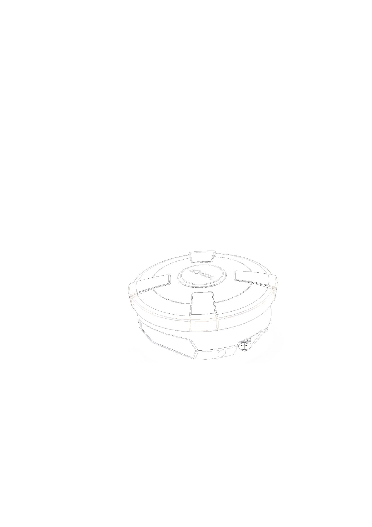
Figure 1-1. HiPerII Receiver
Principles of Operation
Surveying with the right GPS receiver can provide users accurate and precise positioning, a
requirement for any surveying project. This section gives an overview of existing and
proposed Global Navigation Satellite Systems ( GNSS ) and receiver functions so that basic
operating principles can be applied.
HiPerII Chapter 1

HiPerII Chapter 1
GNSS Overview
Currently, the following two global navigation satellite systems ( GNSS ) offer line-of-site radio
navigation and positioning, velocity, and time services on a global, all-weather scale to any user
equipped with a GNSS tracking receiver on or near the Earth's surface:
GPS - the Global Positioning System maintained and operated by the United States
Department of Defense. For information on the status of this system, visit the US Naval
Observatory website ( http://tycho.usno.navy.mil/ ) or the US Coast Guard website
( http://www.navcen.uscg.gov/ ).
GLONASS - the Global Navigation Satellite System maintained and operated by the Russian
Federation Ministry of Defense. For information on the status of this system, visit the
Coordinational Scientific In-formation Center website ( http://www.glonass-ianc.rsa.ru/ ).
Despite numerous technical differences in the implementation of these systems, satellite
positioning systems have three essential components:
Space - GPS and GLONASS satellites orbit approximately 12,000 nautical miles above Earth
and are equipped with a clock and radio. These satellites broadcast ranging signals and
various digital information ( ephemerides, almanacs, time and frequency corrections, and
so forth ).
Control - Ground stations located around the Earth that monitor the satellites and upload
data, including clock corrections and new ephemerides ( satellite positions as a function of
time ), to ensure the satellites transmit data properly.
User - The community and military that use GNSS receivers to calculate positions.
Calculating Absolute Positions
When calculating an absolute position, a stationary or moving receiver determines its
three-dimensional position with respect to the origin of an Earth-Center Earth-Fixed coordinate
system. To calculate this position, the receiver measures the distance ( called pseudo-ranges )
between it and at least four satellites.
The measured pseudo- ranges are corrected for clock differences ( receiver and satellites ) and
signal propagation delays due to atmospheric effects. The positions of the satellites are
computed from the ephemeris data transmitted to the receiver in navigation messages. When
using a single satellite system, the minimum number of satellites needed to compute a position
is four. In a mixed satellite scenario ( GPS, GLONASS ), the receiver must lock onto five or
more satellites to account for the different time scales used in these systems and to obtain an
absolute position.
HiPerII Chapter 1

HiPerII Chapter 1
Calculating Differential Positions
DGPS, or Differential GPS, is a relative positioning technique where the measurements from two
or more remote receivers are combined and processed using sophisticated algorithms to
calculate the receivers' relative coordinates with high accuracy. DGPS accommodates various
implementation techniques that can be classified according to the following criteria:
The type of GNSS measurements used, either code-phase differential measurements or
carrier-phase differential measurements
If real-time or post-mission results required. Real-time applications can be further divided
according to the source of differential data and communication link used.
With DGPS in its most traditional approach, one receiver is placed at a known, surveyed location
and is re ferred to as the referen ce receiver or base station. Another receiver is placed at an
unknown location and is referred to as the remote receiver or rover. The reference station
collects the code-phase and carrier-phase measurements from each GNSS satellite in view.
For real-time applications, these measurements and the reference station coordinates are
then built up to the industry standard RTCM - or various proprietary standards established
for transmitting differential data - and broadcast to the remote receiver ( s ) using a data
communication link. The remote receiver applies the transmitted measurement
information to its observed measurements of the same satellites.
For post-mission applications, the simultaneous measurements from reference and rover
stations are normally re-corded to the receiver's internal memory ( not sent over
communication link ). Later, the data are downloaded to computer, combined, and
processed. Using this technique, the spatially correlated errors - such as satellite orbital
errors, ionospheric errors, and tropospheric errors - can be significantly reduced, thus
improving the position solution accuracy.
A number of differential positioning implementations exist, including post-processing surveying,
real-time kinematic surveying, maritime radio beacons, geostationary satellites ( as with the
OmniSTAR service ), and satellite based augmentation systems ( WAAS, EGNOS, MSAS ).
The real-time kinematic (RTK) method is the most precise method of real-time surveying. RTK
requires at least two receivers collecting navigation data and communication data link between
the receivers. One of the receivers is usually at a known location ( Base ) and the other is at
an unknown location ( Rover ). The Base receiver collects carrier phase measurements,
generates RTK corrections, and sends this data to the Rover receiver. The Rover processes this
transmitted data with its own carrier phase observations to compute its relative position with
high accuracy, achieving an RTK accuracy of up to 1.0 cm horizontal and 2.0 cm vertical.
HiPerII Chapter 1

HiPerII Chapter 1
Essential Components for Quality Surveying
Achieving quality position results requires the following elements:
Accuracy - The accuracy of a position primarily depends upon the satellite geometry
( Geometric Dilution of Precision, or GDOP ) and the measurement (ranging) errors.
Differential positioning ( DGPS and RTK ) strongly mitigates atmospheric and orbital
errors, and counteracts Selective Availability ( SA ) signals the US Department of
Defense transmits with GPS signals.
The more satellites in view, the stronger the signal, the lower the DOP number, the
higher positioning accuracy.
Availability - The availability of satellites affects the calculation of valid positions. The
more visible satellites available, the more valid and accurate the position. Natural and
man-made objects can block, interrupt, and distort signals, lowering the number of
available satellites and adversely affectin g signal reception.
Integrity - Fault tolerance allows a position to have greater integrity, increasing accuracy.
Several factors combine to provide fault tolerance, including:
Receiver Autonomous Integrity Monitoring ( RAIM ) detects faulty GNSS satellites and
removes them from the position calculation .
Five or more visible satellites for only GPS or only GLONASS; six or more satellites
for mixed scenario
Satellite Based Augmentation Systems ( WAAS, EGNOS, and so on ) creates and
transmit, along with DGPS corrections, data integrity information ( for example,
satellite health warnings ).
Current ephemerides and almanacs.
Conclusion
This overview simply outlines the basics of satellite positioning. For more detailed information,
visit the Sokkia Topcon website.
Receiver Overview
When power is turned on and the receiver self-test completes, the receiver's 72 channels
initialize and begin tracking visible satellites. Each of the receiver's channels can be used to
track any one of the GPS or GALILEO signals. The number of channels available allows the
receiver to track all visible global positioning satellites at any time and location.
HiPerII Chapter 1

HiPerII Chapter 1
An internal GPS+ antenna equipped with a low noise amplifier ( LNA ) and the receiver's radio
frequency ( RF ) device are connected with a co-axial cable. The wide-band signal received is
down-converted, filtered, digitized, and assigned to different channels. The receiver processor
controls the process of signal tracking.
Once the signal is locked in the channel, it is demodulated and necessary signal parameters
( carrier and code phases ) are measured. Also, broadcast navigation data are retrieved from
the navigation frame.
After the receiver locks on to four or more satellites, its absolute position in WGS-84 and the
time offset between the receiver clock and GPS time are computed. This information and the
measurement data can be stored in the optional SD card and downloaded later onto a computer,
then processed using a post-processing software package. When the receiver operates in RTK
mode, raw data measurements can also be recorded into the receiver's internal memory. This
allows the operator to double check real-time results obtained in the field.
Depending on your options, capabilities of the receiver include:
Satellite based augmentation systems ( WAAS, EGNOS, and so forth ).
Adjustable phase locked loop ( PLL ) and delay lock loop ( DLL ) parameters
Dual- or multi-frequency modes, including static, kinematic, real-time kinematic ( RTK ),
and differential GPS ( DGPS ) survey modes ( DGPS modes include static, kinematic, and
RTK )
Auto data logging
Setting different mask angles
Setting different survey parameters
Static or dynamic modes
Getting Acquainted
The HiPerII is a 72-channel GPS receiver, which includes the following:
External, detachable batteries
One data ports
Interface for controlling and viewing data logging
External memory card slot
Internal radio modem
Bluetooth wireless technology module
Optional GSM/GPRS module
Optional CDMA module ( only with the Digital UHF radio modem )
HiPerII Chapter 1
 Loading...