

RE-S1
915+ Spread Spectrum Radio Repeater
Operator’s Manual

POSITIONING SYSTEMS
RE-S1 Operator’s Manual
Part Number 7010-0780
Rev. A
©Copyright Topcon Positioning Systems, Inc.
September, 2006
Terms and Conditions
Thank you for buying this Topcon product. This document has been prepared to assist you
with the care and operation of the product and its use is subject to these Terms and
Conditions and those more fully set forth in the Operator’s, User’s, Instruction, or
Reference Manual.
Copyrights and Trademarks
The information in this manual is a copyright of Topcon and is for use only with the
product. HiPer, RE-S1, and Topcon are trademarks or registered trademarks of Topcon
Positioning Systems, Inc.
Other product and company names mentioned herein may be trademarks of their
respective owners.
Disclaimer of Warranty and License Agreement
Please see the Operator’s/User’s/Instruction/Reference Manual for detailed information on
warranties and the license agreement which may apply to the Product.
EXCEPT FOR SUCH WARRANTIES AND LICENSES, THIS MANUAL AND THE
PRODUCT ARE PROVIDED “AS-IS”. TOPCON AND ITS DISTRIBUTORS SHALL
NOT BE LIABLE FOR TECHNICAL OR EDITORIAL ERRORS OR OMISSIONS
CONTAINED HEREIN; NOR FOR INCIDENTAL OR CONSEQUENTIAL
DAMAGES RESULTING FROM THE FURNISHING, PERFORMANCE OR USE OF
THIS MATERIAL OR THE PRODUCT.
Use of any computer programs or software supplied by Topcon or downloaded from the
Topcon website in connection with the product implies acceptance of the Terms and
Conditions here and in the Operator’s, User’s, Instruction, or Reference Manual.
ECO#xxxx
Chapter 1
Introduction
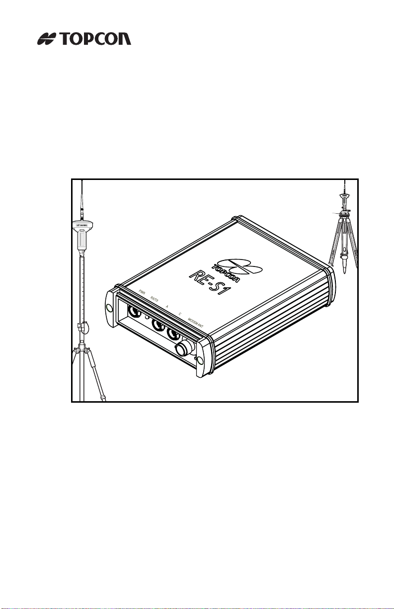
The RE-S1 is a 1W radio extension system using 915+ spread
spectrum technology. The RE-S1 can be used to enhance the
following survey-related systems:
• As a stand-alone repeater to increase the range between a Base
and Rover in spread spectrum systems, such as with the GR-3 or
HiPer Lite+ GPS systems.
• As a transmit/receive external 915+ radio for any Base system,
such as with the GB or Legacy series GPS receiver.
Obstructions—such as buildings, terrain, trees, etc—greatly affect the
usability and range of a spread spectrum system. The RE-S1 provides
radio repeater capabilites and increase the operational range and
effectivity of the system in unfavorable environments.
The RE-S1 simply extends the operational range of
NOTE
a spread spectrum system. It does not increase
range beyond the system’s OAF limitations.
P/N 7010-0780
Figure 1-1. RE-S1
1
Introduction
Getting Acquainted
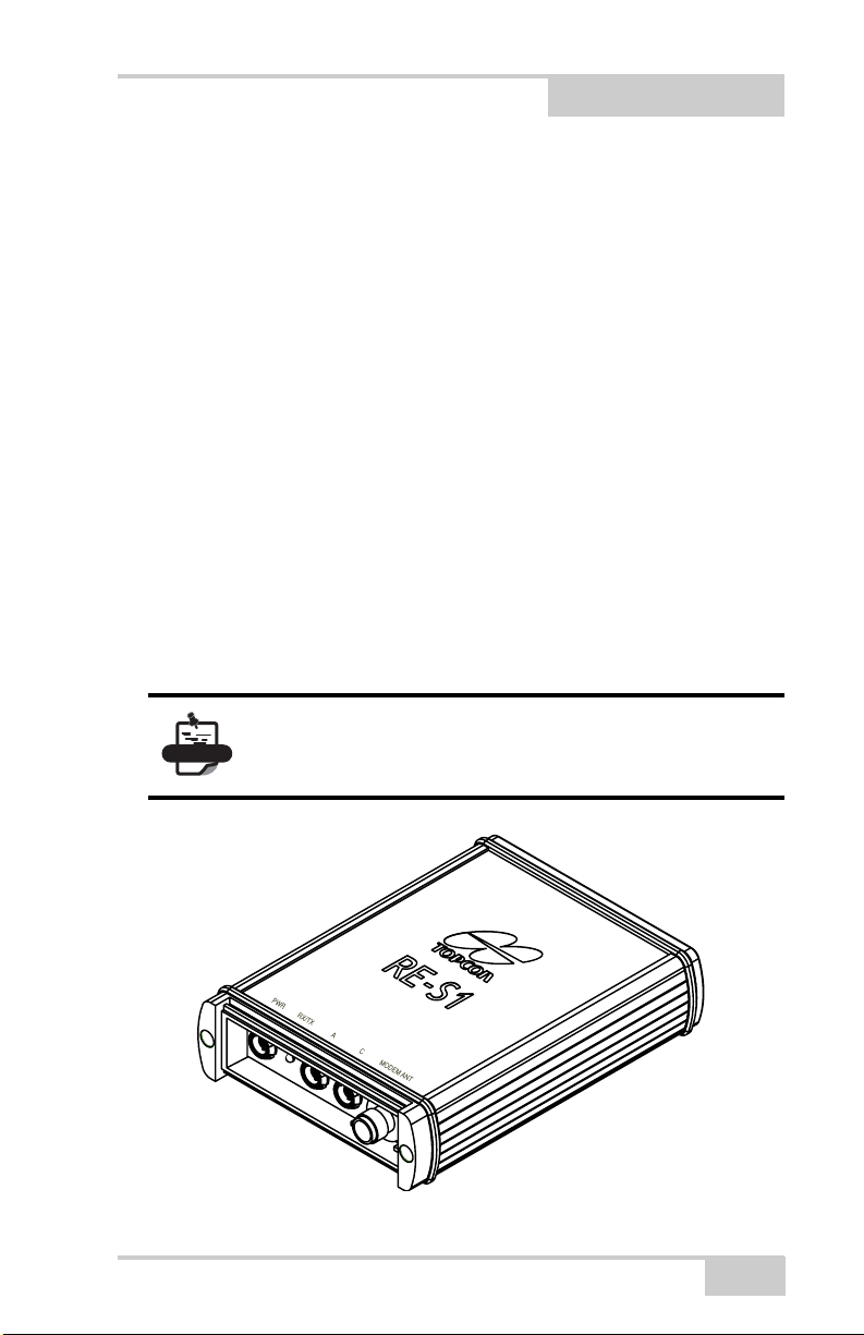
The RE-S1 is a transmit/receive/repeat 915+ spread spectrum radio
modem. The RE-S1 is compatible with existing Topcon spread
spectrum radio systems (some older HiPer models may need a radio
modem upgrade), as well as Topcon base stations. Simple features
allow the RE-S1 to be easily adaptable to any situation, and make it
easy to use.
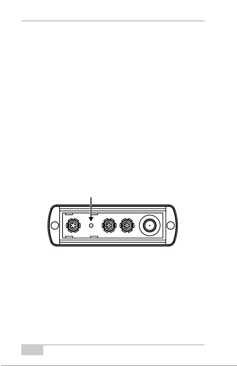
RX/TX LED
The RX/TX LED provides the following indications for the modem:
• Green flashes – modem is in receive mode and is searching for
radio link.
• Green solid – radio link established.
• Green solid with Red flash – modem is receiving.
• Red solid – modem is in transmit mode.
• Red flashes – improper configuration.
RX/TX LED
Figure 1-2. RE-S1 Receive/Transmit LED
LED notes: The RX/TX LED will be solid green with a red flash
when the Base receiver is within radio range of the repeater system.
The red flash indicates the following:
• A data packet has been received from the Base.
• A data packet has been transmitted from the repeater system.
If the RX/TX LED flashes green for an extended period of time,
check the following:
• The repeater’s distance from the Base.
2
RE-S1 Operator’s Manual
Getting Acquainted
• The channel of the RE-S1, Base, and Rover.
• The protocol of the RE-S1, Base, and Rover (FH915 Plus).
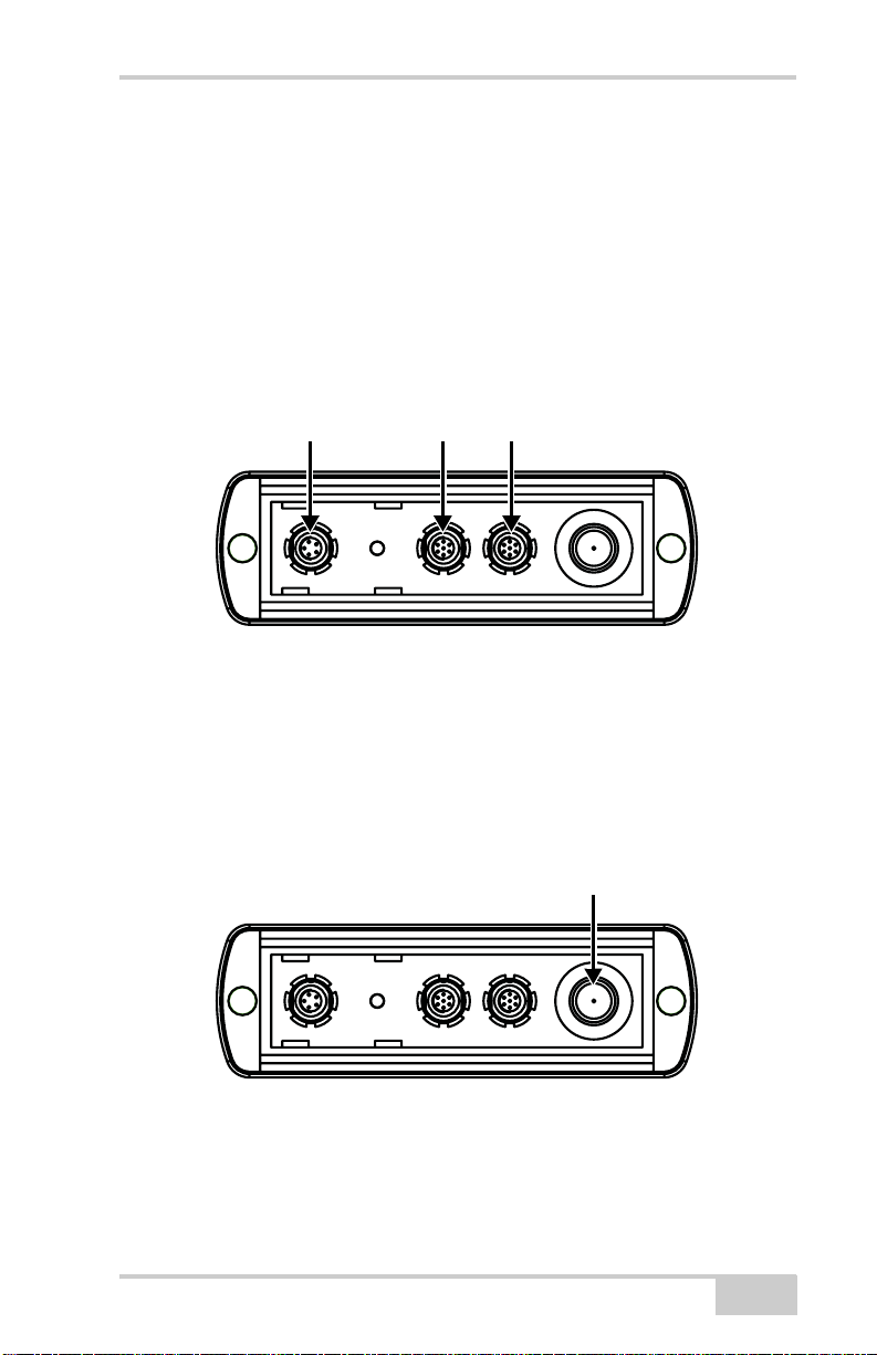
Data and Power Ports
The RE-S1 has the following ports:
• Power – used to connect the repeater an an external power source.
• Serial Ports A and C – used for communication between the
repeater and an external device (computer or controller).
Power Port Port A PortC
Figure 1-3. RE-S1 Ports
Radio Modem Antenna Port and Antenna
A spread spectrum reverse TNC radio antenna is required to receive/
transmit a radio signal. The antenna connectes to the antenna port on
the end of the RE-S1.
Radio Modem Antenna Port
Figure 1-4. RE-S1 Radio Antenna Port
P/N 7010-0780
3
Introduction
The spread spectrum modem antenna is a reverse polarity TNC RF
connection (p/n 30-030012-01).
SS Antenna
Figure 1-5. Modem Antenna
Standard Kit Cables and Power Supply
The standard RE-S1 package includes communication and power
cables for configuring the repeater and providing a power source to
the repeater. Table 1-1 lists the cables included in the package.
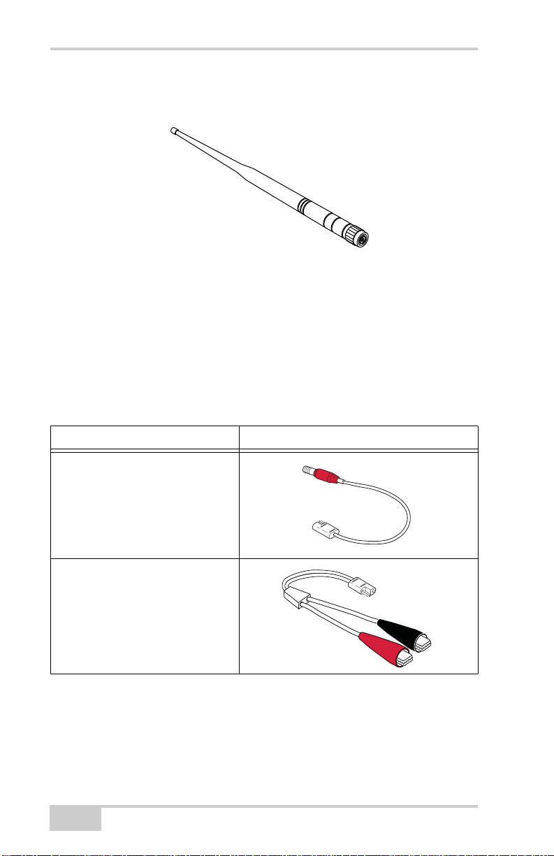
Table 1-1. RE-S1 Standard Package Cables
Cable Description Cable Illustration
Power/charging cable
Connects the repeater and the
power supply unit via SAE
connectors for battery charging.
Body of connector is red.
p/n 14-008016-03
Alligator clips-to-SAE cable
Connects the repeater to a mobile
external power source.
p/n 14-008025-01
4
RE-S1 Operator’s Manual
 Loading...