

Page 1
USER MANUAL
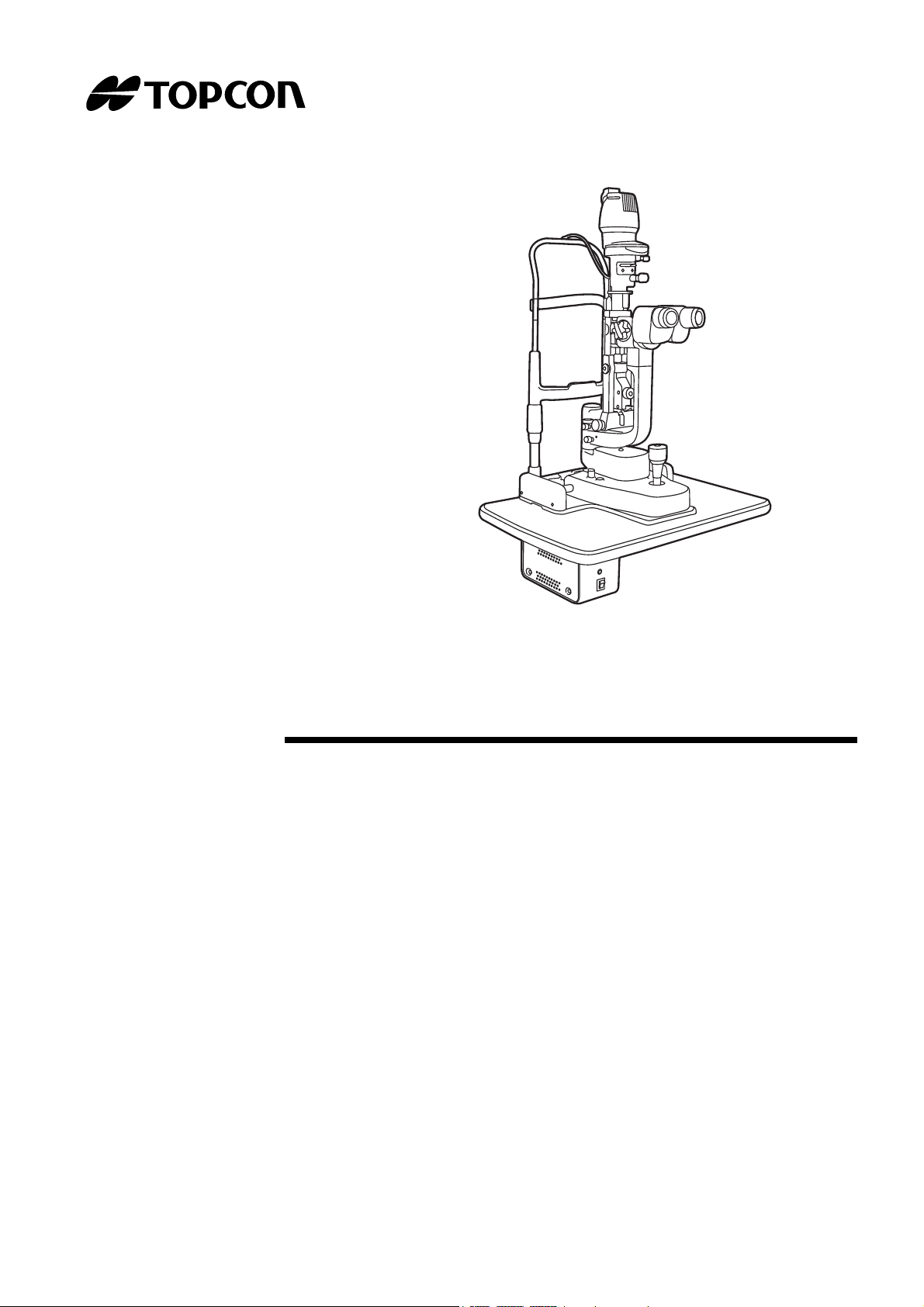
SLIT LAMP
SL-D701
Page 2

Page 3

INTRODUCTION
CAUTION : Federal law restricts this device to sale by or on the order of a Physician or
Practitioner(CFR 801.109(b)(1)).
Thank you for purchasing the SLIT LAMP SL-D701.
INTENDED USE / INDICATIONS FOR USE
The Slit Lamp SL-D701 is an AC-powered slitlamp biomicroscope intended for use in eye examination of the anterior eye segment, from the cornea epithelium to the posterior capsule. It is used to
aid in the diagnosis of diseases or trauma which affect the structural properties of the anterior eye
segment.
FEATURES
This instrument has the following features:
• Various accessories to extend the system
• Ergonomic cable layout
• Clear fluorescent cornea observation and photography of cornea
• Clear eyeground observation and photography by color conversion filter
PURPOSE OF THIS MANUAL
To get the best usage from the instrument, please read "DISPLAYS FOR SAFE USE" and "GENERAL SAFETY INFORMATION".
Keep this Manual with the instrument for future reference.
1
Page 4

2
1. No part of this manual may be copied or reprinted, in whole or in part, without prior written
permission.
2. The contents of this manual are subject to change without prior notice and without legal
obligation.
3. The contents of this manual are correct to the best of our knowledge. Please inform us of
any ambiguous or erroneous descriptions, missing information, etc.
4. Original Instructions
This instruction manual was originally written in English.
©2014 TOPCON CORPORATION
ALL RIGHTS RESERVED
Page 5

CONTENTS
INTRODUCTION ......................................................................................................................... 1
GENERAL SAFETY INFORMATION .................................................................................... 5
HOW TO USE THIS MANUAL ................................................................................................ 7
GENERAL MAINTENANCE INFORMATION ...................................................................... 7
DISCLAIMERS ............................................................................................................................ 7
DISPLAYS AND SYMBOLS FOR SAFE USE .................................................................... 8
POSITIONS OF WARNING AND CAUTION INDICATIONS .......................................... 9
SYSTEM DIAGRAM .......................................................................................................................... 10
COMPONENT NAMES .................................................................................................................. 10
COMPOSITION OF PARTS THAT COME IN CONTACT WITH THE PATIENT ........................... 10
STANDARD ACCESSORIES ......................................................................................................... 11
COMPONENTS .................................................................................................................................. 12
COMPONENTS .............................................................................................................................. 12
ASSEMBLY PROCEDURE ............................................................................................................. 14
SECURING THE INSTRUMENT TYPE TABLE TOP .................................................................... 14
SECURING THE UNIT TYPE TABLE TOP .................................................................................... 14
SECURING THE PATIENT GRIP PG-1(OPTIONAL ACCESSORY) ............................................. 15
SECURING THE CHINREST BASE PLATE .................................................................................. 15
SECURING THE BASE UNIT AND RAIL COVER ......................................................................... 15
SECURING THE BINOCULAR TUBES ......................................................................................... 16
SECURING THE ILLUMINATION UNIT ......................................................................................... 16
REMOVING THE ILLUMINATION UNIT PAD ................................................................................ 17
CONNECTING AND SECURING OF CABLES ............................................................................. 17
FITTING THE CHINREST TISSUE ................................................................................................ 18
FITTING THE CAP ......................................................................................................................... 18
SECURING THE TONOMETER MOUNT SO-TM1 (OPTIONAL ACCESSORY) .......................... 19
COUNTER BALANCING THE VERTICAL MOVEMENT ............................................................... 20
PREPARATIONS ............................................................................................................................... 22
POWERING ON ............................................................................................................................. 22
HOW TO RECOVER FROM THE POWER SAVING STATE ........................................................ 22
ADJUSTING THE DIOPTER AND PUPILLARY DISTANCE (PD) ................................................. 22
OPERATION PROCEDURE ........................................................................................................... 24
FIXING THE PATIENT'S FACE AND FIXATION ........................................................................... 24
OPERATING THE MICROSCOPE UNIT ....................................................................................... 25
OPERATING THE BASE AND FOCUSING ................................................................................... 26
OPERATING THE ILLUMINATION UNIT ...................................................................................... 27
ENDING PROCEDURE ................................................................................................................. 32
MAINTENANCE AND CHECKUPS .............................................................................................. 33
MAINTAINING THE PRECISION ................................................................................................... 33
PERIODIC MAINTENANCE ...........................................................................................................33
DAILY CARE .................................................................................................................................. 34
PLACING AN ORDER FOR CONSUMABLES .............................................................................. 34
USER MAINTENANCE ITEMS ...................................................................................................... 34
RESTOCKING CHINREST TISSUE .............................................................................................. 34
CLEANING ..................................................................................................................................... 35
CLEANING/DISINFECTING PATIENT-CONTACTING PARTS .................................................... 35
3
Page 6

CLEANING LENSES AND MIRRORS ........................................................................................... 35
CLEANING THE SLIDING PLATE, RAIL AND WHEEL SHAFT .................................................... 35
TROUBLESHOOTING ................................................................................................................... 36
TROUBLESHOOTING GUIDE ....................................................................................................... 36
SPECIFICATIONS AND PERFORMANCE .................................................................................... 37
GENERAL INFORMATION ON USAGE AND MAINTENANCE ........................................... 39
INTENDED PATIENT POPULATION ............................................................................................. 39
INTENDED USER PROFILE ..........................................................................................................39
ENVIRONMENTAL CONDITIONS FOR USE ................................................................................ 39
STORAGE, USAGE PERIOD ........................................................................................................ 39
ENVIRONMENTAL CONDITIONS FOR PACKAGING IN STORAGE ........................................... 40
ENVIRONMENTAL CONDITIONS FOR PACKAGING IN TRANSPORTAION ............................. 40
ELECTRIC RATING ....................................................................................................................... 40
DIMENSIONS AND WEIGHT ......................................................................................................... 40
SYSTEM CLASSIFICATION ..........................................................................................................41
OPERATION PRINCIPLES ............................................................................................................ 41
CHECKPOINTS FOR MAINTENANCE .......................................................................................... 41
DISPOSAL ..................................................................................................................................... 42
PATIENT’S ENVIRONMENT ......................................................................................................... 43
REQUIREMENTS FOR THE EXTERNAL DEVICE ....................................................................... 43
ELECTROMAGNETIC COMPATIBILITY ....................................................................................... 44
OPTICAL RADIATION HAZARD .................................................................................................... 48
TYPE OF PLUG ............................................................................................................................. 49
OPTIONAL ACCESSORIES ........................................................................................................... 50
SYSTEM CONFIGURATION ......................................................................................................... 50
DIGITAL CAMERA UNIT DC-4 ...................................................................................................... 51
BEAM SPLITTER ........................................................................................................................... 51
TV RELAY LENS ............................................................................................................................ 51
TV RELAY LENS TL-54/55 ............................................................................................................ 52
TV ATTACHMENT TL-56 ............................................................................................................... 52
TV ATTACHMENT TL-57 ............................................................................................................... 52
BACKGROUND ILLUMINATION BG-5 .......................................................................................... 53
OBSERVATION TUBE ................................................................................................................... 53
YELLOW FILTER UNIT .................................................................................................................. 53
IRIS DIAPHRAGM SO-DF01 .........................................................................................................53
12.5X EYEPIECE ........................................................................................................................... 53
20X EYEPIECE .............................................................................................................................. 53
TONOMETER MOUNT SO-TM1 .................................................................................................... 54
HRUBY LENS ................................................................................................................................ 54
PARALLEL BINOCULAR TUBE PB-2 ............................................................................................ 54
AUXILIARY SPRING SO-AS 1,2,3 ................................................................................................. 54
PATIENT HANDLE PG-1 ............................................................................................................... 54
4
Page 7
GENERAL SAFETY INFORMATION
CONTRAINDICATIONS
This instrument must not be used for the following patients:
• Patients who are hypersensitive to light
• Patients who recently underwent photodynamic therapy (PDT)
• Patients taking medication that causes photosensitivity.
WARNINGS
Ensuring the Safety of Patients and Operators
Use this instrument carefully on the following patients.
• Patients who have epidemic corneitis, conjunctivitis or any other infectious disease
• Patients who are taking medications that cause light hypersensitivity.
To avoid injury to the patient’s eye and nose, pay particular attention while operating the instrument
body. (The patient may be injured.)
The Topcon SL-D701 is a medical device. The software and hardware has been designed in accordance with U.S., European and other international medical device design and manufacturing standards. Unauthorized modification of the Topcon SL-D701 software or hardware, or any addition or
deletion of any application in any way can jeopardize the safety of operators and patients, the performance of the instrument, and the integrity of patient data.
Because prolonged intense light exposure can damage the retina, the use of the device for ocular
examination should not be unnecessarily prolonged, and the brightness setting should not exceed
what is needed to provide clear visualization of the target structures.
The retinal exposure dose for a photochemical hazard is a product of the radiance and the exposure
time. If the value of radiance were reduced in half, twice the time would be needed to reach the maximum exposure limit.
While no acute optical radiation hazards have been identified for direct or indirect ophthalmoscopes, it
is recommended that the intensity of light directed into the patient's eye be limited to the minimum level
which is necessary for diagnosis. Infants, aphakes and persons with diseased eyes will be at greater
risk. The risk may also be increased if the person being examined has had any exposure to the same
instrument or any other ophthalmic instrument using a visible light source during the previous 24 hours.
This will apply particularly if the eye has been exposed to retinal photography.
Equipment is not suitable for use in the presence of a Flammable Anesthetic Mixture with Air, Oxygen,
or Nitrous Oxide.
The Topcon SL-D701 has no special protection against harmful ingress of water or other liquids (classified IPX0). To avoid damage to the instrument and cause a safety hazard, the cleaning solutions,
including water, should not be directly applied to the device. Using a dampened cloth (without dripping), is a good method to clean the exterior surface of the enclosure.
Handling the cord on this product or cords associated with accessories sold with this product, will expose
you to lead, a chemical known to the State of California to cause birth detects or other reproductive harm.
Wash hands after handling.
5
Page 8
Preventing Electric Shock and Fire.
To avoid fire in the event of an instrument malfunction, immediately turn OFF the power switch ( ) and
disconnect the power cord from the instrument if you see smoke coming from the instrument, etc.
Don't install the instrument where it is difficult to disconnect the power cord from the instrument. Ask
your dealer for service.
CAUTIONS
Ensuring the Safety of Patients and Operators
Be careful not to let the patient touch this instrument. The patient's hand may be pinched by a movable
part.
To avoid burns caused by heat, do not replace the lamp with a new one immediately after it goes off.
To avoid injury to the patient's head, incline the illumination unit slowly while holding the base unit.
When operating the base unit, please note the following:
•Beware of catching fingers in the moving parts.
•Avoid hitting the patient's eyes or nose.
Preventing Electric Shock and Burn
To avoid injury or fire caused by electric shock, turn off the power switch and unplug the power cord
when not in use.
To avoid injury caused by electric shock, turn off the power switch when replacing the lamp.
Electromagnetic Compatibility (EMC)
This instrument has been tested (with 100/120/230V) and found to
2007as class B(classified according to CISPR11).
This instrument radiates radio frequency energy within standard and may affect other devices in the
vicinity.
If you have discovered that turning on/off the instrument affects other devices, we recommend you
change its position, keep a proper distance from other devices, or plug it into a different outlet.
Please consult your authorized dealer if you have any additional questions.
comply with IEC60601-1-2 Ed.3.0:
6
Page 9

HOW TO USE THIS MANUAL
• Read the instructions on pages 1 to 9 before using the machine.
• If you would like an overview of the system, begin by reading "OPERATION PROCEDURE" (page
24).
GENERAL MAINTENANCE INFORMATION
USER MAINTENANCE
To maintain the safety and performance of the instrument, unless done by an authorized service engineer, never attempt to do maintenance of items other than those specified here in.
For details about maintenance, read the description of this manual.
DISCLAIMERS
•TOPCON is not responsible for damage due to fire, earthquakes, actions or inactions of third
persons or other accidents, or damage due to negligence and misuse by the user and any use
under unusual conditions.
•TOPCON is not responsible for damage derived from inability to properly use this equipment,
such as loss of business profits and suspension of business.
•TOPCON is not responsible for damage caused by operations other than those described in this
user manual.
•The device does not provide a diagnose of any condition or lack thereof or any recommendation
for appropriate treatment. The relevant healthcare provider is fully responsible for all diagnose
and treatment decisions and recommendations.
7
Page 10
DISPLAYS AND SYMBOLS FOR SAFE USE
To encourage safe and proper use and to prevent injury to the operator and others or potential damage to
property, important messages are put on the instrument body and inserted in the instruction manual.
We suggest that everyone understand the meaning of the following displays, icons and text before reading the "GENERAL SAFETY INFORMATION" and observe all listed instructions.
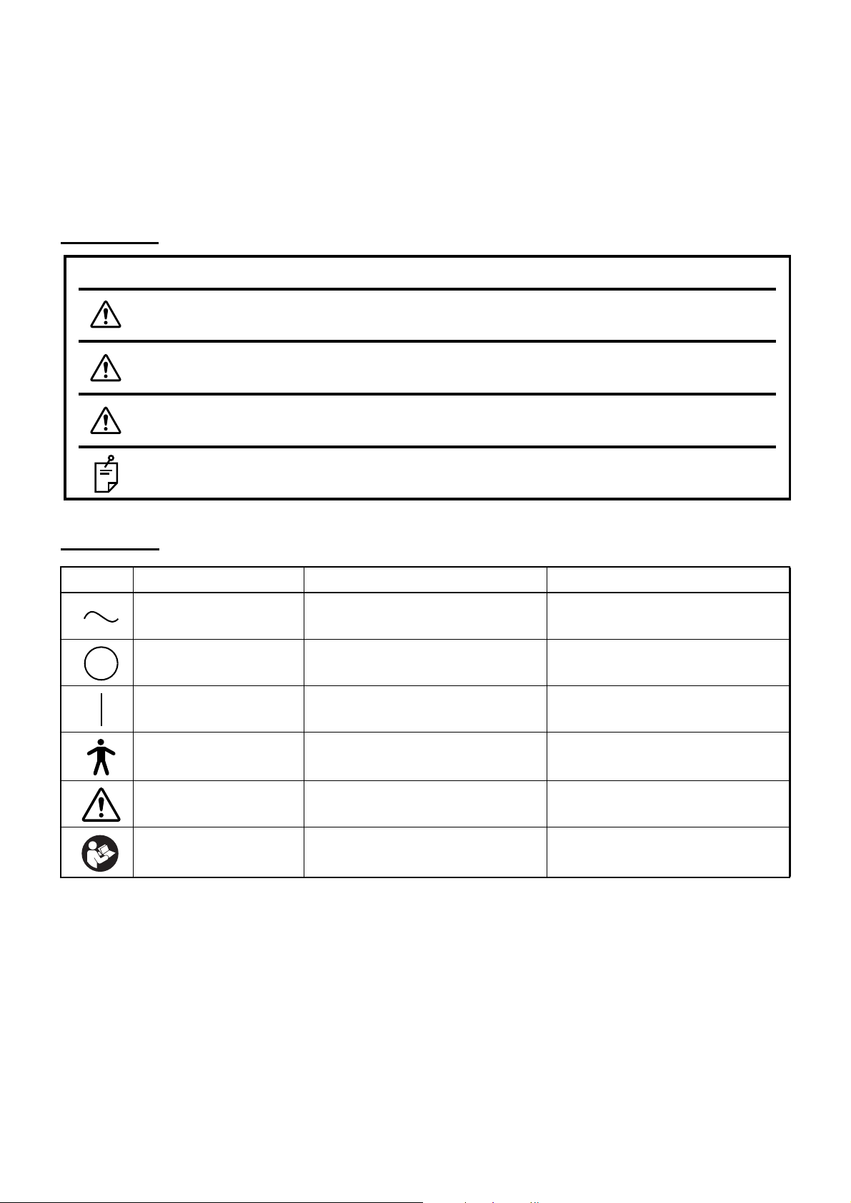
DISPLAYS
Display Meaning
Situations in which the device should not be used because the
CONTRAINDICATIONS
WARNINGS
CAUTIONS
NOTES
risk of use clearly outweighs any possible benefit.
Incorrect handling by ignoring this display may lead to a risk of
death or serious injury.
Incorrect handling by ignoring this display may lead to
personal injury or physical damage.
Useful functions to know. Paying attention to these will
prevent the noted problems.
SYMBOLS
Symbol IEC/ISO Publication Description Description (French)
IEC 60417-5032 Alternating Current Courant alternatif
IEC 60417-5008
IEC 60417-5007
IEC 60878-02-02 Type B applied part Partie appliquée du Type B
ISO 7010-W001 General warning sign
ISO 7010-M002
Off (power: disconnection from
the main power supply)
On (power: connection to the
main power supply)
Refer to instruction manual/
booklet
Éteint (courant: coupure avec le
secteur)
Allumé (courant: raccordement
sur le secteur)
Symbole d'avertissement
général
Voir le manuel/la brochure
8
Page 11
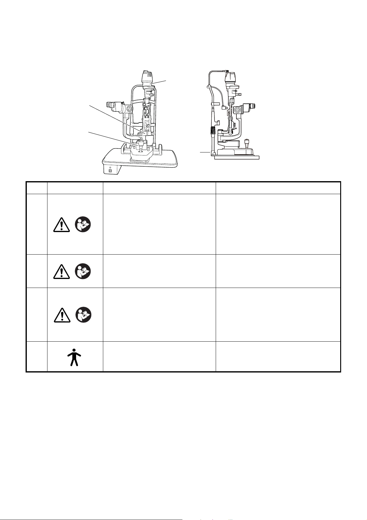
POSITIONS OF WARNING AND CAUTION INDICATIONS
2
1
3
4
To ensure safety, warning labels are provided on the instrument body.
Use the instrument following these warning instructions. If any of the following labels are missing, contact your dealer or TOPCON (see the back cover).
No. Label Meaning Signification
CAUTION
・To prevent electric shocks, switch off
the power supply and remove the
1
power cable before replacing the lamp.
・Do not replace the lamp immediately
after switching it off: the high temperatures could cause burns.
• Afin d’éviter les chocs électriques, coupez l’alimentation électrique et débranchez le câble d’alimentation avant de
remplacer la lampe.
• Ne pas remplacer la lampe immédiatement après l’avoir éteinte: la température
élevée peut provoquer des brûlures.
CAUTION
2
3
4
To avoid injury to the patient’s head,
incline the illumination unit slowly while
holding the base unit.
When operating the base unit, please
note the following:
・Beware of catching fingers in the
moving parts.
・Avoid hitting the patient’s eyes or
nose.
Degree of protection against electric
shock
: TYPE B APPLIED PART
Afin d’éviter de blesser le patient à la tête,
inclinez lentement l’élément lumineux tout
en maintenant la base de l’appareil.
Lorsque vous maniez la base de l’appareil,
veuillez noter les points suivants:
• Faites attention à ne pas vous coincer les
doigts dans les parties en mouvement.
• Évitez de heurter les yeux ou le nez du
patient.
Degré de protection contre les chocs électriques
: TYPE B PARTIE D'APPLICATION
PRÉCAUTION
PRÉCAUTION
PRÉCAUTION
9
Page 12
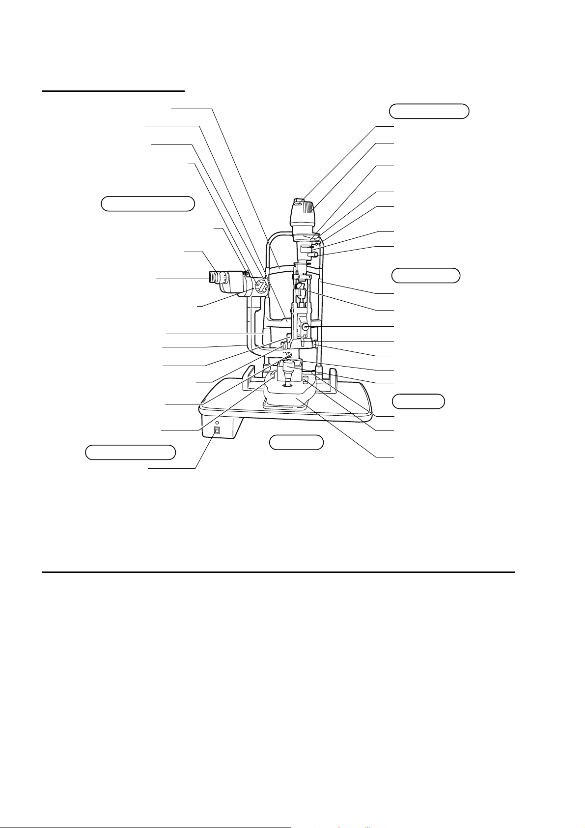
SYSTEM DIAGRAM
Plug
Lamp house cover
Aperture/slit length
display window
Color conversion filter
selector lever
Filter selector lever
Aperture/slit-length
selector knob
Canthus marker
Mirror
Centering knob
Inclination lever
Slit adjustment knob
Photo switch
Control lever
Base locking knob
Brightness adjustment
knob
Base
Forehead rest *4
Chinrest *4
Objective lens
Magnification selector
handle
Barrier filter selector lever *2
Diopter adjusting ring
12.5× eyepiece
Magnification index mark
Chinrest adjuster
Microscope arm
Power switch
Illumination Unit
Table *3
Power Supply
Microscope Unit
Base Unit
Chinrest Unit
Exciter filter *1
Illumination arm locking
knob
Microscope arm
locking knob
Illumination arm
Base relay cable
COMPONENT NAMES
*1,2 A model without exciter filter for slit lamp/barrier filter for slit lamp is also available.
*3 A model without table unit is also available.
*4 Contacting part (class B)
COMPOSITION OF PARTS THAT COME IN CONTACT WITH THE PATIENT
Forehead rest: Polyamide resin
Chinrest : Polyamide resin
10
SYSTEM DIAGRAM
Page 13
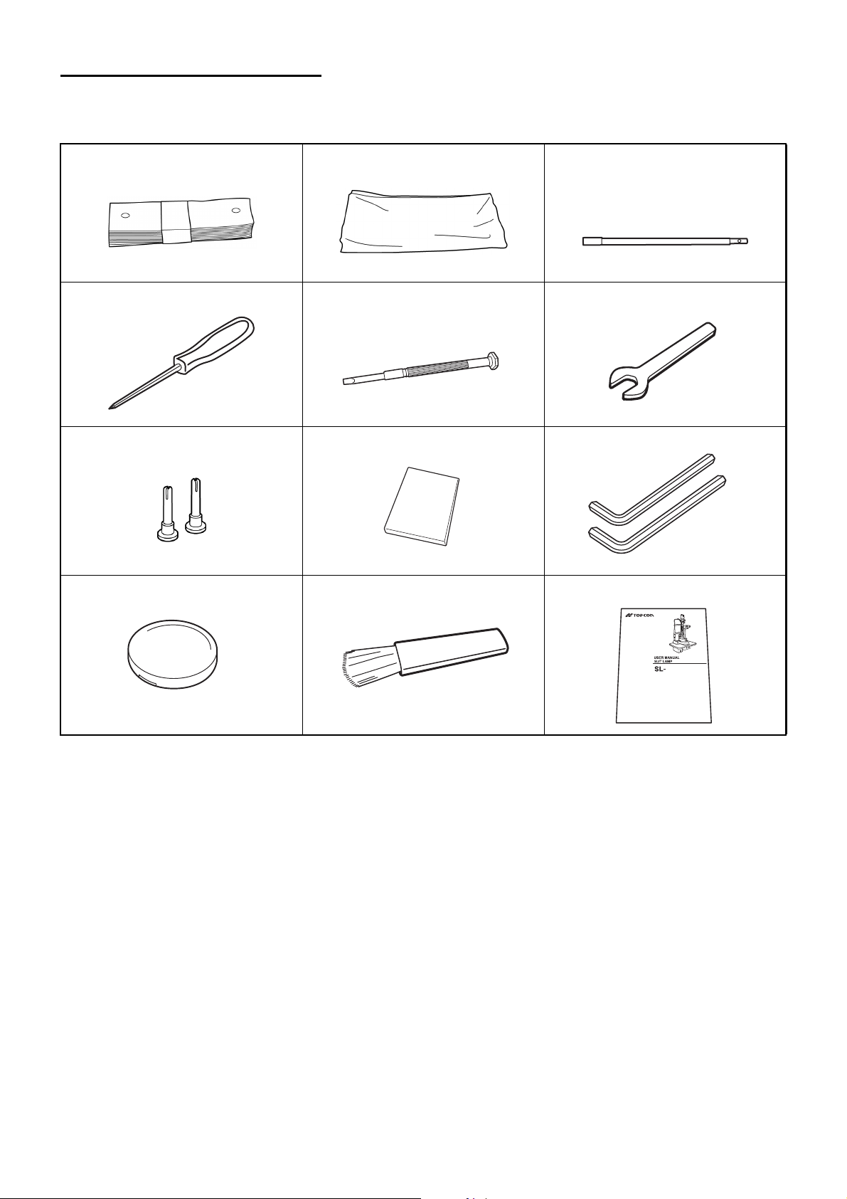
STANDARD ACCESSORIES
Make sure that all the following standard accessories are included.
Figures in parentheses are the quantities.
Chinrest tissue (1) Dust cover (1) Test rod (1)
(This is not always included with
the standard specifications.)
Crosshead screwdriver (1) Screwdriver (1) Spanner (1)
Spare chinrest tissue pin (2) Square mirror (1) Hexagon wrench (2)
Cap (1) Cleaning brush (1) User manual (1)
For optional accessories, see “Optional Accessories” on page 50.
D701
11
SYSTEM DIAGRAM
Page 14
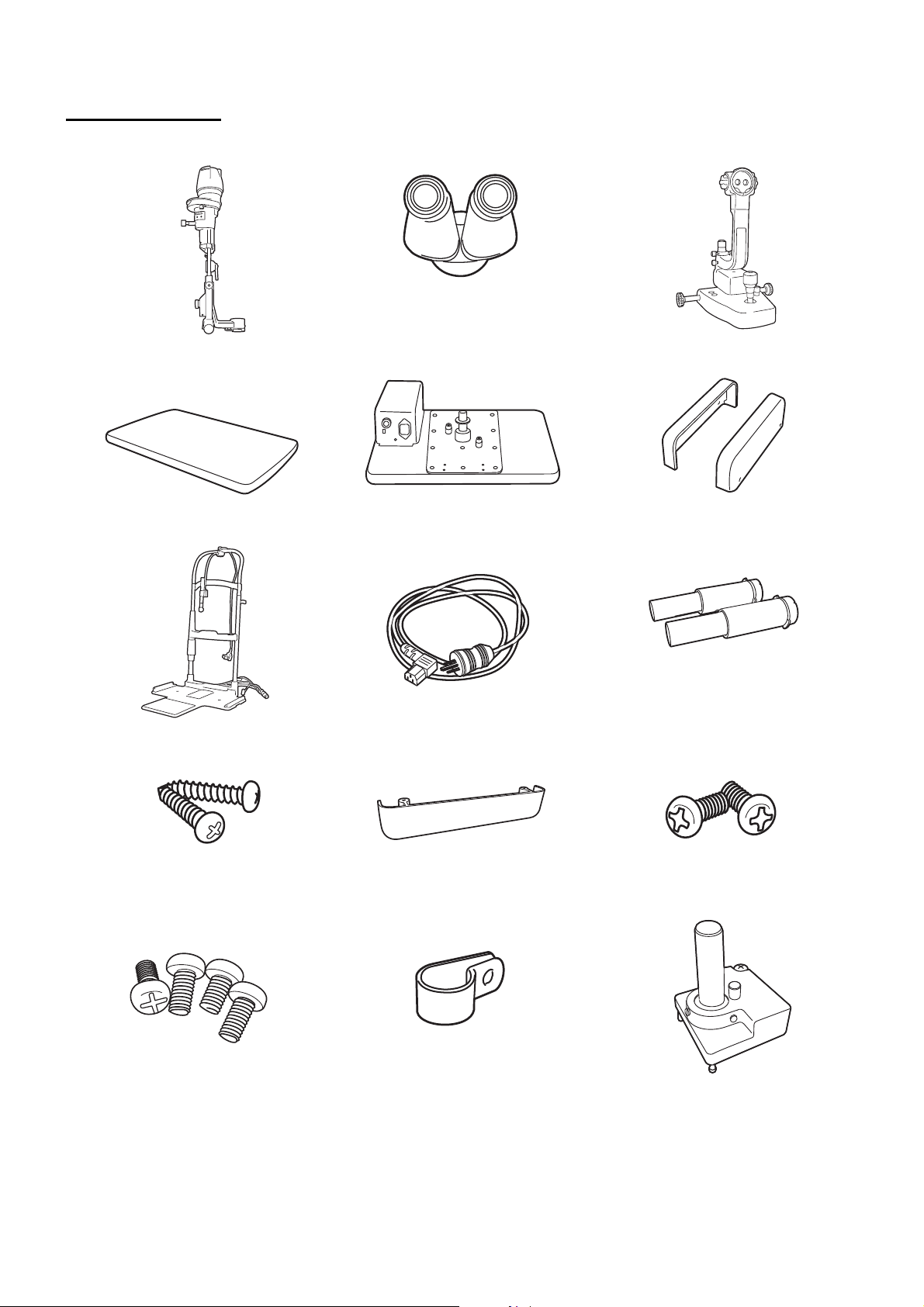
COMPONENTS
COMPONENTS
(1) Illumination unit (2) Binocular tubes (3) Base unit
(4) Instrument type table top
(w/power supply)
(6) Chinrest unit (7) Power cable (8) Auxiliary spring
(9) Chinrest fixing screw (10) Cable cover
(4)’ Unit type table top (5) Rail cover
(11) Cable cover fixing screw
* This component is unavailable
in some regions.
(12) Rail cover fixing screw (13) Cable clip (14) Tonometer maunt SO-TM1
12
COMPONENTS
Page 15

Article name Qty Article name Qty
(1) Illumination unit 1 (8) Auxiliary spring 2
(2) Binocular tubes 1 (9) Chinrest fixing screw 2
(3) Base unit 1 (10) Cable cover 1
(4) Instrument type table top
(w/power supply)*
or (4)’ Unit type table top* 1 (12) Rail cover fixing screw 4
(5) Rail cover 2 (13) Cable clip 3
(6) Chinrest unit* 1 (14) Tonometer maunt SO-TM1* 1
(7) Power cable 1
* (4) or (4)’ table top is not included, depending on the specifications.
* (6) Depending on chinrest and (14) Tonometer mount might not be included.
1 (11) Cable cover fixing screw 2
13
COMPONENTS
Page 16
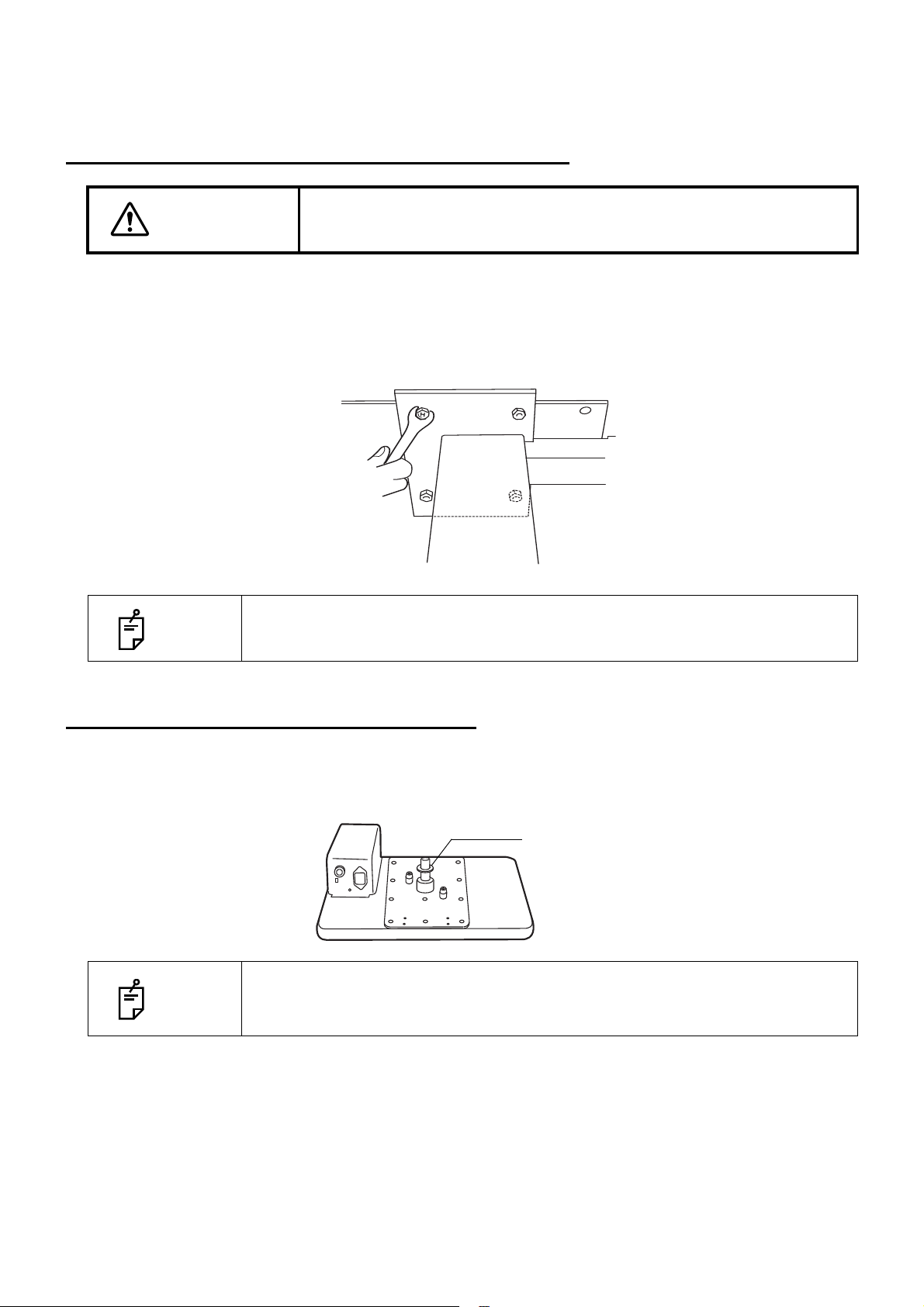
ASSEMBLY PROCEDURE
Washer
SECURING THE INSTRUMENT TYPE TABLE TOP
CAUTION
FITTING TO AUTOMATIC INSTRUMENT TABLE AIT-15/AIT-16
To prevent falling during use and movement, secure each unit.
1 Place the tabletop on the instrument table, and secure it with the 4 bolts attached to the instru-
ment table. To reverse the direction of the instrument table, remove the power supply from the
bottom of the table top and secure it on the opposite side.
NOTE
Connect the power cable to the table outlet and power supply of the instrument table.
Place the excess cable inside the cover, and attach the cover.
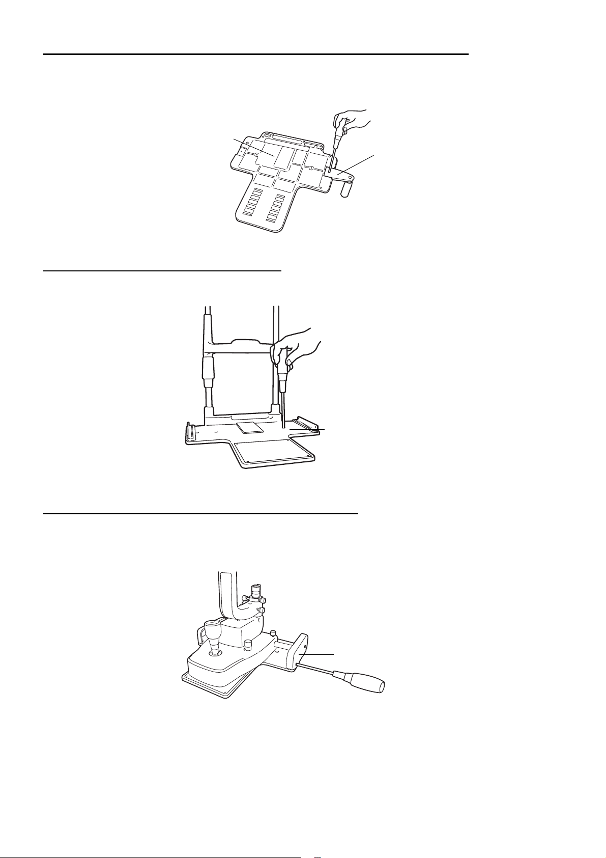
SECURING THE UNIT TYPE TABLE TOP
1 Remove the plastic washer from the unit type table top, which is taped to the shaft assembly.
2 Insert the plastic washer, together with the shaft, into the cavity for the ophthalmic unit arm.
In the unit type table top, the power supply is fitted to attach the ophthalmic unit on the
NOTE
right hand side. When attaching the ophthalmic unit on the left-hand side, remove the
power supply and reattach it to the right hand side (with 4 screws).
14
ASSEMBLY PROCEDURE
Page 17
SECURING THE PATIENT GRIP PG-1(OPTIONAL ACCESSORY)
Patient grip
Chinrest base
Chinrest base plate
Rail cover
1 Align the patient grip with a groove on the rear of the chinrest base.
2 Fix the patient grip with screws.
SECURING the Chinrest Base Plate
1 Secure the chinrest base plate to the unit type table top with 2 screws (9).
SECURING THE BASE UNIT AND RAIL COVER
1 Align the wheel of the base unit with the rail of the chinrest base plate.
2 Insert the connection cable into the LAN output terminal of the instrument.
15
ASSEMBLY PROCEDURE
Page 18
SECURING THE BINOCULAR TUBES
Screw
Microscope unit
30° - 60°
Indices
Indices
1 Align the pin of the microscope unit with the groove on the binocular tubes, and fit the screw with
a hexagon wrench.
In the model without excitor/barrier filter, fit binocular tube with the fixing screw.
NOTES
Make sure you do not touch the lens surfaces.
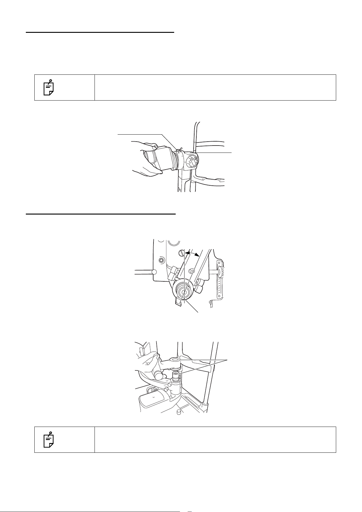
SECURING THE ILLUMINATION UNIT
Loosen the microscope arm locking-knob of the base unit, manually turn the shaft and tilt the guide rodshaft index 30-60°, then refasten the microscope-arm locking-knob.
2 Loosen the fixing screw on the outside of the fitting cavity of the illumination unit with a screw-
driver. Align indices and slowly lower the illumination unit onto the shaft of the base unit.
NOTES
While assembling the illumination unit, take care not to get your fingers caught.
16
ASSEMBLY PROCEDURE
Page 19

3 Firmly tighten the fixing screw with a screwdriver.
Protection pad (for transportation)
Plug
Illumination cable
Power cable
REMOVING THE ILLUMINATION UNIT PAD
1 Remove the rubber band and slowly withdraw the protection pad from the slit operation mecha-
nism of the illumination unit.
CONNECTING AND SECURING OF CABLES
1 Remove the tape from the lamp house cover of the illumination unit. Plug the cable from the
upper part of the chinrest into the illumination unit.
2 Connect the cable from the lower part of the chinrest unit and the power cable to the power sup-
ply.
17
ASSEMBLY PROCEDURE
Page 20

3 Pass the 8 pin connector from the metal plug connected to the power supply through the hole of
the chinrest and connect to the base unit.
4 Fit the cable cover with 2 screws (11).
5 Pull the base unit toward the side of the operator, then lock.
Attach the cables to the back of the table with the cable clip (13).
6 Move the base unit and illumination unit, and make sure there is enough cable to allow free
movement of the base unit in all directions.
FITTING THE CHINREST TISSUE
1 Remove the chinrest tissue pins.
2 Take approximately one-fifth of the pad of chinrest tissues and secure this at each end with the
pins.
FITTING THE CAP
1 Fit the cap to the shaft aligning the guide rod with the groove in the cap.
18
ASSEMBLY PROCEDURE
Page 21

SECURING THE TONOMETER MOUNT SO-TM1 (OPTIONAL ACCESSORY)
Screw
Locating Pin
The holes
Screw
Fixing knob
Depending on specification, SO-TM1 may be included in standard accessories.
1 Align the locating pin of SO-TM1 into the holes of the microscope, and fasten the screw.
2 Remove the fixing knob of the microscope, and secure the eyepieceunit, etc with the packaged
screw.
3 Applanation tonometer R900 type, Photokeratoscope attachment, etc could be mounted on SO-
TM1.
19
ASSEMBLY PROCEDURE
Page 22

COUNTER BALANCING THE VERTICAL MOVEMENT
When accessories, including the TV relay lens, are fitted to the main body, the vertical counter-balance movement may need to be adjusted. To correct this, auxiliary springs must be fitted.
Major Combinations of Accessories and Necessary Auxiliary Springs
Auxiliary Spring type
Accessories
TV relay lens TL-55 + SONY DXC-33 (DXC-390) –––
Beam splitter + Observation tube
Each auxiliary spring consists of 2 identical springs.
Do not use different springs in a set.
Tonometer is
not fitted
Standard
auxiliary
spring
Tonometer is
fitted
Standard
auxiliary
spring
Auxiliary
spring
SO-AS1
20
ASSEMBLY PROCEDURE
Page 23

COUNTER-BALANCE PROCEDURE
Cover
Auxiliary spring port
1 Turn the control lever clockwise and raise the base to the top position, remove the center screw
and take off the cover.
2 Insert the auxiliary spring unit vertically into the auxiliary spring port, with the flange face turned
upwards. (Make sure that the spring is inserted into the groove in the bottom of the port.
3 Open the auxiliary spring unit with the auxiliary spring port, and lightly push the spring till it stops.
(A large screwdriver, a flat sheet metal tool, a coin, etc. can be used to this end.)
4 With the auxiliary spring unit lightly touching the stopper, turn about 90° (in either direction), then
release. The auxiliary spring locks into the positioning groove and assembly is complete. (To
remove the auxiliary spring, lightly press it down to the stopper, rotate it 90° and remove from the
port.)
21
ASSEMBLY PROCEDURE
Page 24

PREPARATIONS
Tes t r od
Magnification selector handle
Slit adjustment knob
Aperture/slit-length selector knob
POWERING ON
To avoid fire and electric shock in case of leakage, be sure to use a
WARNING
1 Connect the power cable.
2 Turn ON the POWER switch.
HOW TO RECOVER FROM THE POWER SAVING STATE
Slit lamp is into the power saving state when approximately 30 minutes have passed since the slit lamp
was last used, and the slit illumination light becomes darker. The pilot lamp is blinking in orange during
the power saving mode.
1 Press the photo switch or swing the base widely from side to side.
2 Check that the illumination light is lighted by rotating the brightness adjustment knob.
grounded outlet. Do not connect to outlets that are not grounded.
ADJUSTING THE DIOPTER AND PUPILLARY DISTANCE (PD)
• To ensure sharp observation of slit images, always carry out the diopter and
NOTE
In case that no test rod is provided, set the diopter scale to your diopter by turning the diopter adjustment ring.
PD adjustments.
• The illumination light brightly shines for a moment immediately after powering
on.
1 Insert the test rod into the rotation shaft cavity, and set the black face square with the micro-
scope.
2 Set the eyepiece with scale to the non-dominant eye side.
3 Turn ON the POWER switch, and place the brightness adjustment knob in an intermediate posi-
tion.
22
PREPARATIONS
Page 25

4 Adjust the illumination to φ10mm by adjusting the slit adjustment knob and aperture/slit-length
Prism box
Diopter adjusting ring
Diopter scale
selector knob.
5 Rotate the magnification selector handle to the minimum magnification (6x).
6 Turn the diopter adjusting ring of the eyepiece with scale ( ) fully counter-clockwise.
7 Turn the diopter adjusting ring clockwise and stop when both the scale ( ) and test rod can be
clearly seen.
8 Read the value on the diopter scale of the stop position. The value shows the diopter (D).
9 Set the diopter scale of the other eyepiece to the read value.
10 Set the eyepiece with scale ( ) to the dominant eye side, and adjust the diopter scale of the
dominant eye as in steps 5 and 6.
11 After adjusting the diopter, turn the slit adjustment knob until the slit width is about 1mm, then
check if the slit image projected on the test rod can be clearly seen with both right and left eyes.
12 Holding the prism box, look through the eyepiece with both eyes, and adjust the pupillary dis-
tance so that the image projected on the test rod can be seen without diplopia (double vision),
and appears to be three dimensional.
23
PREPARATIONS
Page 26

OPERATION PROCEDURE
Forehead rest
Canthus marker
Chinrest
Chinrest adjuster
(A) Fixation target with
diopter adjustment
(B) Luminous fixation target
Diopter adjusting
ring
Fixation target unit
Fixation target
lever
FIXING THE PATIENT'S FACE AND FIXATION
The model without a fixation target is also available.
1 Place the patient's chin on the chinrest with his forehead against the forehead rest.
2 By rotating the chinrest adjuster, align the patient's eye with the canthus marker on the chinrest
frame.
3 Ask the patient to look at the fixation target with the eye that is not being examined.To change the
patient's fixation point, hold the fixation target at the end opposite to the target and adjust accordingly.
• When using the fixation target with diopter adjustment (A), slide the diopter
adjustment knob so that the patient can see the following target ( ).
NOTE
• The ring target can be adjusted within a range of -15D to +10D.
• The luminous fixation target is used for myopia of -15D or more.
• When replacing targets, remove the target by pulling gently whilst supporting
the opposite end.
24
OPERATION PROCEDURE
Page 27

OPERATING THE MICROSCOPE UNIT
Magnification selector
handle
Magnification index mark
Turn the magnification selector to set a magnification value against the magnification index mark.
For the overall magnification in conjunction with magnification marks of the
NOTE
magnification selector handle, see page 37.
25
OPERATION PROCEDURE
Page 28

OPERATING THE BASE AND FOCUSING
Base locking knob
Base
Control lever
• To avoid injury to the eye and nose whilst moving the base unit, make
sure that you have a clear view of the slit lamp and the patient's face.
CAUTION
To prevent dropping the base locking knob from the base, do not loosen the
NOTE
knob too much
•
For the safety of the operator and the patient, do not place fingers between
moving parts.
1 For major horizontal movements, hold the control lever in the upright position and move the
entire base.
2 For fine adjustments, move the control lever in the required direction.
3 The base can be raised by turning the control lever clockwise, and lowered by turning the control
lever counter-clockwise.
4 To fix the base, fasten the base locking knob.
NOTE
• Rough focusing is carried out with major movements, following step 1-3.
• Fine focusing is done with the microscope, following steps 2 and 3.
26
OPERATION PROCEDURE
Page 29

OPERATING THE ILLUMINATION UNIT
Brightness adjustment
knob
Slit-width control knob
• To avoid injury to the patient’s head, incline the illumination unit holding the base unit.
CAUTION
• Adjust the slit width according to the results of the investigation.
NOTE
ADJUSTING THE BRIGHTNESS
Turn the brightness adjustment knob.
The brightness of the illumination light can be adjusted to the preferred illumination setting.
• The slit-width scale should be used as a guideline.
• When using the square mirror, incline the illumination unit at least 10º.
• To avoid causing discomfort to the patient or any damage to the
patient's eye, keep the illumination at its minimum during adjustment.
ADJUSTING THE SLIT WIDTH
Turn the slit-width control knob.
The slit width can be changed gradually between 0 and 14mm (14mm=circle).
27
OPERATION PROCEDURE
Page 30

CHANGING THE APERTURE/SLIT LENGTH
Aperture/slit-length
display window
Aperture/slit-length
control knob
Aperture/slit-length
control knob
Slit-angle scale
Centering knob
Turn the aperture/slit-length control knob.
When the slit is fully opened, 6 types of spot illumination (φ14, φ10, φ5, φ2, φ1, φ0.2) are available.
The slit width can be changed gradually from 1mm to 14mm.
NOTE
The spot illumination size and slit length are displayed on the aperture/slitlength display window.
TURNING THE SLIT
Horizontally rotate the aperture/slit-length control knob.
This directly changes the slit image from vertical to horizontal. In this mode, the slit angle can be
read off the angle scale.
SWINGING THE SLIT SIDEWAYS
Loosen the centering knob and swing the illumination unit right and left.
This provides indirect illumination displacing the slit light from the microscope center.
By fastening the centering knob, the slit light returns to the center of the vision field.
NOTE
28
OPERATION PROCEDURE
This function is used for scanning observation and observation with indirect illumination.
Page 31

INCLINED ILLUMINATION
Inclination lever
Square mirrorBattledore mirror
Press to unlock the inclination lever and pull.
The illumination unit is inclined for inclined illumination up to 20° in 5° steps.
NOTE
This function is used for observing a horizontal cross section, and for corner
angle and fundus observation.
REFLECTION MIRROR
For this instrument, a battledore mirror and a square mirror are available. For normal observation,
the battledore mirror is used.
However, if the arm angle scale, which represents the angle formed by the illumination arm and
microscope arm, reads approx. 3° to 10° and the observation light flux is disturbed by the battledore
mirror, then the square mirror should be used.
The square mirror is to be used when the arm angle is opened to more than 10°
.
NOTE
The square mirror is standard accessory.
29
OPERATION PROCEDURE
Page 32

REPLACING REFLECTION MIRRORS
Square mirror
Battledore mirror
Green-colored
No filter ND filter
Blue filter
Red-free filter
Blue-colored
With Ex /Ba filter
No filter ND filter
no filter ( )
Red-free filter
Without Ex /Ba filter
Green-colored
Aperture/slit length
display window
Filter selector lever
Aperture/slit length
control knob
Replace mirrors as follows, taking care not to touch the mirror and lens surfaces:
•Open the microscope arm and illumination arm 30° or more.
•Incline the illumination unit 10° or more.
•Pull out the battledore mirror, holding the slender part on both sides. To reinsert the battledore mirror, hold the slender part on both sides and insert.
•Insert the square mirror from the side recessed on the back.
•To pull out the square mirror, which has no handle, push the square mirror up as illustrated below.
NOTE
ess on page 35 "Cleaning Lenses and Mirrors".
CHANGING FILTERS
If you touch the mirror or lens surface, please clean this according to the proc-
Move the filter selector lever right and left to select the required filter from the 4 types.
B
BLUE FILTER
For the SL-D701 without exciter/barrier type, rotate the Aperture/Slit-Length knob counter-clockwise
until the blue circle appears in the aperture display window. The blue filter will be ready to use.
30
OPERATION PROCEDURE
Page 33

AMBER FILTER
Amber filter selector
lever
OFF
ON
Aperture/slit-length
control knob
Aperture/slit-length
display window
Barrier filter selector lever
The amber filter is used to facilitate fundus observation.
The filter is inserted or removed by the amber filter selector lever.
FLUORESCENCE OBSERVATION
(EXCITER FILTER FOR SLIT LAMP/BARRIER FILTER FOR SLIT LAMP)
Fluorescence observation can be carried out using the exciter filter for slit lamp and barrier filter for
slit lamp.
1 Turn the aperture/slit-length display window anti-clockwise until the blue circle appears, then
insert the exciter filter for slit lamp into the illumination path.
2 Turn the barrier filter selector lever to the right and insert the barrier filter for slit lamp.
NOTE
This setting is availabel for users who have SL-D701 “with EX / Ba filter” type.
OPERATION PROCEDURE
31
Page 34

DIFFUSION LENS
Diffusion lens
When in use, the diffusion lens is set vertically in front of the reflection mirror.
When not in use, remove the lens from the light path.
NOTE
The diffusion lens is used for observing the entire object with a low magnification.
ENDING PROCEDURE
Turn OFF the Power switch.
NOTE
The illumination light brightly shines for a moment when turning the power off.
32
OPERATION PROCEDURE
Page 35

MAINTENANCE AND CHECKUPS
MAINTAINING THE PRECISION
ADJUSTING THE SLIT WIDTH CONTROL KNOB TORQUE
•If the slit width narrows by itself due to a decrease in slit width control knob torque, adjust the
torque as follows.
1 Using the attached hexagon wrench, loosen the slit width control knob.
2 Press the slit-width control knob on the left-hand side, and turn the right-hand side clockwise.
3 Fasten the slit width control knob on the right-hand side with the hexagon wrench.
ADJUSTING THE INCLINATION TORQUE
•If the inclination torque of the illumination unit is too low, fasten the arm inclination by tightening the
screws clockwise on both sides of the arm.
PERIODIC MAINTENANCE
Before using, confirm the following:
•Adjust the diopter and eye width following "ADJUSTING THE DIOPTER AND PUPILLARY DISTANCE (PD)" on page 22 and turn the slit adjustment knob and make the slit width about 1mm:
The slit image projected on the test rod is seen clearly.
•Move the base forward-backward and right-left: The base moves smoothly.
•Component parts, including the eyepiece unit, are fitted in place.
•The chinrest base is firmly fitted to the table.
•Cables and plugs are firmly connected.
33
MAINTENANCE AND CHECKUPS
Page 36

DAILY CARE
•This instrument may be affected adversely by dust. Apply the dust cover when not using.
PLACING AN ORDER FOR CONSUMABLES
•When ordering consumable items, contact your dealer or TOPCON (see the back cover).
Specify the article name, product code and quantity.
Article name Product code
Chinrest tissue 403104082
USER MAINTENANCE ITEMS
Item Inspection time Contents
Inspection Before using • Adjusting the diopter and pupillary distance
• Focus of slit image
• The base unit must move smoothly.
• The components must be fitted in place correctly.
• The chinrest unit must be fitted to the table unit correctly.
• The cables and plugs must be connected correctly.
• The objective lens, eyepiece and mirror must not be stained or
damaged.
Cleaning When the part is
stained
Adjustment As required • Slit width control knob torque
Supply As required • Chinrest tissue
• Objective lens
• Eyepiece
• Mirror
• Sliding plate, rail and wheel shaft unit
• Forehead rest and chinrest unit
• Inclination torque of illumination unit
RESTOCKING CHINREST TISSUE
When the chinrest tissue supply is depleted, pull out the chinrest tissue pins and replace tissue.
34
MAINTENANCE AND CHECKUPS
Page 37

CLEANING
Rail
Wheel shaft
Sliding plate
Control lever
• Before carrying out daily care, remove the power cable (to avoid electric shocks) and wait until the lamp house has cooled (to avoid burns).
CAUTION
• To prevent the chinrest, forehead rest and other plastic parts from discolora-
NOTE
• Wipe parts with a cloth moistened with a tepid solution of neutral kitchen detergent.
• Do not touch parts inside the lamp house cover during operation and
immediately after switching off the power supply: this could cause
burns.
tion and deterioration, do not use volatile solvents for cleaning, including benzine, thinner, ether, gasoline, etc.
CLEANING/DISINFECTING PATIENT-CONTACTING PARTS
Clean the forehead rest, the chinrest and the patient grip (if a pair of patient grip is used) with an
alcohol wipe before and after each patient.
CLEANING LENSES AND MIRRORS
REMOVING STAINS
NOTE
To prevent damaging lens surfaces, do not hold gauze with tweezers.
1 Prepare a solution of ethyl alcohol 20% and ether 80%.
2 Remove dust from lens and mirror surfaces with the cleaning brush, or a blower.
3 Using clean gauze or lint-free tissue, lightly clean with a rotating movement from the center of the
lens/mirror outwards.
4 If the stain remains, repeat this 2 to 3 times.
5 If stains are persistent, call your dealer or TOPCON (see the back cover).
CLEANING THE SLIDING PLATE, RAIL AND WHEEL SHAFT
NOTE
When stained, the movement of the sliding plate and rail of the tabletop and the wheel
shaft of the base becomes less smooth. Clean them with a dry cloth.
1 Move the base right and left and wipe the wheel shaft clean with a dry cloth.
2 Hold up the control lever and clean the sliding plate with a dry cloth.
35
MAINTENANCE AND CHECKUPS
Page 38

TROUBLESHOOTING
TROUBLESHOOTING GUIDE
To avoid electric shocks, do not attempt overhauling, rebuilding or
CAUTION
If you suspect a problem, check the possible cause by means of the check list below.
If the check list below does not solve the problem, or if the problem is not included in the list, contact
your dealer or TOPCON (see the back cover).
Problem Possible cause Check Page
Cable connection is
disconnected
Base relay cable is switched off. Connect the cable. 17
Plug of lamp house cover is switched off Insert plug. 17
Illumination lamp
does not work
Illumination field is
not uniform/is
shady/is dark
Slit width narrows by
itself
Slit lamp is into a power saving state.
POWER switch is OFF Turn ON POWER switch. 22
Brightness adjustment knob is the mini-
mum
Illumination lamp is broken Replace it with a new illumination lamp
Slit width is the minimum Rotate the slit adjustment knob
Filter selector lever is out of position Click filter selector lever. 30
Slit-adjustment knob torque has been
decreased
repairs. Ask your dealer for repair.
Check List
Check cable connection. 17
Recover from power saving state by
pressing the Photo switch or swinging
the base from side to side.
Turn up brightness adjustment knob. 27
Readjust slit-width control knob torque. 33
22
-
22
36
MAINTENANCE AND CHECKUPS
Page 39

SPECIFICATIONS AND PERFORMANCE
SPECIFICATIONS AND PERFORMANCE
Microscope unit
Type Galileo type
Magnification Drum, 5-step magnification
Magnification steps 6/10/16/25/40
6.37 (φ35.1mm)
9.94 (φ22.5mm)
Overall magnification (actual vision field)
Eyepiece lens
PD adjustment range
Barrier filter
Illumination unit
Illumination field
Aperture diameter φ14, 10, 5, 2, 1, 0.2mm
Slit direction Vertical to horizontal, can be altered gradually
Inclination
Filter
Illumination lamp 3A 10W LED
Base unit
Forward-backward movement length 90mm
Right-left movement length 100mm
Vertical movement length 30mm
Fine adjustment in all directions length 12mm
Chinrest unit
Adjustable range of the vertical direction 80mm
Fixation target*
1
15.87 (φ14.1mm)
25.37 (φ8.8mm)
39.62 (φ5.6mm)
Magnification: 12.5x
Diopter adjustment range: -5D to +5D
55 to 78mm
Available for use IN/OUT the sight (A model, with or without bar-
rier filter, is available. The model with barrier filter houses the
Illumination Unit with exciter filter.)
Slit width: 0 to14mm, can be altered gradually(14mm=circle)
Slit length: 1 to14mm, can be altered gradually(14mm=circle)
5°, 10°, 15,° 20° from below
Available for use side swing
Blue filter, red-free filter, ND filter (13% transmission), amber filter, UV cut filter (normal use), IR cut filter (normal use), exciter filter (A model, with or without exciter filter, is available. The model
with exciter filter houses the Microscope Unit with barrier filter.)
Fixation target with diopter adjustment
Light source for fixation target: LED
*1, A model without fixation target is also available.
• The specification and design of the product can be altered for improvements without prior notice.
MAINTENANCE AND CHECKUPS
37
Page 40

Agency Compliance
The SL-D701 is designed to comply with the following agency standards:
• IEC 60601-1: 2005
• AAMI/ANSI ES 60601-1: 2005/A1: 2012
• CAN/CSA C22.2 No.60601-1-08
• EN 60601-1: 2006/AC: 2010
• IEC 60601-1-2: 2007
• EN 60601-1-2: 2007/AC: 2010
• ISO 10939: 2007
• ISO 15004-1: 2006
• ISO 15004-2: 2007
• EC Medical Device Directive 93/42/EEC
NOTE
The illumination light is not to be turned off.
38
MAINTENANCE AND CHECKUPS
The following statement is the "Essential performance" provided for by IEC60601-1.
Page 41

GENERAL INFORMATION ON USAGE AND MAINTENANCE
INTENDED PATIENT POPULATION
The patient who undergoes an examination by this instrument must maintain concentration for a few
minutes and keep to the following instructions:
To fix the face to the chinrest, forehead rest.
To keep the eye open.
To understand and follow instructions when undergoing an examination.
INTENDED USER PROFILE
The SL-D701 SLIT LAMP is an electric instrument for medical use.
Use this instrument under a doctor's guidance.
ENVIRONMENTAL CONDITIONS FOR USE
Temperature : 10°C to 40°C
Humidity : 30% to 90% (without dew condensation)
Air pressure : 700hPa to 1060hPa
STORAGE, USAGE PERIOD
1. Environmental conditions (without package)
* Temperature : 10°C to 40°C
Humidity : 10% to 95% (without dew condensation)
Air pressure : 700hPa to 1060hPa
*THIS INSTRUMENT DOES NOT MEET THE TEMPERATURE REQUIREMENTS OF ISO 15004-1
FOR STORAGE. DO NOT STORE THIS INSTRUMENT IN CONDITIONS WHERE THE TEMPERATURE MAY RISE ABOVE 40°C OR FALL BELOW 10°C.
2. When storing the instrument, ensure that the following conditions are met:
(1) The instrument must not be splashed with water.
(2) Do not store the instrument in an environment where air pressure, temperature, humidity, venti-
lation, sunlight, dust, salty/sulfurous air, etc. could cause damage.
(3) Do not store or transport the instrument on a slanted or uneven surface or in an area where it is
subject to vibrations or instability.
(4) Do not store the instrument where chemicals are stored or gas is generated.
3. Normal life span of the instrument:
8 years from delivery providing regular maintenance is performed (according to the self-certification
[TOPCON data])
39
GENERAL INFORMATION ON USAGE AND MAINTENANCE
Page 42

ENVIRONMENTAL CONDITIONS FOR PACKAGING IN STORAGE
Temperature : -20°C to 50°C
Humidity : 10% to 95%
ENVIRONMENTAL CONDITIONS FOR PACKAGING IN TRANSPORTAION
Temperature : -40°C to 70°C
Humidity : 10% to 95%
ELECTRIC RATING
Source voltage : AC100 - 240V
Frequency : 50 - 60Hz
Power input : 110 VA
DIMENSIONS AND WEIGHT
Dimensions, Weight
Dimensions:
w/Table 550mm(W) x 420mm(D) x 752 to 782mm(H)
w/ Unit Table 440mm(W) x 397mm(D) x 752 to 782mm(H)
w/o Table 329mm(W) x 396mm(D) x 652 to 682mm(H)
w/o Table and Chinrest 329mm(W) x 331(304)mm(D) x 652 to 682mm(H)
Weight: w/Table 19kg
w/ Unit Table 18kg
w/o Table 13kg
w/o Table and Chinrest 11.5kg
Table size 550mm x 370mm
Unit Table size 440mm x 350mm
Height from the top to patient’s eye 375mm
40
GENERAL INFORMATION ON USAGE AND MAINTENANCE
Page 43

SYSTEM CLASSIFICATION
• Type of protection against electric shocks: Class Ι equipment
Class Ι equipment does not depend on basic insulation only for protection against electric shocks. It can
also be earthed; therefore, the metal parts with which one comes into contact do not become conductive if the basic insulation fails.
• Degree of protection against electric shocks: Type B applied part
Type B applied part is the applied part complying with the specified requirements of the Standard IEC
60601-1 to provide protection against electric shock, particularly regarding allowable LEAKAGE CURRENT.
• Degree of protection against harmful ingress of water: IPx0
SL-D701 has no protection against ingress of water. (The degree of protection against harmful ingress
of water defined in IEC 60529 is IPx0)
• Classification according to the methods of sterilization or disinfection recommended by the manufacture: not applicable.
SL-D701 has no part to be sterilized or be disinfected.
• Not AP or APG equipment
• Classification according to the degree of safety of application in the presence of a flammable anaesthetic mixture with air or with oxygen or nitrous oxide: Equipment not suitable for use in the presence of
a flammable anaesthetic mixture with air or with oxygen or nitrous oxide.
SL-D701 should be used in environments where no flammable anesthetics and/or flammable gases are
presents.
• Classification according to the mode of operation: Continuous operation.
Continuos operation is the operation under normal load for an unlimited period, without the specified
limits of temperature being exceeded.
OPERATION PRINCIPLES
Illuminates the observed part by the illumination light emitted from the illumination optical system and allows
enlargement observation by binocular stereoscopic microscope.
CHECKPOINTS FOR MAINTENANCE
1. Regularly maintain and check the instrument and its parts.
2. When using the instrument after a prolonged period of inactivity, confirm normal and safe operation
beforehand.
3. To take a good picture, be careful not to stain the objective lens with fingerprints or dust.
4. When this instrument is not in use, cap the objective lens and cover the instrument with the dust
cover.
5. When the objective lens is stained, clean it according to "Cleaning Lenses and Mirrors" in this manual.
41
GENERAL INFORMATION ON USAGE AND MAINTENANCE
Page 44

DISPOSAL
This symbol is applicable for EU member countries only.
To avoid potential damage to the environment and possibly human
health, this instrument should be disposed of (i) for EU member countries - in accordance with WEEE (Directive on Waste Electrical and
Electronic Equipment), or (ii) for all other countries, in accordance with
local disposal and recycling laws.
The base contains strong springs. Do not attempt to disassemble or
CAUTION
• When disposing of SL-D701 parts, follow the local regulations for disposal and recycling.
burn the base, as the springs could cause injury by shooting out of it.
NOTES
42
GENERAL INFORMATION ON USAGE AND MAINTENANCE
Page 45

PATIENT’S ENVIRONMENT
Do not use the power strip in the
patient's environment. Connect the
power supply of the device to the
commercial power supply.
Radius 1.5m
1.5m
2.5m
1.5m
Devices applicable to the
•Digital camera
patient’s environment
When the patient or inspector may touch the devices (including the connecting devices) or
when the patient or inspector may touch the person that comes into contact with the devices
(including the connecting devices), the patient's environment is shown below.
In the patient's environment, use the device conforming to IEC60601-1. If you are compelled to
use any device not conforming to IEC60601-1, use an insulation transformer or the common
protective earth system.
Requirements for the EXTERNAL DEVICE
The external device connected to the analog and digital interfaces must comply with the
respective IEC or ISO standards (e.g. IEC 60950-1 for data processing equipment and IEC
60601-1 for medical equipment).
Anybody connecting additional equipment to medical electrical equipment configures a medical
system and is therefore responsible that the system complies with the requirements for medial
electrical systems. Attention is drawn to the fact that local laws take priority over the above
mentioned requirements. If in doubt, contact your dealer or TOPCON (see the back cover).
43
GENERAL INFORMATION ON USAGE AND MAINTENANCE
Page 46

ELECTROMAGNETIC COMPATIBILITY
This product conforms to the EMC standard (IEC 60601-1-2 Ed.3: 2007).
a) MEDICAL ELECTRICAL EQUIPMENT needs special precautions regarding EMC and needs to be
installed and put into service according to the EMC information provided in the ACCOMPANYING
DOCUMENTS.
b) Portable and mobile RF communications equipment can affect MEDICAL ELECTRICAL EQUIPMENT.
c) The use of ACCESSORIES, transducers and cables other than those specified, with the exception of
transducers and cables sold by the manufacturer of the EQUIPMENT or SYSTEM as replacement
parts for internal components, may result in increased EMISSIONS or decreased IMMUNITY of the
EQUIPMENT or SYSTEM.
d) The EQUIPMENT or SYSTEM should not be used adjacent to or stacked with other equipment. If adja-
cent or stacked use is necessary, the EQUIPMENT or SYSTEM should be observed to verify normal
operation in the configuration in which it will be used.
e) The use of the ACCESSORY, transducer or cable with EQUIPMENT and SYSTEMS other than those
specified may result in increased EMISSION or decreased IMMUNITY of the EQUIPMENT or SYS-
TEM.
Item Article code
ACCESSORIES
BACKGROUND ILLUMINATION BG-5 44797 9025 - - CABLES
AC Power cord (for SLIT LAMP) 44804 7015 Not Used Not Used 1.5
ILLUMINATION cable 44701 4510 Used Used 0.6
Cable
shield
Ferrite
core
Length(m)
Guidance and manufacturer's declaration - electromagnetic emissions
The SL-D701 is intended for use in the electromagnetic environment specified below. The customer or
the user of the SL-D701 should assure that it is used in such an environment.
Emissions test Compliance Electromagnetic environment - guidance
RF emissions
CISPR 11
RF emissions
CISPR 11
Harmonic emissions
IEC61000-3-2
Voltage fluctuations/
flicker emissions
Group 1
Class B
Class A
Complies
The SL-D701 uses RF energy only for its internal function.
Therefore, its RF emissions are very low and are not likely
to cause any interference in nearby electronic equipment.
The SL-D701 is suitable for use in all establishments including domestic and those directly connected to the public lowvoltage power supply network that supplies buildings used
for domestic purposes.
IEC61000-3-3
44
GENERAL INFORMATION ON USAGE AND MAINTENANCE
Page 47

Guidance and manufacturer's declaration - electromagnetic immunity
The SL-D701 is intended for use in the electromagnetic environment specified below. The customer or
the user of the SL-D701 should assure that it is used in such an environment.
Immunity test
Electrostatic
discharge (ESD)
IEC 61000-4-2
Electrical fast
transient/burst
IEC 61000-4-4
Surge
IEC 61000-4-5
Voltage dips, short
interruptions and
Voltage variations
on power supply
input lines
IEC 61000-4-11
IEC 60601
test level
± 6 kV contact
± 8 kV air
± 2 kV for power
supply lines
± 1 kV for
input/output lines
± 1 kV
line(s) to line(s)
± 2 kV
line(s) to earth
<5% U
t
(>95% dip in Ut)
for 0.5 cycle
40% U
t
(60% dip in Ut)
for 5 cycles
70% U
t
(30% dip in Ut)
for 25 cycles
<5% U
t
(>95% dip in Ut)
for 5 sec
Compliance
level
± 6 kV contact
± 8 kV air
± 2 kV for power
supply lines
± 1 kV for
input/output lines
± 1 kV
line(s) to line(s)
± 2 kV
line(s) to earth
<5% U
t
(>95% dip in Ut)
for 0.5 cycle
40% U
t
(60% dip in Ut)
for 5 cycles
70% U
t
(30% dip in Ut)
for 25 cycles
<5% U
t
(>95% dip in Ut)
for 5 sec
Electromagnetic environment -
guidance
Floors should be wood, concrete or
ceramic tile. If floors are covered with
synthetic material, the relative humidity
should be at least 30%.
Main power quality should be that of a
typical commercial or hospital environment.
Main power quality should be that of a
typical commercial or hospital environment.
Main power quality should be that of a
typical commercial or hospital environment. If the user or the SL-D701
requires continued operation during
main power interruptions, it is recommended that the SL-D701 be powered
from an uninterruptible power supply or
battery.
Power frequency
(50/60 Hz)
magnetic field
IEC 61000-4-8
NOTE U
is the a.c. main voltage prior to application of the test level.
t
3 A/m 3 A/m
GENERAL INFORMATION ON USAGE AND MAINTENANCE
Power frequency magnetic fields
should be at levels characteristic of a
typical location in a typical commercial
or hospital environment.
45
Page 48

Guidance and manufacturer's declaration - electromagnetic immunity
PPP
The SL-D701 is intended for use in the electromagnetic environment specified below. The customer or
the user of the SL-D701 should assure that it is used in such an environment.
Immunity test IEC 60601
test level
Conducted RF
IEC 61000-4-6
Radiated RF
IEC 61000-4-3
3 Vrms
150kHz to 80MHz
3 V/m
80MHz to 2.5GHz
Compliance
level
3 V
3 V/m
Electromagnetic environment -
guidance
Portable and mobile RF communications
equipment should be used no closer to any
part of the SL-D701, including cables, than
the recommended separation distance calculated from the equation applicable to the frequency of the transmitter.
Recommended separation distance
d = 1.2
d = 1.2 80MHz to 800MHz
d = 2.3 800MHz to 2.5GHz
where P is the maximum output power rating
of the transmitter in watts (W) according to
the transmitter manufacturer and d is the rec-
ommended separation distance in meters
(m).
Field strengths from fixed RF transmitters, as
determined by an electromagnetic site sur-
a
vey,
should be less than the compliance
level in each frequency range.
Interference may occur in the vicinity of
equipment marked with the following symbol:
NOTE 1
NOTE 2
abField strengths from fixed transmitters, such as base stations for radio (cellular/cordless) telephones
and land mobile radios, amateur radio, AM and FM radio broadcast and TV broadcast cannot be predicted theoretically with accuracy. To assess the electromagnetic environment due to fixed RF transmitters, an electromagnetic site survey should be considered. If the measured field strength in the
location in which the SL-D701 is used exceeds the applicable RF compliance level above, the SLD701 should be observed to verify normal operation. If abnormal performance is observed, additional
measures may be necessary, such as reorienting or relocating the SL-D701.
At 80 MHz and 800 MHz, the higher frequency range applies.
These guidelines may not apply in all situations. Electromagnetic propagation is affected by
absorption and reflection from structures, objects and people.
b
Over the frequency range 150 kHz to 80 MHz, field strengths should be less than 3 V/m.
46
GENERAL INFORMATION ON USAGE AND MAINTENANCE
Page 49

Recommended separation distance between
PPP
portable and mobile RF communications equipment and the SL-D701
The SL-D701 is intended for use in an electromagnetic environment in which radiated RF disturbances
are controlled. The customer or the user of the SL-D701 can help prevent electromagnetic interference
by maintaining a minimum distance between portable and mobile RF communications equipment
(transmitters) and the SL-D701 as recommended below, according to the maximum output power of the
communications equipment.
Rated maximum output
power of transmitter
W
0.01 0.12 0.12 0.23
0.1 0.38 0.38 0.73
1 1.2 1.2 2.3
10 3.8 3.8 7.3
100 12 12 23
For transmitters rated at a maximum output power not listed above, the recommended separation distance d in meters (m) can be estimated using the equation applicable to the frequency of the transmitter, where P is the maximum output power rating of the transmitter in watts (W) according to the
transmitter manufacturer.
NOTE 1
NOTE 2
At 80 MHz and 800 MHz, the separation distance for the higher frequency range applies.
These guidelines may not apply in all situations. Electromagnetic propagation is affected
by absorption and reflection from structures, objects and people.
Separation distance according to frequency of transmitter
m
150kHz to 80MHz
d = 1.2
80MHz to 800MHz
d = 1.2
800MHz to 2.5GHz
d = 2.3
47
GENERAL INFORMATION ON USAGE AND MAINTENANCE
Page 50

OPTICAL RADIATION HAZARD
• The light radiated from the instrument is potentially hazardous. The
longer the exposure time is, the higher the risk of causing disorder to
CAUTION
RELATIVE SPECTRAL DISTRIBUTION OF ILLUMINATION LIGHT
㪈
㪇㪅㪐
㪇㪅㪏
㪇㪅㪎
㪇㪅㪍
㪇㪅㪌
㪇㪅㪋
㪇㪅㪊
㪩㪼㫃㪸㫋㫀㫍㪼㩷㫀㫅㫋㪼㫅㫊㫀㫋㫐
㪇㪅㪉
㪇㪅㪈
㪇
㪊㪇㪇 㪋㪇㪇 㪌㪇㪇 㪍㪇㪇 㪎㪇㪇 㪏㪇㪇 㪐㪇㪇
the eye is.
• When operating with the maximum intensity, the light radiation
reaches values exceeding the safety guideline in about 84sec.
㪣㪜㪛㩷㫀㫃㫃㫌㫄㫀㫅㪸㫋㫀㫆㫅㩷㫊㫇㪼㪺㫋㫉㪸㫃㩷㪻㫀㫊㫋㫉㫀㪹㫌㫋㫀㫆㫅
㪮㪸㫍㪼㫃㪼㫅㪾㫋㪿㩿㫅㫄㪀
㪙㪸㪺㫂㪾㫉㫆㫌㫅㪻㩷㫍㫀㫊㫀㪹㫃㪼㩷㫀㫃㫃㫌㫄㫀㫅㪸㫋㫀㫆㫅㩷㫊㫇㪼㪺㫋㫉㪸㫃㩷㪻㫀㫊㫋㫉㫀㪹㫌㫋㫀㫆㫅
㪈
㪇㪅㪐
㪇㪅㪏
㪇㪅㪎
㪇㪅㪍
㪇㪅㪌
㪇㪅㪋
㪇㪅㪊
㪩㪼㫃㪸㫋㫀㫍㪼㩷㫀㫅㫋㪼㫅㫊㫀㫋㫐
㪇㪅㪉
㪇㪅㪈
㪇
㪊㪇㪇 㪋㪇㪇 㪌㪇㪇 㪍㪇㪇 㪎㪇㪇 㪏㪇㪇 㪐㪇㪇
㪮㪸㫍㪼㫃㪼㫅㪾㫋㪿㩿㫅㫄㪀
Because prolonged intense light exposure can damage the retina, the use of the device for ocular examination
should not be unnecessarily prolonged, and the brightness setting should not exceed what is needed to provide
clear visualization of the target structures.
The retinal exposure dose for a photochemical hazard is a product of the radiance and the exposure time. If the
value of radiance were reduced in half, twice the time would be needed to reach the maximum exposure limit.
While no acute optical radiation hazards have been identified for slit lamps, it is recommended that the intensity
of light directed into the patient's eye be limited to the minimum level which is necessary for diagnosis. Infants,
aphakes and persons with diseased eyes will be at greater risk. The risk may also be increased if the person
being examined has had any exposure with the same instrument or any other ophthalmic instrument using a visible light source during the previous 24 hours. This will apply particularly if the eye has been exposed to retinal
photography.
48
GENERAL INFORMATION ON USAGE AND MAINTENANCE
Page 51

TYPE OF PLUG
Country Voltage/frequency Type of plug
Mexico 110V/50Hz Type C&E
Argentina 220V/60Hz Type A
Peru 220V/60Hz Type A
Venezuela 110V/50Hz Type C&E
Bolivia & Paraguay 220V/60Hz Type A (Most common)
Type H (Infrequently)
Chile 220V/60Hz Type A
Colombia 110V/50Hz Type C
Brazil 220V/60Hz
127V/60Hz
Ecuador 110V/50Hz Type C&E
USA 120V/60Hz Type A (Hospital Grade)
Canada 120V/60Hz Type A (Hospital Grade)
Type A
Type C
49
GENERAL INFORMATION ON USAGE AND MAINTENANCE
Page 52

OPTIONAL ACCESSORIES
TOPCON product
Products of other
System Chart
Background Illumination
BG-5
Hruby
Lens
AUXILIARY SPRING
SO-AS1, 2, 3
PATIENT HANDLE PG-1
Yellow Filter
Iris Diaphragm
SO-DF01
Tonometer Mount
SO-TM1
Applanation
Tonometer
Model R900
Beam
Splitter
TV Relay Lens
TL-54 (1/2C)
TV Relay Lens
TL-55 (1/3C)
TV ATT
TL-57
TV ATT
TL-56
Adapt Cover
SO-AC 6,7
Digital Camera Unit DC-4
Dedital Camera
1/2C Video
Camera
(Adapter Lens)
SONY
DXC-390/-C33
Panasonic
GP-KS162
1/2 TV Camera
Observation
Tube
TV Relay Lens
bayonet mount 1/2
TV
Relay Lens
Cmount 1/2
TV
Relay Lens
Cmount 1/3
Monitor TV
Video
Camera
Still Video
Recorder
Printer
Parallel
binoculer Tubes
PB-2
12.5X
Eyepiece
12.5X
Eyepiece
12.5X
Eyepiece
12.5X
Eyepiece
20X
Eyepiece
The one there is no click but
with measurement scale.
The one there is click, and
without scale.
The one there is click, and
with scale.
The one there is click, and
with measurement scale.
IMAGEnet
TOPCON SLIT LAMP SL-D701 provides the following optional accessories for imaging.
For inquiries, please call your dealer or TOPCON (see the back cover)
To prevent falling during use and movement, secure optional accesso-
CAUTIONS
•For details, please refer to the instruction manuals of each product.
SYSTEM CONFIGURATION
CAUTIONS
ries.
To avoid electric shock, do not touch the external connection terminal
and the patient at the same time.
50
OPTIONAL ACCESSORIES
Page 53

DIGITAL CAMERA UNIT DC-4
FEATURES
• Simple operation and high-quality digital image.
• Optimized functions for slit lamp photography.
• Compact body and internal cabling for a neat look.
• All DC-4 functions are software driven.
BEAM SPLITTER
FEATURES
• Used to attach the TV relay lens and observation tube.
• The TV relay lens and observation tube can be attached to either side.
• The beam splitter division ratio is TV 50% : operator 50%.
TV RELAY LENS
• Three types of TV relay lens are prepared for different TV camera types to be used (C mount 1/2 type,
C mount 1/3 type and bayonet mount 1/2 type).
FEATURES
• Used with the beam splitter.
• Can connect a TV camera to carry out monitor observation and
photographing of still images.
51
OPTIONAL ACCESSORIES
Page 54

TV RELAY LENS TL-54/55
• Two types of TV relay lenses differ according to the type of TV camera to be used.
For C mount 1/2 type TV camera: TL-54
For C mount 1/3 type TV camera: TL-55
FEATURES
• Incorporated with the beam splitter.
• Can connect a TV camera to carry out monitor observation and photographing of still images.
• The beam splitter IN/OUT can be selected.
• The beam splitter division ratio is TV 50%: operator 50%.
TV ATTACHMENT TL-56
FEATURES
• Used to connect a digital camera.
• Combined with beam splitter.
• The beam splitter division ratio is TV 50%: operator 50%.
TV ATTACHMENT TL-57
FEATURES
• Used to connect a digital camera.
• Combined with beam splitter.
• The beam splitter division ratio is TV 50%: operator 50%.
52
OPTIONAL ACCESSORIES
Page 55

BACKGROUND ILLUMINATION BG-5
FEATURES
• Used for background illumination.
• The light volume differs according to the illumination light volume of the slit lamp.
• Equipped with 3-step visible observation illumination function.
OBSERVATION TUBE
FEATURES
• Used in combination with a beam splitter.
• Used for observation together with the operator.
• Can be inclined to facilitate observation.
YELLOW FILTER UNIT
FEATURES
• Combines with the blue filter prepared in the main body for a
high-contrast fluorescence observation.
• Easy switching between filter insertion & removal.
IRIS DIAPHRAGM SO-DF01
FEATURES
• When taking picture, you can adjust the light intensity and the depth according to the
need.
12.5x Eyepiece
FEATURES
There are four types as below:
• One with internal measurement scale and no click stops.
• One without internal scale and click stops on each adjustment step.
• One with internal scale and click stops on each adjustment step.
• One with internal measurement scale and click stops on each adjustment step.
20X EYEPIECE
FEATURES
• Replaces the normal eyepiece for high magnification observation.
53
OPTIONAL ACCESSORIES
Page 56

TONOMETER MOUNT SO-TM1
FEATURES
• This is a mount used for attaching the Applanation Tonometer AT 900
model R (Haag Streit) to the SL-D701.
HRUBY LENS
FEATURES
Normally, observation is possible only up to the anterior vitreous body due to the
refractive power of the cornea and lens. With the Hruby lens, the posterior vitreous
body and the retina can be observed..
PARALLEL BINOCULAR TUBE PB-2
FEATURES
• Can observe a parallel view of the object.
AUXILIARY SPRING SO-AS 1,2,3
FEATURES
• Used to counter-balance vertical movement when
attaching accessories, such as a photography unit.
PATIENT HANDLE PG-1
FEATURES
• A grip for patient confort to hold during diagnosis and
photographing.
• Can be attached to the chinrest base.
54
OPTIONAL ACCESSORIES
Page 57

Please provide the following information when contacting us regarding questions
about this instrument:
• Model name: SL-D701
• Serial No.: This is printed on the rating nameplate on the right side of the
power supply unit.
• Period of use: Please inform us of the date of purchase.
• Defective condition: Please provide us with as much detail as possible on the
problem.
SLIT LAMP
SL-D701
USER MANUAL
The 2014 version
Date of issue: July 3, 2014
Published by TOPCON CORPORATION
75-1 Hasunuma-cho, Itabashi-ku, Tokyo, 174-8580 Japan.
Page 58

SLIT LAMP
0
SL-D701
Printed in Japan 1407-100TH
44701 95950
 Loading...