

Page 1
INSTRUCTION MANUAL
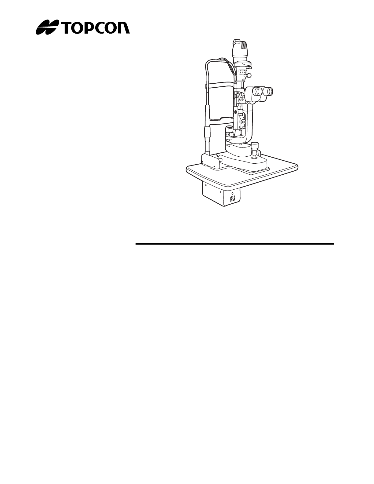
SLIT LAMP
SL-D7
SL-D8Z
Page 2

Page 3

1
INTRODUCTION
Thank you for purchasing the Slit Lamp SL-D7, SL-D8Z.
This slit lamp is used for the enlargement observation of eyeballs and the parts.
This instrument has the following features:
• Various accessories to extend the system
• Ergonomic cable layout
• Clear fluorescent cornea observation and photography of cornea
• Clear eyeground observation and photography by color conversion filter
This Instruction Manual covers an overview of the basic operation, troubleshooting, checking,
maintenance and cleaning of the Slit Lamp SL-D7, SL-D8Z.
To get the best usage from the instrument, please read “Displays for Safe Use” and “Safety Cautions”.
Keep this Instruction Manual with the instrument for future reference.
(Without package)
PRECAUTIONS
WORKING ENVIRONMENT
Temperature: 10°C-40°C
Humidity: 30-75% (no dewing)
Atmospheric Pressure: 700hPa-1,060hPa
STORAGE METHOD (without package)
1. Environmental Conditions
Temperature: 10°C-40°C
Humidity: 30-75% (no dewing)
Atmospheric Pressure:700hPa-1,060hPa
2. Place of Storage
(1) Protected from water splashes
(2) Protected from adverse effects caused by atmospheric pressure, temperature, mois-
ture, ventilation, sunlight, dust, salt content, sulfur, etc.
(3) Stable, without slopes, and protected from vibrations, shocks (including transporta-
tion), etc.
(4) Free of chemicals and gases
PREMISSIBLE EN VIR ONMENTAL CONDITIONS F OR TRANSPORT AND STORA GE (with package)
Temperature: -20°C - 50°C
Humidity : 10 - 95%
Page 4

2
MAINTENANCE AND CHECKS
1. Regularly maintain and check equipment and parts.
2. When using equipment for the first time in a while, check in advance that everything is
operating as it should.
3. Keep the objective lens free of fingerprints and dust.
4. When not is use, protect the instrument with the dust cover.
5. If the objective lens is stained, clean it in accordance with the information under “Cleaning
Lenses and Mirrors” in the Instruction Manual.
Page 5
3
DISPLAYS FOR SAFE USE
In order to ensure the safe use of the product and to prevent danger to the operator and others, or
damage to property, important warnings are placed on the product and inserted in the instruction
manual.
It is recommended for all users to take note of the meaning of the following displays and icons
before reading the "Safety Cautions" and text.
DISPLAYS
DISPLAY MEANING
Ignoring or disregarding this notice could lead
to death or serious injury.
Ignoring or disregarding this display may lead
to personal injury or physical damage.
• Injury refers to cuts, bruises, sprains, fractures, burns, electric shocks, etc.
• Physical damage refers to damage to buildings, equipment or furniture.
ICONS
ICONS MEANING
This indicates Prohibition.
Specific content is expressed with words or an icon
either inserted in the icon itself or located next to the
icon.
This indicates Mandatory Action.
Specific content is expressed with words or an icon
either inserted in the icon itself or located next to the
icon.
This icon indicates Hazard Alerting (Warning).
Specific content is expressed with words or an icon
either inserted in the icon itself or located next to the
icon.
WARNING
CAUTION
Page 6
4
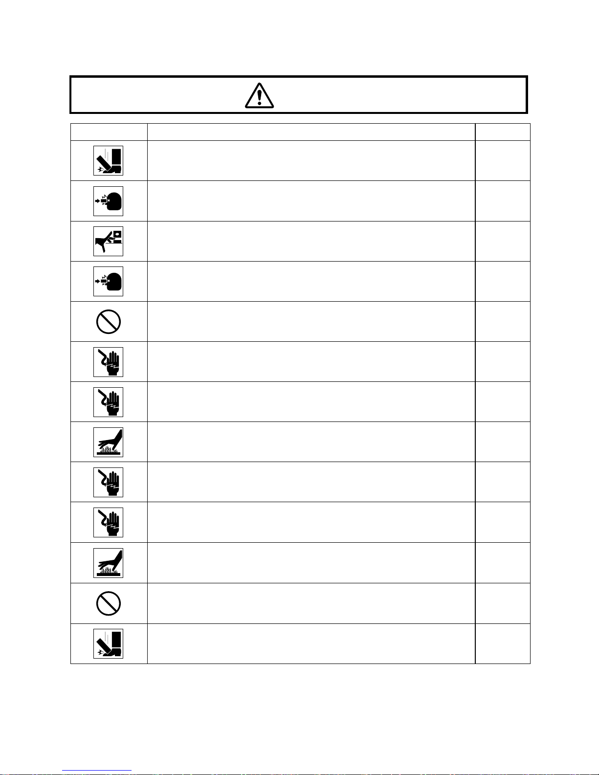
SAFETY CAUTIONS
Icons Prevention item Page
To prevent falling during use and movement, secure each unit.
15
To avoid injury to the eye and nose whilst moving the base unit,
make sure that you have a clear view of the slit lamp and the
patient's face.
29
For the safety of the operator and the patient, do not place fingers
between moving parts.
29
To avoid injury to the patient’s head, incline the illumination unit
holding the base unit.
30
To avoid causing discomfort to the patient or any damage to the
patient's eye, keep the illumination at its minimum during adjustment.
30
To avoid electric shocks, do not attempt overhauling, rebuilding or
repairs. Ask your dealer for repair.
36
When replacing the lamp, switch off the power supply and remove
the power cable to avoid electric shocks.
48
Beware of high temperatures when replacing the lamp immediately
after switching it off: these could cause burns.
48
When replacing fuses, first switch off the power supply and remove
the power cable to avoid electric shocks.
50
Before carrying out daily care, remove the power cable (to avoid
electric shocks) and wait until the lamp house has cooled (to avoid
burns).
51
Do not touch parts inside the lamp house cover during operation
and immediately after switching off the power supply: this could
cause burns.
51
The base contains strong springs. Do not attempt to disassemble
or burn the base, as the springs could cause injury by shooting out
of it.
52
To prevent falling during use and mov ement, secure optional accessories.
53
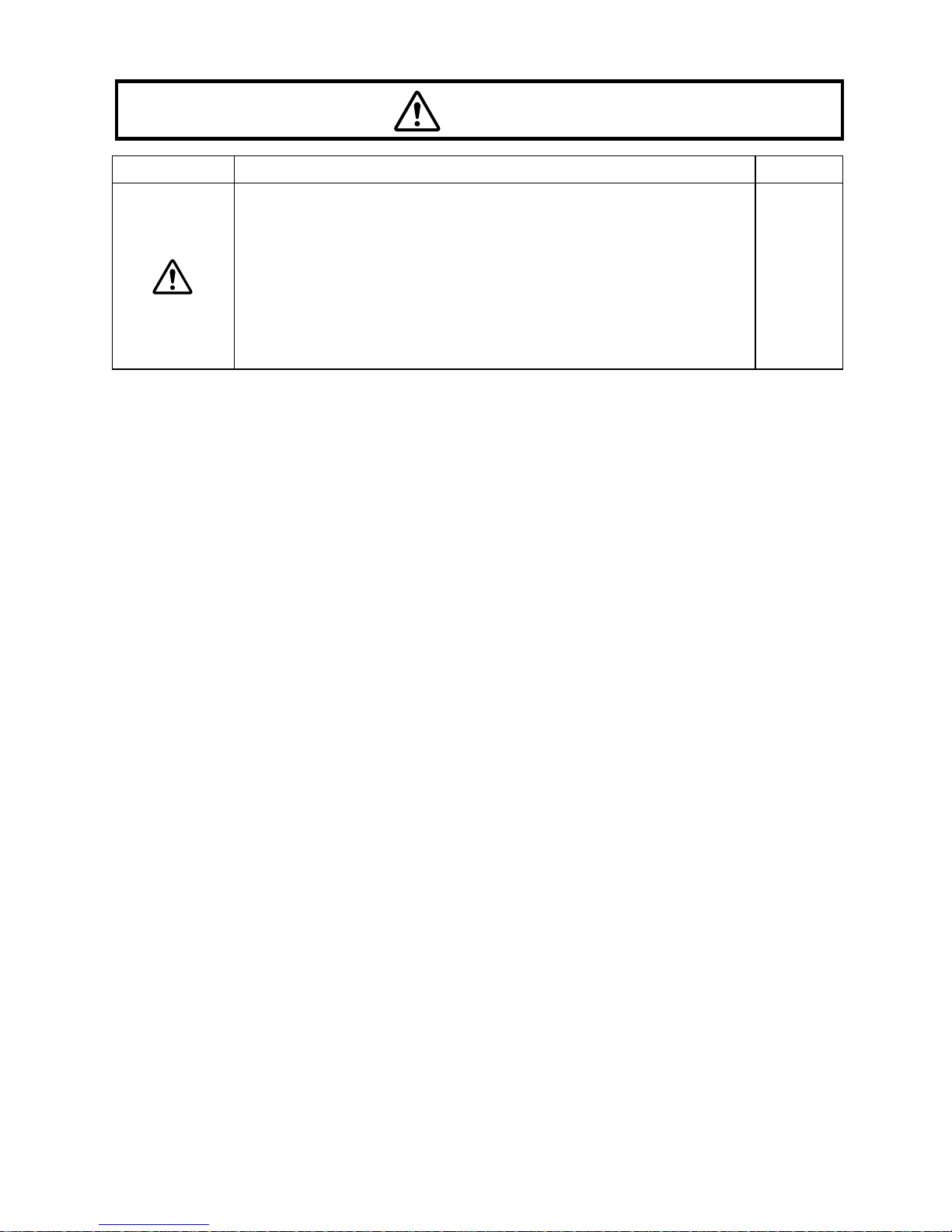
CAUTION
Page 7
5
This instrument has been tested (with 120V/230V) and found to
comply with IEC60601-1-2: 2001.
This instrument radiates radio frequency energy within standard
and may affect other devices in vicinity.
If you have discovered that turning on/off the instrument affects
other devices, we recommend you change its position, keep a
proper distance from other devices, or to change the outlet.
Please consult the dealer from whom you purchased the equipment for any questions.
––
Icons Prevention item Page
CAUTION
Page 8

6
MAINTENANCE
USER MAINTENANCE
To maintain the safety and performance of the instrument, unless done by an authorized service engineer, never attempt to do maintenance of items other than those specified here in.
For details about maintenance, read the description of this manual.
REPLACING THE ILLUMINATION LAMP
The illumination lamp can be replaced if necessary. For specific instructions, see page 48.
REPLACING THE FIXATION TARGET BULB (FOR BULB TYPE FIXATION TARGET ONLY)
The fixation target bulb can be replaced if necessary, see page 49.
REPLACING THE FUSE
Fuses on the primary side can be replaced, if necessary. For specific instructions, see
page 50.
ESCAPE CLAUSE
• TOPCON shall take no responsibility f or damage due to fire , earthquakes, actions by a third
party or other accidents, or the negligence and misuse of the user and use under unusual
conditions.
• TOPCON shall take no responsibility for damage derived from the inability to use this
equipment, such as a loss of business profit and suspension of business.
• TOPCON shall take no responsibility for damage caused by operations other than those
described in this Instruction Manual.
• Diagnoses made are the responsibility of qualified doctors and TOPCON shall take no
responsibility for the results of such diagnoses.
Page 9
7
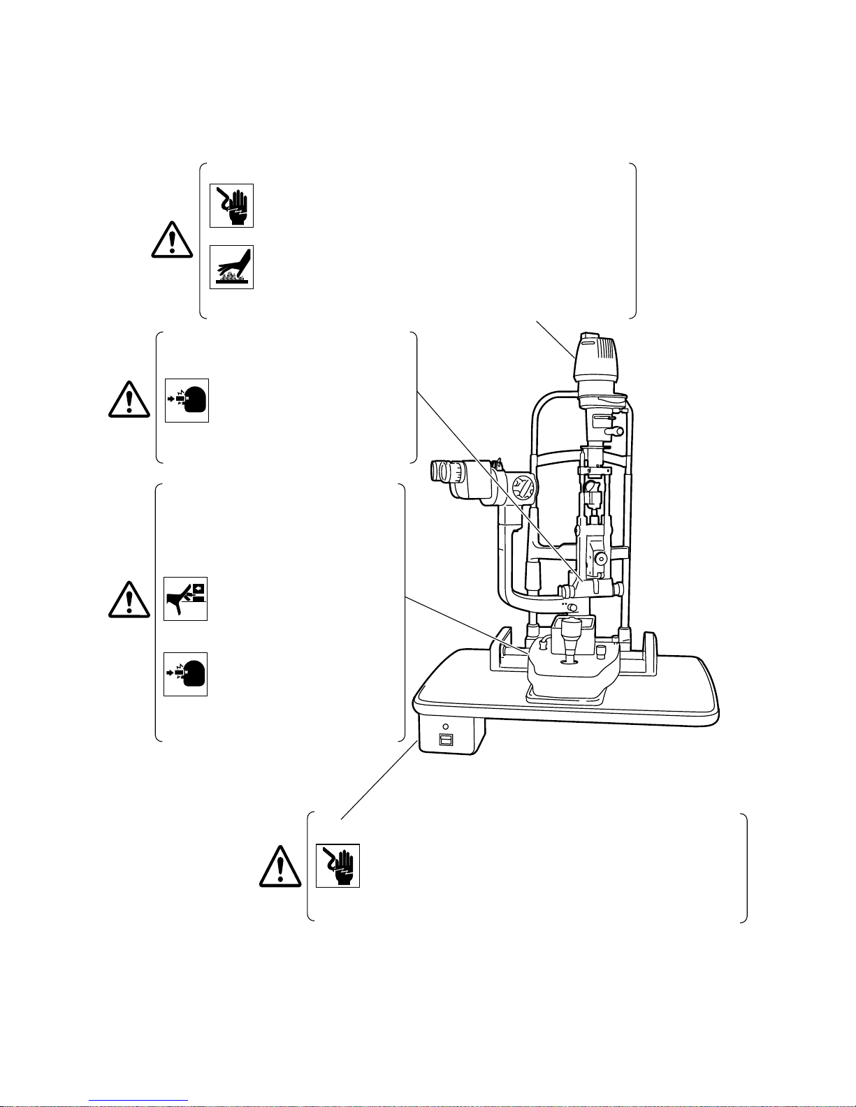
WARNING INDICATIONS AND POSITIONS
To ensure safety, warning labels are provided on the instrument body.
Use the instrument following these warning instructions. If any of the following labels are missing, contact your dealer or TOPCON (see the back cover).
CAUTION
• To prevent electric shocks, switch off the power supply and remove
the power cable before replacing the lamp.
Afin d’éviter tout choc électrique, coupez le contact et débranchez
le câble d’alimentation avant de remplacer l’ampoule.
• Do not replace the lamp immediately after switching it off: the high
temperatures could cause burns.
Afin d’éviter toute brûlure, prenez garde à la température élevée
de l’ampoule lorsque le remplacement de celle-ci se fait immédiatement après avoir coupé l’alimentation électrique.
CAUTION
• To prevent electric shocks, turn off the power switch and remove
the power cable before replacing fuses.
Afin d’éviter tout choc électrique, coupez le contact et débranchez
le câble d’alimentation avant de remplacer les fusibles.
• Use the specified fuse.
Utilisez des fusibles de même type et de même valeur.
CAUTION
To avoid injury to the patient’s head,
incline the illumination unit slowly
while holding the base unit.
Afin d’éviter toute blessure à la tête
du patient, inclinez l’unité d’illumination lentement tout en maintenant la
base de l’instrument.
CAUTION
When operating the base unit,
please note the following:
Pendant la manipulation de la base
de l’instrument, veuillez prendre
les précautions suivantes;
• Beware of catching fingers in
the moving parts.
Prenez garde aux pièces
mobiles afin d’éviter de coincer
les doigts.
• Avoid hitting the patient’s eyes
or nose.
Gardez une distance de travail
appropriée afin d’éviter le contact avec les yeux et le nez du
patient.
* The illustration depicts the SL-D7 type
.
Page 10

8
CONTENTS
INTRODUCTION.................................................................................................1
DISPLAYS FOR SAFE USE................................................................................3
SAFETY CAUTIONS...........................................................................................4
MAINTENANCE...................................................................................................6
USER MAINTENANCE........................................................................................6
ESCAPE CLAUSE...............................................................................................6
WARNING INDICATIONS AND POSITIONS......................................................7
CONFIGURATION
NAMES OF MAIN BODY COMPONENTS........................................................10
STANDARD ACCESSORIES............................................................................11
COMPONENTS
COMPONENTS.................................................................................................13
ASSEMBLY PROCEDURE
SECURING THE INSTRUMENT TYPE TABLE TOP........................................15
SECURING THE UNIT TYPE TABLE TOP.......................................................16
SECURING THE PATIENT GRIP PG-1(OPTIONAL ACCESSORY)................16
SECURING THE CHINREST BASE PLATE.....................................................17
SECURING THE BASE UNIT AND RAIL COVER............................................17
SECURING THE BINOCULAR TUBES.............................................................18
SECURING THE ILLUMINATION UNIT............................................................18
REMOVING THE ILLUMINATION UNIT PAD...................................................19
CONNECTING AND SECURING OF CABLES.................................................20
FITTING THE CHINREST TISSUE...................................................................21
FITTING THE CAP............................................................................................21
SECURING THE TONOMETER MOUNT SO-TM1 (OPTIONAL ACCESSORY)21
COUNTER BALANCING THE VERTICAL MOVEMENT...................................23
PREPARATIONS
POWERING ON ................................................................................................25
ADJUSTING THE DIOPTER AND PUPILLARY DISTANCE (PD)....................25
OPERATION PROCEDURE
FIXING THE PATIENT’S FACE AND FIXATION ..............................................27
OPERATING THE MICROSCOPE UNIT ..........................................................28
OPERATING THE BASE AND FOCUSING......................................................29
OPERATING THE ILLUMINATION UNIT..........................................................30
ENDING PROCEDURE.....................................................................................35
TROUBLESHOOTING
TROUBLESHOOTING GUIDE..........................................................................36
SPECIFICATIONS AND PERFORMANCE
SPECIFICATIONS AND PERFORMANCE.......................................................37
ELECTROMAGNETIC COMPATIBILITY ..........................................................39
ELECTRIC RATING ..........................................................................................42
Page 11

9
SYSTEM CLASSIFICATION .............................................................................43
PURPOSES OF USE ........................................................................................43
OPERATION PRINCIPLES...............................................................................43
SYSTEM CONFIGURATION.............................................................................44
SHAPE OF PLUG..............................................................................................45
SYMBOL............................................................................................................45
MAINTENANCE AND CHECKUPS
MAINTAINING THE PRECISION......................................................................46
PERIODIC MAINTENANCE..............................................................................47
DAILY CARE .....................................................................................................47
PLACING AN ORDER FOR CONSUMABLES..................................................48
REPLACING ILLUMINATION LAMPS...............................................................48
REPLACEING THE FIXATION TARGET BULB................................................49
REPLACING FUSES.........................................................................................50
RESTOCKING CHINREST TISSUE..................................................................50
DAILY CARE .....................................................................................................51
CLEANING APPLIED PARTS...........................................................................51
CLEANING LENSES AND MIRRORS...............................................................51
CLEANING THE SLIDING PLATE, RAIL AND WHEEL SHAFT.......................52
DISPOSAL OF THE PRODUCT........................................................................52
OPTIONAL ACCESSORIES
DIGITAL CAMERA UNIT DC-1..........................................................................53
ELECTRONIC FLASH DEVICE FD-21..............................................................54
BEAM SPLITTER ..............................................................................................55
TV RELAY LENS...............................................................................................55
TV RELAY LENS TL-54/55 (BUILT-IN BEAM SPLITTER TYPE) .....................56
TV ATTACHMENT TL-56..................................................................................56
TV ATTACHMENT TL-57..................................................................................57
BACKGROUND ILLUMINATION BG-4 .............................................................57
BACKGROUND ILLUMINATION BG-2GN........................................................57
OBSERVATION TUBE......................................................................................58
YELLOW FILTER UNIT.....................................................................................58
12.5X MEASURING EYEPIECE........................................................................58
20X EYEPIECE .................................................................................................58
APPLANATION TONOMETER..........................................................................58
HRUBY LENS....................................................................................................59
PARALLEL BINOCULAR TUBE PB-2...............................................................59
AUXILIARY SPRING SO-AS 1,2,3....................................................................59
PATIENT HANDLE PG-1...................................................................................59
ADAPT COVER SO-AC1, 2, 3, 4, 5...................................................................59
Page 12
10
CONFIGURATION
CONFIGURATION
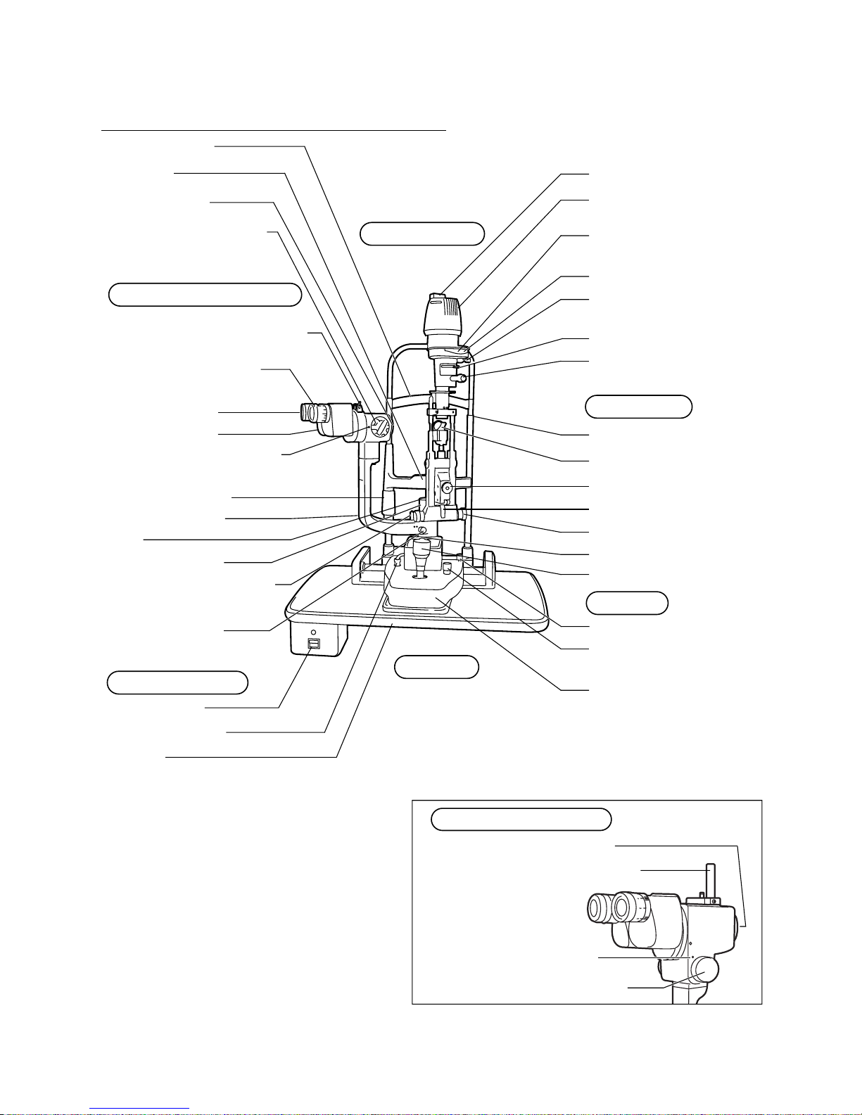
NAMES OF MAIN BODY COMPONENTS
*1,2) A model without exciter filter for slit
lamp/barrier filter for slit lamp is also
available.
*3) A model without table unit is also
available.
Plug
Lamp house cover
Aperture/slit length
display window
Color conversion filter
selector lever
Filter selector lever
Aperture/slit-
length control
Canthus marker
Mirror
Centering knob
Inclination lever
Slit-width control knob
Photo switch
Control lever
Base locking knob
Brightness adjustment
knob
Base
Forehead rest
Chinrest
Objective lens
Magnification selector
handle
*2 Barrier filter selector lever
Diopter adjusting ring
12.5× eyepiece
Binocular tubes
Magnification index mark
Chinrest adjuster
Microscope arm
Cap
Illumination arm locking
knob
Power switch
*3 Table
Base relay cable
Microscope arm
locking knob
Illumination arm
Illumination Unit
Table
Power Supply
SL-D7 Microscope Unit
Base Unit
Chinrest Unit
*1 Exciter filter
SL-D8Z Microscope Unit
Magnification selector handle
Magnification index mark
Objective lens
Tonometer mount
Page 13
11
CONFIGURATION
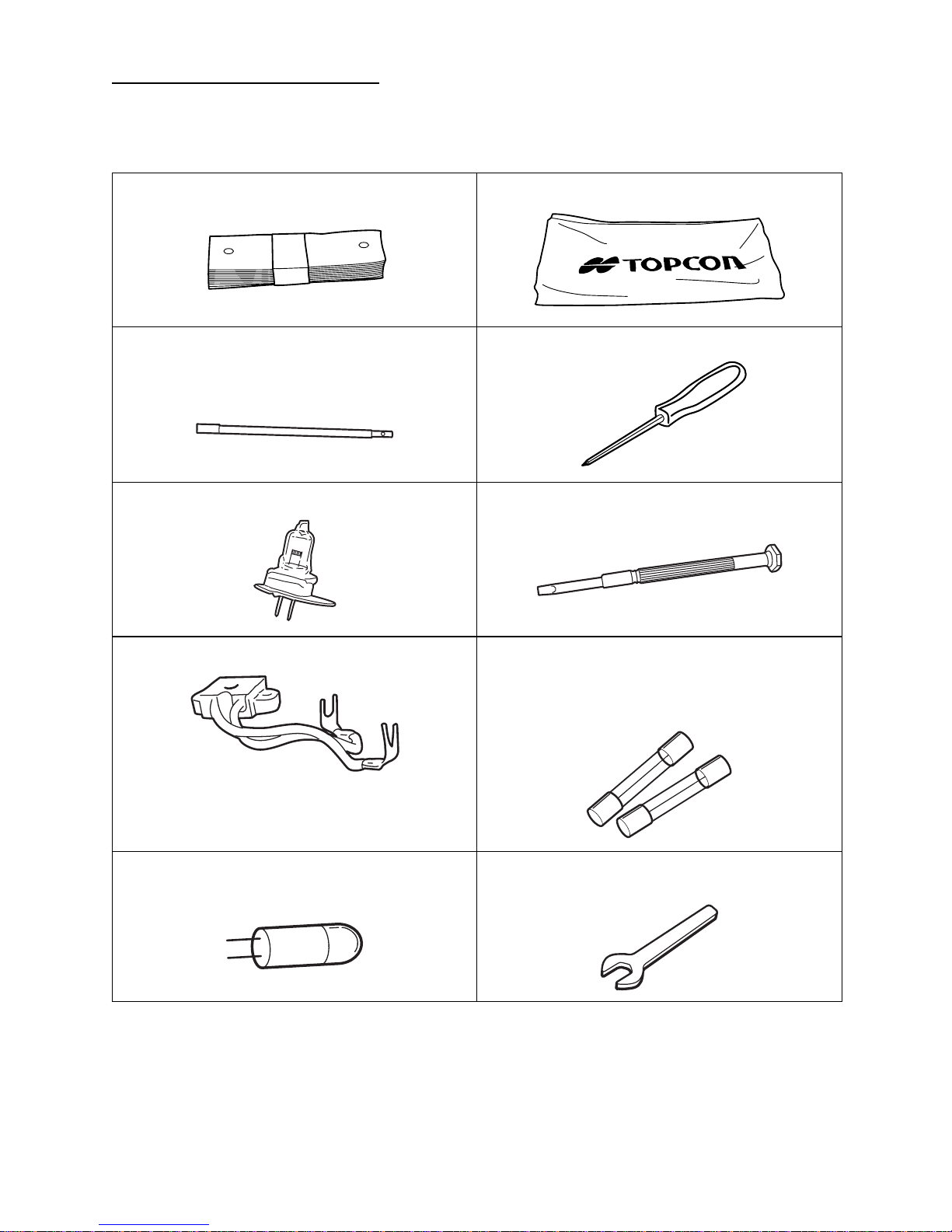
STANDARD ACCESSORIES
Make sure that all the following standard accessories are included.
Figures in parentheses are the quantities.
Chinrest tissue (1) Dust-cover (1)
Test rod (1)
(This is not always included with the standard
specifications.)
Crosshead screwdriver (1)
Spare illumination lamp (1) Screwdriver (1)
Spare socket (1) Spare fuse (2)
(Depending on specification, quantity may differ, or this item may not be included in stan-dard accessories.)
Spare fixation target bulb (1)
(for bulb type fixation target only)
Spanner (1)
(for instrument type table top only)
Page 14
12
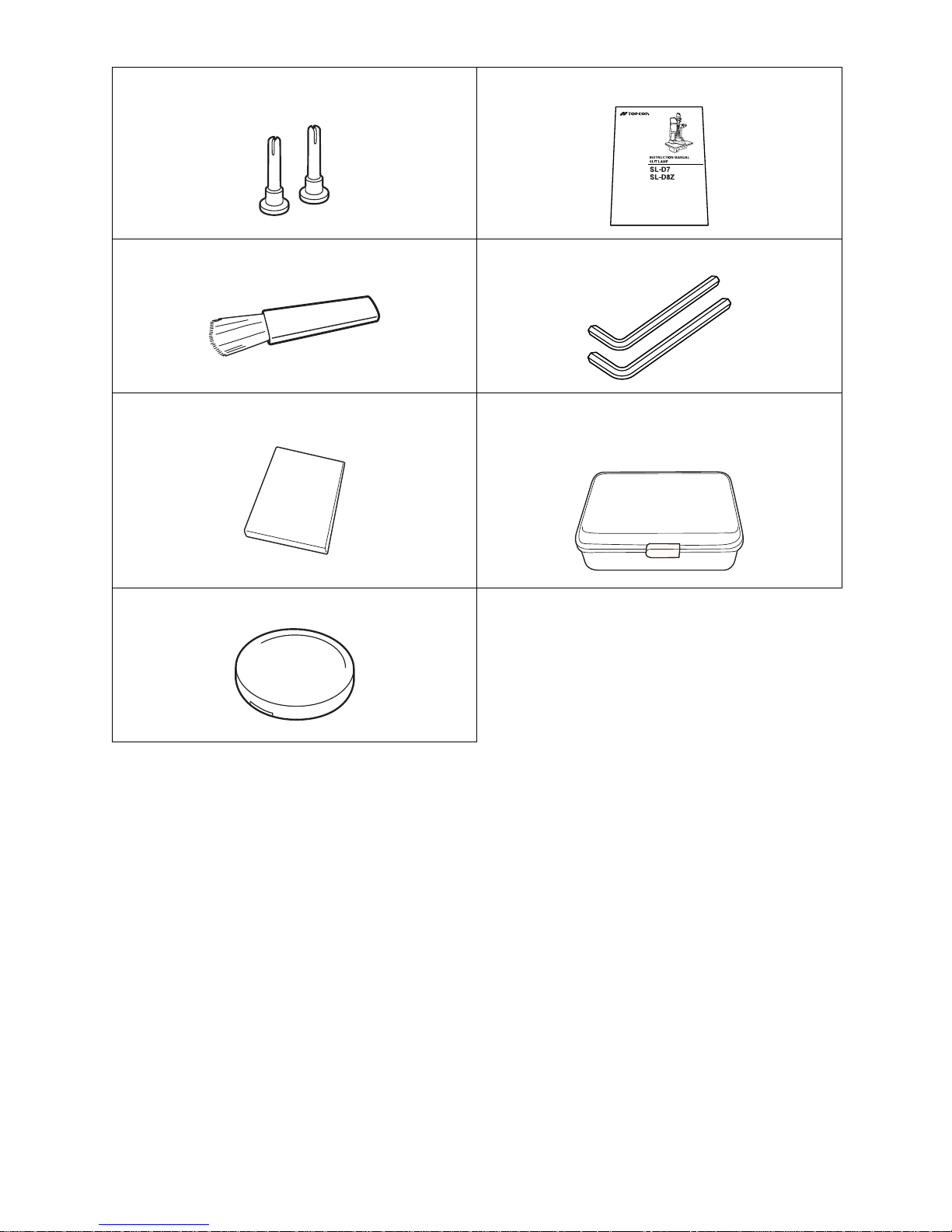
CONFIGURATION
For optional accessories, see “Optional Accessories” on page 53.
Spare chinrest tissue pin (2) Instruction Manual (1)
Cleaning brush (1) Hexagon wrench (2)Attached document (1)
Square mirror (1) Accessory case (1)
(This is not always included with the standard
specifications.)
Cap (1)
Page 15
13
COMPONENTS
COMPONENTS
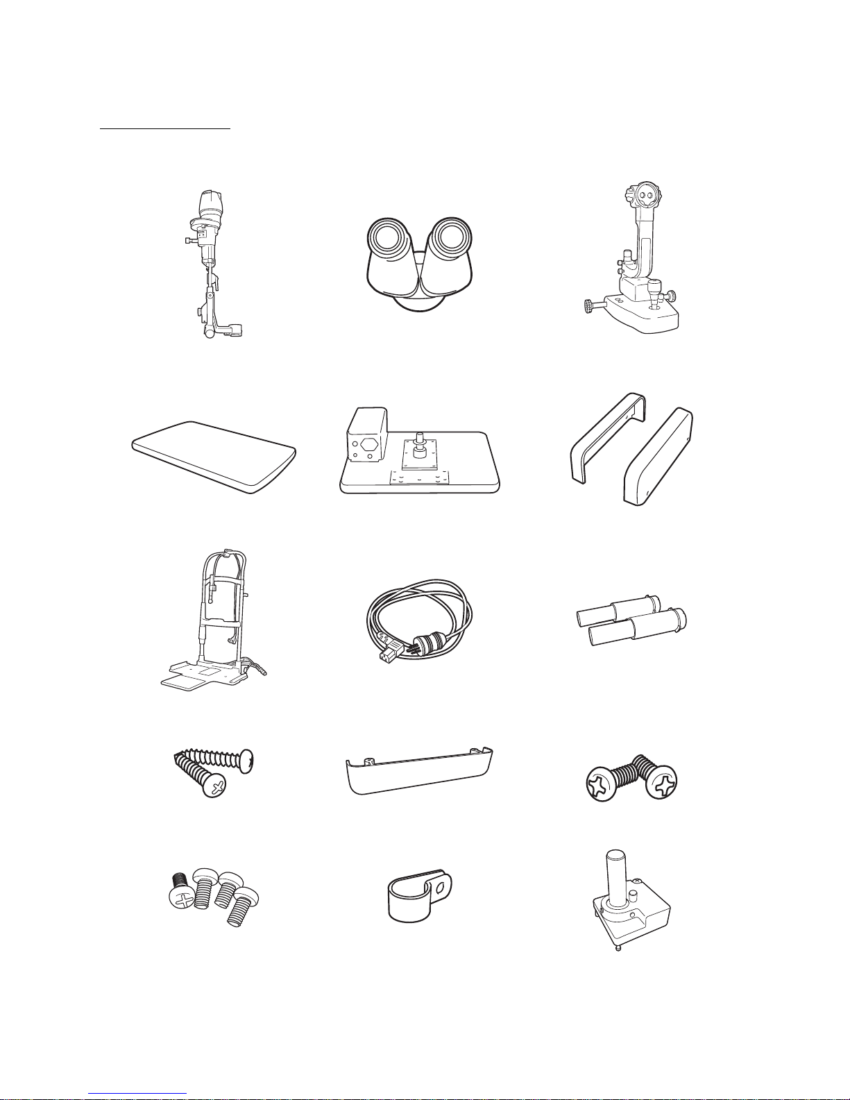
COMPONENTS
(1) Illumination unit (2) Binocular tubes (3) Base unit
* The photo shows the SL-D7 type.
(4) Instrument type table top
(w/power supply)
(4)’ Unit type table top (5) Rail cover
(6) Chinrest unit (7) Power cable (8) Auxiliary spring
(9) Setscrew (10) Cable cover (11) Cable cover fixing screw
(12) Rail cover fixing screw (13) Cable clip (14) Tonometer maunt SO-TM1
Page 16

14
COMPONENTS
* (4) or (4)’ table top is not included, depending on the specifications.
* (6) Depending on chinrest and (14) Tonometer mount might not be included.
Article name Qty Article name Qty
(1) Illumination unit 1 (8) Auxiliary spring 2
(2) Eyepiece unit 1 (9) Setscrew 2
(3) Base unit 1 (10) Cable cover 1
(4) Instrument type table top
(w/power supply)*
1 (11) Cable cover fixing screw 2
or (4)’ Unit type table top* 1 (12) Rail cover fixing screw 4
(5) Rail cover 2 (13) Cable clip 1
(6) Chinrest unit* 1 (14) Tonometer maunt SO-TM1* 1
(7) Power cable 1
Page 17
15
ASSEMBLY PROCEDURE
ASSEMBLY PROCEDURE
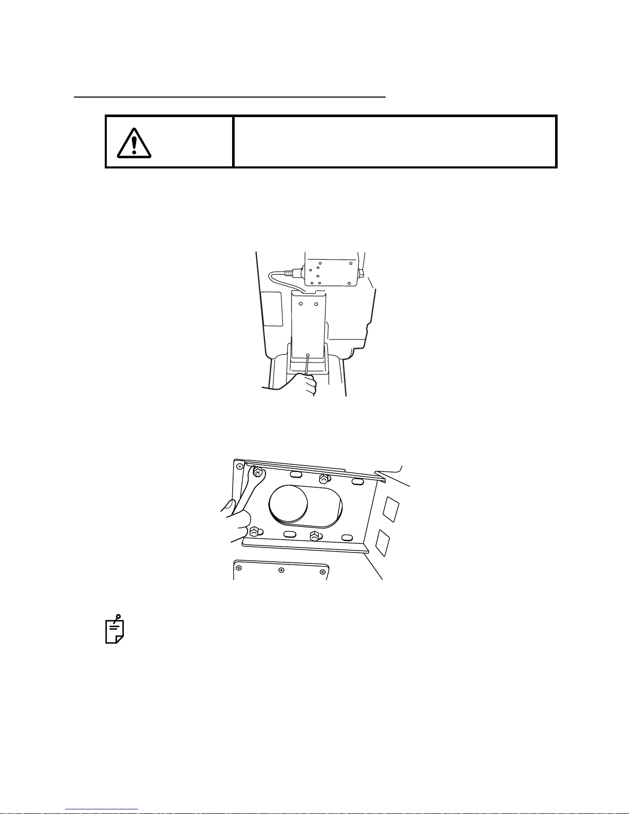
SECURING THE INSTRUMENT TYPE TABLE TOP
FITTING TO AUTOMATIC INSTRUMENT TABLE AIT-20
(except for USA and Canada)
/AIT-15
(allarea)
/AIT-16
(allarea)
1
Remove the cover of the instrument table. Remove the 3 screws of the cover (AIT-20
only: For details, refer to the instruction manual of AIT-20.)
2
Place the tabletop on the instrument table, and secure it with the 4 bolts attached to the
instrument table. To reverse the direction of the instrument table, remove the power supply from the bottom of the table top and secure it on the opposite side.
CAUTION
To prevent falling during use and movement, secure each unit.
Connect the power cable to the table outlet and power supply of the instrument
table. Place the excess cable inside the cover, and attach the cover.
Page 18
16
ASSEMBLY PROCEDURE
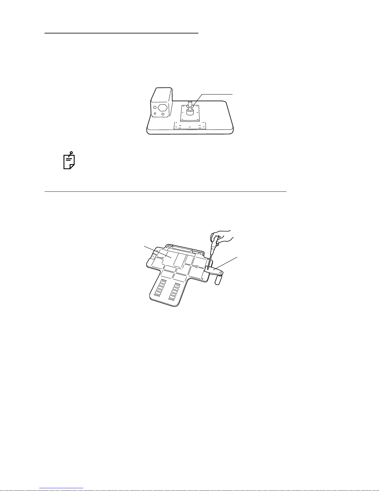
SECURING THE UNIT TYPE TABLE TOP
1
Remove the plastic washer from the unit type table top, which is taped to the shaft assembly.
2
Insert the plastic washer, together with the shaft, into the cavity for the ophthalmic unit
arm.
SECURING THE PATIENT GRIP PG-1(OPTIONAL ACCESSOR
Y)
1
Align the patient grip with a groove on the rear of the chinrest base.
2
Fix the patient grip with screws.
In the unit type table top, the power supply is fitted to attach the ophthalmic unit on
the right hand side. When attaching the ophthalmic unit on the left-hand side,
remove the power supply and reattach it to the right hand side (with 4 screws).
Washer
Patient grip
Chinrest base
Page 19
17
ASSEMBLY PROCEDURE
SECURING THE CHINREST BASE PLATE
1
Secure the chinrest base plate to the unit type table top with 2 screws (9).
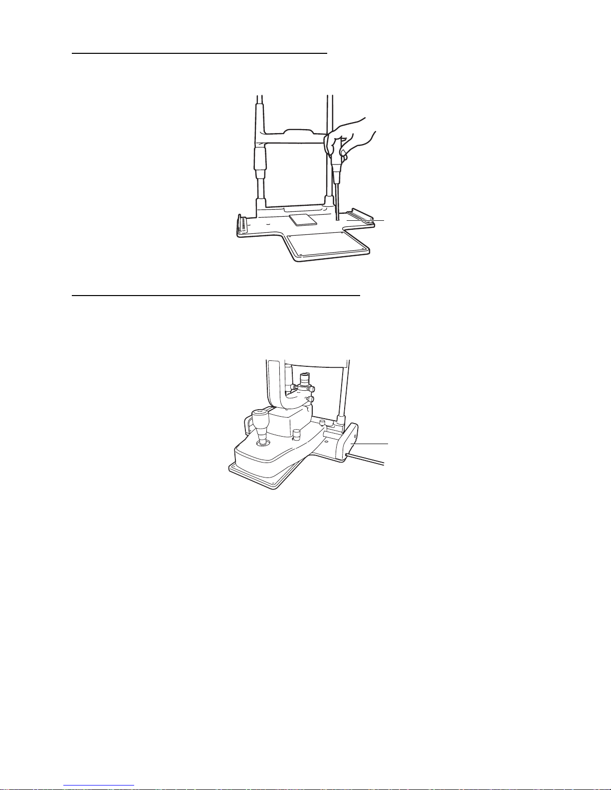
SECURING THE BASE UNIT AND RAIL CO
VER
1
Align the wheel of the base unit with the rail of the chinrest base plate.
2
Secure the rail covers with 4 screws (12): (2 screws each on the right and left sides).
Chinrest base plate
Rail cover
Page 20
18
ASSEMBLY PROCEDURE
SECURING THE BINOCULAR TUBES
1
Align the pin of the microscope unit with the groove on the binocular tubes, and fit the
screw with a hexagon wrench.
In the model without excitor/barrier filter, fit binocular tube with the fixing screw.
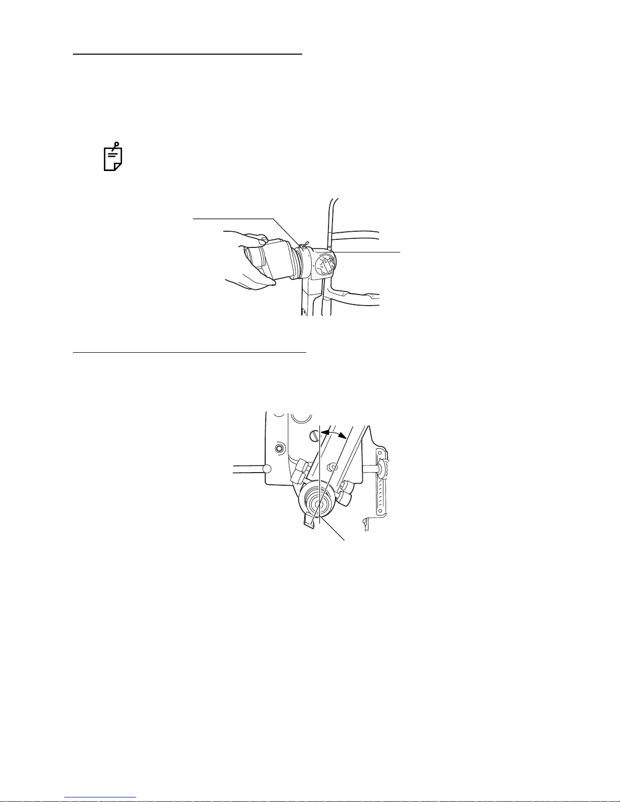
SECURING THE ILLUMINATION UNIT
1
Loosen the microscope arm locking-knob of the base unit, manually turn the shaft and tilt
the guide rod-shaft index 30-60
°
, then refasten the microscope-arm locking-knob.
Make sure you do not touch the lens surfaces.
Screw
Microscope unit
* The illustration
depicts the SL-D7
30° - 60°
Indices
Page 21

19
ASSEMBLY PROCEDURE
2
Loosen the fixing screw on the outside of the fitting cavity of the illumination unit with a
screwdriver. Align indices and slowly lower the illumination unit onto the shaft of the base
unit.
3
Firmly tighten the fixing screw with a screwdriver.
REMO
VING THE ILLUMINATION UNIT PAD
1
Remove the rubber band and slowly withdraw the protection pad from the slit operation
mechanism of the illumination unit.
While assembling the illumination unit, take care not to get your fingers caught.
Indices
Protection pad (for transportation)
Page 22

20
ASSEMBLY PROCEDURE
CONNECTING AND SECURING OF CABLES
1
Remove the tape from the lamp house cover of the illumination unit. Plug the cable from
the upper part of the chinrest into the illumination unit.
2
Connect the cable from the lower part of the chinrest unit and the power cable to the
power supply.
3
Pass the 5 pin connector from the metal plug connected to the power supply through the
hole of the chinrest and connect to the base unit.
4
Fit the cable cover with 2 screws (11).
5
Pull the base unit toward the side of the operator, then lock.
Attach the cables to the back of the table with the cable clip (13).
6
Move the base unit and illumination unit, and make sure there is enough cable to allow
free movement of the base unit in all directions.
Plug
Fixation cable
Illumination cable
Power cable
Page 23

21
ASSEMBLY PROCEDURE
FITTING THE CHINREST TISSUE
1
Remove the chinrest tissue pins.
2
Take approximately one-fifth of the pad of chinrest tissues and secure this at each end
with the pins.
FITTING THE CAP
1
Fit the cap to the shaft aligning the guide rod with the groove in the cap.
SECURING THE TONOMETER MOUNT SO-TM1 (OPTIONAL ACCESSOR
Y)
Depending on specification, SO-TM1 may be included in standard accessories.
1
Align the locating pin of SO-TM1 into the holes of the microscope, and fasten the screw.
Screw
Locating Pin
The holes
Page 24

22
ASSEMBLY PROCEDURE
2
Remove the fixing knob of the microscope, and secure the eyepieceunit, etc with the
packaged screw.
3
Applanation tonometer R900 type, Photokeratoscope attachment, etc could be mounted
on SO-TM1.
Screw
Fixing knob
Page 25

23
ASSEMBLY PROCEDURE
COUNTER BALANCING THE VERTICAL MOVEMENT
When accessories, including the photography unit, are fitted to the main body, the vertical
counter-balance movement may need to be adjusted. To correct this, auxiliary springs must
be fitted.
Each auxiliary spring consists of 2 identical springs.
Do not use different springs in a set.
Major Combinations of Accessories and Necessary Auxiliary Springs
Accessories
Auxiliary Spring type
Tonometer
is not fitted
Tonometer
is fitted
TV relay lens TL-55 + SONY DXC-33 (DXC-390)
–––
Standard
auxiliary
spring
TV attachment TL-56 +
Nikon Microsystem (Coolpix + Adapter lens)
Digital camera unit DC-1
TV relay lens TL-54 + JVC KY-F70
Standard
auxiliary
spring
Standard
auxiliary
spring
Electronic flash device FD-21 + Digital camera unit DC-1
Electronic flash device FD-21 (w/TV relay lens TL-55) +
SONY DXC-390
Beam splitter + Observation tube Auxiliary
spring
SO-AS1
Still camera attachment SR-53 + Nikon mount + Fuji S2 Pro
Beam splitter + TV relay lens (1/2C) + JVC KY-F70
Auxiliary
spring
SO-AS2
Electronic flash device FD-21 + beam splitter + TV relay lens
TL-53 + SONY DXC-390
Electronic flash device FD-21 (w/TV relay lens TL-54) +
JVC KY-F70
Electronic flash device FD-21
(w/still camera attachment SR-53) + Fuji Finepix S2 Pro
Auxiliary
spring
SO-AS1
Auxiliary
spring
SO-AS3
Electronic flash device FD-21 + beam splitter +
TV relay lens (1/2C) + JVC KY-F70
Electronic flash device FD-21
(w/still camera attachment SR-52) + Nikon D1 (X)
Auxiliary
spring
SO-AS2
Auxiliary
spring
SO-AS3
Page 26

24
ASSEMBLY PROCEDURE
COUNTER-BALANCE PROCEDURE
1 Turn the control lever clockwise and raise the base to the top position, remove the center
screw and take off the cover.
2 Insert the auxiliar y spring unit ver tically into the auxiliary spr ing por t, with the flange face
turned upwards. (Make sure that the spring is inserted into the groove in the bottom of the
port.)
3 Open the auxiliary spring unit with the auxiliary spring port, and lightly push the spring till it
stops. (A large screwdriver, a flat sheet metal tool, a coin, etc. can be used to this end.)
4 With the auxiliary spring unit lightly touching the stopper, turn about 90° (in either direc-
tion), then release. The auxiliary spring locks into the positioning groove and assembly is
complete. (To remove the auxiliary spring, lightly press it down to the stopper, rotate it 90°
and remove from the port.)
Cover
Auxiliary spring port
Page 27

25
PREPARATIONS
PREPARATIONS
POWERING ON
1 Connect the power cable.
2 Turn ON the POWER switch.
ADJUSTING THE DIOPTER AND PUPILLARY DISTANCE (PD)
In case that no test rod is provided, set the diopter scale to your diopter by turning the diopter
adjustment ring.
1 Insert the test rod into the rotation shaft cavity, and set the black face square with the
microscope.
2 Set the eyepiece with scale to the non-dominant eye side.
3 Turn ON the POWER switch, and place the brightness adjustment knob in an intermedi-
ate position.
4 Adjust the illumination φto 10mm by adjusting the slit adjustment knob and aperture/slit-
length selector knob.
5 Turn the diopter adjusting ring of the eyepiece with scale ( ) fully counter-clockwise.
6 Turn the diopter adjusting r ing clockwise and stop when both the scale ( ) and test rod
can be clearly seen.
7 Read the value on the diopter scale of the stop position. The value shows the diopter (D).
8 Set the diopter scale of the other eyepiece to the read value.
9 Set the eyepiece with scale ( ) to the dominant eye side, and adjust the diopter scale of
the dominant eye as in steps 5 and 6.
10 After adjusting the diopter, turn the slit adjustment knob until the slit width is about 1mm,
then check if the slit image projected on the test rod can be clearly seen with both right
and left eyes.
NOTICE
To ensure sharp observation of slit images, alwa ys carry out the
diopter and PD adjustments.
Test rod
* The illustration
depicts the SL-D
7
Page 28

26
PREPARATIONS
11 Holding the prism box, look through the eyepiece with both eyes, and adjust the pupillary
distance so that the image projected on the test rod can be seen without diplopia (double
vision), and appears to be three dimensional.
Prism box
Diopter adjusting ring
Diopter scale
* The illustration depicts
the SL-D7 type.
Page 29

27
OPERATION PROCEDURE
OPERATION PROCEDURE
FIXING THE PATIENT’S FACE AND FIXATION
The model without a fixation target is also available.
1 Place the patient's chin on the chinrest with his forehead against the forehead rest.
2 By rotating the chinrest adjuster, align the patient's eye with the canthus marker on the
chinrest frame.
3 Ask the patient to look at the fixation target with the eye that is not being examined.
To change the patient's fixation point, hold the fixation target at the end opposite to the
target and adjust accordingly.
When using the fixation target with diopter adjustment (A), slide the diopter adjustment knob so that the patient can see the following target ( ). The ring target can
be adjusted within a range of -15D to +10D.
The luminous fixation target is used for myopia of -15D or more.
When replacing targets, remove the target by pulling
gently whilst supporting the opposite end.
Forehead rest
Canthus marker
Chinrest
Chinrest adjuster
(A)Fixation target with
diopter adjustment
(B) Luminous fixation target
Diopter adjusting
ring
Fixation target unit
Fixation target lever
Page 30

28
OPERATION PROCEDURE
OPERATING THE MICROSCOPE UNIT
Turn the magnification selector to set a magnification value against the magnification index
mark.
SL-D7
SL-D8Z
For the ov erall magnification in conjunction with magnification marks of the magnification selector handle, see page 37.
Magnification selector
handle
Magnification index mark
Magnification index mark
Magnification selector handle
Page 31

29
OPERATION PROCEDURE
OPERATING THE BASE AND FOCUSING
1 For major horizontal movements, hold the control lever in the upright position and move
the entire base.
2 For fine adjustments, move the control lever in the required direction.
3 The base can be raised by turning the control lever clockwise, and lowered by turning the
control lever counter-clockwise.
4 To fix the base, fasten the base locking knob.
CAUTION
To avoid injury to the eye and nose whilst moving the base
unit, make sure that you have a clear view of the slit lamp and
the patient's face.
CAUTION
For the safety of the operator and the patient, do not
place fingers between moving parts.
NOTICE
To prevent dropping the base locking knob from the base, do
not loosen the knob too much.
• Rough focusing is carried out with major movements, following step 1-3.
• Fine focusing is done with the microscope, following steps 2 and 3.
Base locking knob
Base
Control lever
Page 32

30
OPERATION PROCEDURE
OPERATING THE ILLUMINATION UNIT
ADJUSTING THE BRIGHTNESS
Turn the brightness adjustment knob.
The brightness of the illumination light can be adjusted to the preferred illumination setting.
ADJUSTING THE SLIT WIDTH
Turn the slit-width control knob.
The slit width can be changed gradually between 0 and 14mm (14mm=circle).
CAUTION
To avoid injury to the patient’s head, incline the illumination
unit holding the base unit.
CAUTION
To avoid causing discomfort to the patient or damage to the
patient's eye, keep the illumination at its minimum during
adjustment.
NOTICE
• Adjust the slit width according to the results of the investigation.
• The slit-width scale should be used as a guideline.
• When using the square mirror, incline the illumination unit at
least 10º.
• To protect the patient, use the heat absorption filter, as
required.
Brightness adjustment
knob
Slit-width control knob
Page 33

31
OPERATION PROCEDURE
CHANGING THE APERTURE/SLIT LENGTH
Turn the aperture/slit-length control knob.
When the slit is fully opened, 6 types of spot illumination (φ14, φ10, φ5, φ2, φ1, φ0.2) are av aila-
ble. The slit width can be changed gradually from 1mm to 14mm.
TURNING THE SLIT
Horizontally rotate the aperture/slit-length control knob.
This directly changes the slit image from vertical to horizontal. In this mode, the slit angle can
be read off the angle scale.
SWINGING THE SLIT SIDEWAYS
Loosen the centering knob and swing the illumination unit right and left.
This provides indirect illumination displacing the slit light from the microscope center.
By fastening the centering knob, the slit light returns to the center of the vision field.
The spot illumination size and slit length are displayed on the aperture/slit-length
display window.
This function is used for scanning observation and observation with indirect illumination.
Aperture/slitlength display win-
Aperture/slitlength control
Aperture/slitlength control
Slit-angle scale
Page 34

32
OPERATION PROCEDURE
INCLINED ILLUMINATION
Press to unlock the inclination lever and pull.
The illumination unit is inclined for inclined illumination up to 20° in 5° steps.
REFLECTION MIRROR
For this instrument, a battledore mirror and a square mirror are availab le . For normal observation, the battledore mirror is used.
However, if the arm angle scale, which represents the angle formed by the illumination arm
and micro-scope arm, reads approx. 3° to 10° and the observation light flux is disturbed b y the
battledore mirror, then the square mirror should be used.
The square mirror is to be used when the arm angle is opened to more than 10°.
This function is used for observing a horizontal cross section, and for corner angle
and fundus observation.
The square mirror is standard accessory.
Centering knob
Inclination lever
Square mirrorBattledore mirror
Page 35

33
OPERATION PROCEDURE
REPLACING REFLECTION MIRRORS
Replace mirrors as follows, taking care not to touch the mirror and lens surfaces:
• Open the microscope arm and illumination arm 30° or more.
• Incline the illumination unit 10° or more.
• Pull out the battledore mirror, holding the slender part on both sides. To reinsert the battledore mirror, hold the slender part on both sides and insert.
• Insert the square mirror from the side recessed on the back.
• To pull out the square mirror, which has no handle, push it up with a pencil, or something
similar, as illustrated below.
CHANGING FILTERS
Move the filter selector lever right and left to select the required filter from the 5 types.
If you touch the mirror or lens surface, please clean this according to the process
on page 51 "Cleaning Lenses and Mirrors".
Square mirrorBattledore mirror
Green-colored
No filter ND filter
Blue filter or no filter ( )
Red-free filterHeat-absorption
filter
Aperture/slit length
display window
Filter selector lever
Aperture/slit length
control knob
Page 36

34
OPERATION PROCEDURE
AMBER FILTER
The amber filter is used to facilitate fundus observation.
The filter is inserted or removed by the amber filter selector lever.
FLUORESCENCE OBSERVATION
(EXCITER FILTER FOR SLIT LAMP/BARRIER FILTER FOR SLIT LAMP)
Fluorescence observation can be carried out using the exciter filter for slit lamp and barrier filter for slit lamp.
1 Turn the aper ture/slit-length display window anti-clockwise until the blue circle appears,
then insert the exciter filter for slit lamp into the illumination path.
2 Turn the barrier filter selector lever to the right and insert the barrier filter for slit lamp.
Amber filter selector
lever
ON
OFF
Aperture/slit-length
control knob
Aperture/slit-length
display window
Barrier filter selector lever
* The illustration depict
s
the SL-D7 type.
Page 37

35
OPERATION PROCEDURE
DIFFUSION LENS
When in use, the diffusion lens is set vertically in front of the reflection mirror.
When not in use, remove the lens from the light path.
ENDING PROCEDURE
Turn OFF the Power switch.
The diffusion lens is used for observing the entire object with a low magnifica-tion.
NOTICE
When using the diffusion lens, open the microscope arm and
illumination arm 30° to avoid friction of the diffusion lens and
illumination support. Also, fully open the slit; otherwise this
prevents sufficient light from entering.
Diffusion lens
* The illustration depicts
the SL-D7 type.
Page 38

36
TROUBLESHOOTING
TROUBLESHOOTING
TROUBLESHOOTING GUIDE
If you suspect a problem, check the possible cause by means of the check list below.
If the check list below does not solve the problem, or if the problem is not included in the list,
contact your dealer or TOPCON (see the back cover).
CAUTION
To avoid electric shocks, do not attempt overhauling, rebuilding or repairs. Ask your dealer for repair.
Check List
Problem Possible cause Check Page
Illumination lamp
does not work
Cable connection is
disconnected
Check cable connection. 20
Base relay cable is switched
off.
Connect the cable. 20
Plug of lamp house cover is
switched off
Insert plug. 20
POWER switch is OFF Turn ON POWER switch. 25
Brightness adjustment knob is
the minimum
Turn up brightness adjustment
knob.
30
Illumination lamp is broken
Replace it with a new
illumination lamp.
48
Socket has deteriorated Replace it with a new socket. 49
Illumination field is
not uniform/is
shady/is dark
Filter selector lever is out of
position
Click filter selector lever. 33
Fixation target lamp
does not work
Fixation cable is off Insert cable. 20
Fuse blows
Rated capacity of fuse is
incorrect
Use fuse with correct rating &
authorized fuse.
48, 50
Slit width narrows by
itself
Slit-adjustment knob torque
has been decreased
Readjust slit-width control knob
torque.
46
Page 39

37
SPECIFICATIONS AND PERFORMANCE
SPECIFICATIONS AND PERFORMANCE
SPECIFICATIONS AND PERFORMANCE
SL-D7 SL-D8Z
Microscope unit
Type Galileo type
Magnification Drum, 5-step magnification Manual zooming
Magnification steps 6/10/16/25/40 10, 16 and 25 w/clicks
Overall magnification
(actual vision field)
6.37 (φ35.1mm)/
9.94 (φ22.5mm)/
15.87 (φ14.1mm)/
25.37 (φ8.8mm)/
39.62 (φ5.6mm)/
6.35 - 31.75 (φ35.2 - φ7mm)
Eyepiece lens
Magnification: 12.5x
Diopter adjustment range: -5D - +5D
Binocular tubes PD adjustment: 55 - 78mm
Illumination unit
Illumination field
Slit width: 0-14mm, can be altered gradually(14mm=circle)
Slit length: 14-1mm, can be altered gradually(14mm=circle)
Aperture diameter: φ14, 10, 5, 2, 1, 0.2
Slit direction
Vertical to horizontal, can be altered gradually
Inclination: 5/10/15/20
Side swing
Filter
Blue filter, red-free filter, amber filter,
UV cut filter (normal use), IR cut filter (normal use),
ND filter (13% transmission), heat insulation filter, exciter filter for
slit lamp*1, barrier filter for slit lamp*
2
Illumination lamp 12V, 30W halogen lamp
Chinrest/forehead rest unit
Forward-backward move-
ment
90mm
Right-left movement 100mm
Vertical movement 30mm
Amount of movement in
all directions
15mm
Amount of vertical move-
ment of chinrest
80mm
Fixation target*
3
Fixation target with diopter adjustment
Luminous fixation target
Fixation lamp LED (Red) or bulb (white)
Page 40

38
SPECIFICATIONS AND PERFORMANCE
*1), *2) A model without exciter filter for slit lamp/barrier filter for slit lamp is also available.
*3) A model without fixation target is also available.
• The specification and design of the product can be altered for improvements without prior
notice.
SL-D7 SL-D8Z
Dimensions, Weight
Dimensions:
w/Table 550mm(W)x399mm(D)x760-790mm(H)
w/ Unit Table 440mm(W)x399mm(D)x760-790mm(H)
w/o Table 329mm(W)x349mm(D)x652-682mm(H)
w/o Table and Chinrest 329mm(W)x306mm(D)x652-682mm(H)
Weight: w/Table 19kg 19.5kg
w/ Unit Table 18kg 18.5kg
w/o Table 13kg 13.5kg
w/o Table and Chinrest 11.5kg 12kg
Table size 550mm x 370mm
Unit Table size 440mm x 350mm
Height from the top to
patient’s eye
375mm
Page 41

39
SPECIFICATIONS AND PERFORMANCE
ELECTROMAGNETIC COMPATIBILITY
This product conforms to the EMC Standard(IEC 60601-1-2:2001).
a MEDICAL ELECTRICAL EQUIPMENT needs special precautions regarding EMC and
needs to be installed and put into service according to the EMC information provided in the
ACCOMPANYING DOCUMENTS.
b Portable and mobile RF communications equipment can affect MEDICAL ELECTRICAL
EQUIPMENT.
c The use of ACCESSORIES, transducers and cables other than those specified, with the
exception of transducers and cables sold by the manufacturer of the EQUIPMENT or SYSTEM as replacement parts for internal components, may result in increased EMISSIONS or
decreased IMMUNITY of the EQUIPMENT or SYSTEM.
d The EQUIPMENT or SYSTEM should not be used adjacent to or stacked with other equip-
ment. IF adjacent or stacked use is necessary, the EQUIPMENT or SYSTEM should be
observed to verify normal operation in the configuration in which it will be used.
e The use of the ACCESSORY, transducer or cable with EQUIPMENT and SYSTEMS other
than those specified may result in increased EMISSION or decreased IMMUNITY of the
EQUIPMENT or SYSTEM.
Item Article code Model No. Length(m)
Flash Device FD-21 447909756 - Digital Camera Unit DC-1 D2 447939711 - Background illumination BG-2GN 446949680 - -
Slit Lamp trigger cable
447907100
447907200
- 0.9
4.0
IF cable 447938450 - 2.0
USB cable 447938877 - 3.0
Video cable 447938550 - 3.0
Guidance and manufacturer's declaration - electromagnetic emissions
The SL-D7/SL-D8Z is intended for use in the electromagnetic environment specified below. The
customer or the user of the SL-D7/SL-D8Z should assure that it is used in such an environment.
Emissions test Compliance Electromagnetic environment - guidance
RF emissions
CISPR 11
Group 1
The SL-D7/SL-D8Z uses RF energy only for its internal function. Therefore, its RF emissions are very low
and are not likely to cause any interference in nearby
electronic equipment.
RF emissions
CISPR 11
Class A
The SL-D7/SL-D8Z is suitable for use in all establish-
ments other than domestic and those directly
connected to the public low-voltage po w er supply net-
work that supplies buildings used for domestic
purposes.
Harmonic emissions
IEC61000-3-2
Class A
Voltage fluctuations/
flicker emissions
IEC61000-3-3
Complies
Page 42

40
SPECIFICATIONS AND PERFORMANCE
Guidance and manufacturer's declaration - electromagnetic immunity
The SL-D7/SL-D8Z is intended for use in the electromagnetic environment specified below. The
customer or the user of the SL-D7/SL-D8Z should assure that it is used in such an environment.
Immunity test IEC 60601
test level
Compliance
level
Electromagnetic environment -
guidance
Electrostatic
discharge (ESD)
IEC 61000-4-2
±6 kV contact
±8 kV air
±6 kV contact
±8 kV air
Floors should be wood, concrete or
ceramic tile. If floors are covered with
synthetic material, the relative humidity should be at least 30%.
Electrical fast
transient/burst
IEC 61000-4-4
±2 kV for power
supply lines
±1 kV for
input/output lines
±2 kV for power
supply lines
±1 kV for
input/output lines
Mains power quality should be that of
a typical commercial or hospital environment.
Surge
IEC 61000-4-5
±1 kV
differential mode
±2 kV
common mode
±1 kV
differential mode
±2 kV
common mode
Mains power quality should be that of
a typical commercial or hospital environment.
Voltage dips, short
interruptions and
Voltage variations
on power supply
input lines
IEC 61000-4-11
<5% U
t
(>95% dip in Ut)
for 0.5 cycle
40% U
t
(60% dip in Ut)
for 5 cycles
70% U
t
(30% dip in Ut)
for 25 cycles
<5% U
t
(>95% dip in Ut)
for 5 sec
<5% U
t
(>95% dip in Ut)
for 0.5 cycle
40% U
t
(60% dip in Ut)
for 5 cycles
70% U
t
(30% dip in Ut)
for 25 cycles
<5% U
t
(>95% dip in Ut)
for 5 sec
Mains power quality should be that of
a typical commercial or hospital environment. If the user or the SL-D7/SLD8Z requires continued operation during power mains interruptions, it is
recommended that the SL-D7/SL-D8Z
be powered from an uninterruptible
power supply or battery.
Power frequency
(50/60 Hz)
magnetic field
IEC 61000-4-8
3 A/m 3 A/m
Power frequency magnetic fields
should be at levels characteristic of a
typical location in a typical commercial
or hospital environment.
NOTE Ut is the a.c. mains voltage prior to application of the test level.
Page 43

41
SPECIFICATIONS AND PERFORMANCE
Guidance and manufacturer's declaration - electromagnetic immunity
The SL-D7/SL-D8Z is intended for use in the electromagnetic environment specified below. The
customer or the user of the SL-D7/SL-D8Z should assure that it is used in such an environment.
Immunity test IEC 60601
test level
Compliance
level
Electromagnetic environment- guidance
Conducted RF
IEC 61000-4-6
Radiated RF
IEC 61000-4-3
3 Vrms
150kHz to 80MHz
3 V/m
80MHz to 2.5GHz
3 V
3 V/m
Portable and mobile RF communications
equipment should be used no closer to any
part of the SL-D7/SL-D8Z, including cables,
than the recommended separation distance
calculated from the equation applicable to
the frequency of the transmitter.
Recommended separation distance
d = 1.2 √_P
d = 1.2 √_P 80MHz to 800MHz
d = 2.3 √_P 800MHz to 2.5GHz
where P is the maximum output power rat-
ing of the transmitter in watts (W) according
to the transmitter manufacturer and d is the
recommended separation distance in
meters (m).
Field strengths from fixed RF transmitters,
as determined by an electromagnetic site
survey, a should be less than the compliance level in each frequency range.
b
Interference may occur in the vicinity of
equipment marked with the following symbol:
NOTE 1 At 80 MHz and 800 MHz, the higher frequency range applies.
NOTE 2 These guidelines may not apply in all situations. Electromagnetic propagation is
affected by absorption and reflection from structures, objects and people.
a
Field strengths from fixed transmitters, such as base stations for radio (cellular/cordless)
telephones and land mobile radios, amateur radio, AM and FM radio broadcast and TV
broadcast cannot be predicted theoretically with accuracy. To assess the electromagnetic
environment due to fixed RF transmitters, an electromagnetic site survey should be considered. If the measured field strength in the location in which the SL-D7/SL-D8Z is used
exceeds the applicable RF compliance level above, the SL-D7/SL-D8Z should be observed
to verify normal operation. If abnormal performance is observed, additional measures may
be necessary, such as reorienting or relocating the SL-D7/SL-D8Z.
b
Over the frequency range 150 kHz to 80 MHz, field strengths should be less than 3 V/m.
Page 44

42
SPECIFICATIONS AND PERFORMANCE
ELECTRIC RATING
• Source voltage:100-120V/ 200-240V AC, 50/60Hz
• Power input: 160VA
Recommended separation distance between portable and mobile RF com-
munications equipment and the
SL-D7/SL-D8Z
The SL-D7/SL-D8Z is intended for use in an electromagnetic environment in which radiated RF disturbances are controlled. The customer or the user of the SL-D7/SL-D8Z can help prevent electromagnetic interference by maintaining a minimum distance between portable and mobile RF
communications equipment (transmitters) and the SL-D7/SL-D8Z as recommended below, according to the maximum output power of the communications equipment.
Rated maximum out-
put power of
transmitter
W
Separation distance according to frequency of transmitter
m
150kHz to 80MHz
d = 1.2 √_P
80MHz to 800MHz
d = 1.2 √_P
800MHz to 2.5GHz
d = 2.3 √_P
0.01 0.12 0.12 0.23
0.1 0.38 0.38 0.73
1 1.2 1.2 2.3
10 3.8 3.8 7.3
100 12 12 23
For transmitters rated at a maximum output power not listed above, the recommended separation
distance d in meters (m) can be estimated using the equation applicable to the frequency of the
transmitter, where P is the maximum output po wer r ating of the tr ansmitter in watts (W) a ccording to
the transmitter manufacturer.
NOTE 1 At 80 MHz and 800 MHz, the separation distance for the higher frequency range
applies.
NOTE 2 These guidelines may not apply in all situations. Electromagnetic propagation is
affected by absorption and reflection from structures, objects and people.
Page 45

43
SPECIFICATIONS AND PERFORMANCE
SYSTEM CLASSIFICATION
• Type of protection against electr ic shocks: Class Ι equipment
Class Ι equipment does not depend on basic insulation only for protection against electric
shocks. It can also be earthed; therefore, the metal parts with which one comes into contact
do not become conductive if the basic insulation fails.
• Degree of protection against electric shocks: Type B applied part
Type B applied par t is the applied part complying with the specified requirements of the
Standard IEC 60601-1 to provide protection against electric shock, particularly regarding
allowable LEAKAGE CURRENT.
• Degree of protection against harmful ingress of water: IPx0
SL-D7/D8Z has no protection against ingress of water. (The degree of protection against
harmful ingress of water defined in IEC 60529 is IPx0)
• Classification according to the methods of sterilization or disinfection recommended by the
manufacture: not applicable.
SL-D7/D8Z has no part to be sterilized or be disinfected.
• Not AP or APG equipment
• Classification according to the degree of safety of application in the presence of a flammable anaesthetic mixture with air or with oxygen or nitrous oxide: Equipment not suitable for
use in the presence of a flammable anaesthetic mixture with air or with oxygen or nitrous
oxide.
SL-D7/D8Z should be used in environments where no flammable anesthetics and/or flammable gases are presents.
• Classification according to the mode of operation: Continuous operation.
Continuos operation is the operation under normal load for an unlimited period, without
the specified limits of temperature being exceeded.
PURPOSES OF USE
• This instrument is used for the enlargement observation of eyeballs and the parts.
OPERATION PRINCIPLES
• Illuminates the observed par t by the illumination light emitted from the illumination optical
system and allows enlargement observation by binocular stereoscopic microscope.
Page 46

44
SPECIFICATIONS AND PERFORMANCE
SYSTEM CONFIGURATION
Observation
Tube
Video
Camera
JVC
KY-F70
SONY
DXC-390/-C33
1/2C Video
Camera
Panasonic
GP-KS162
TV
Relay Lens
Beam
Splitter
Monitor TV
Still Video
Recorder
Printer
Digital Imaging
Processing System
IMAGEnet 2000
Still Camera ATT
SR-52
Nikon
Coolpix
(Adapter Lens)
Still Camera ATT
SR-53
Adapt Cover
SO-AC 1,2,3,4,5
Fuji Finepix
S2 Pro
Nikon
D1X
Tonometer Mount SO-TM1 (SL-D7)
12.5X
Measuring
Eyepiece
Parallel
binoculer Tubes
PB-2
SL-D7/D8Z System Chart
Digital Camera
Unit DC-1
Flash Power Supply
(FD-21)
AUXILIARY SPRING
SO-AS1, 2, 3
PATIENT HANDLE PG-1
BGI For Xe BG-3
(FD-21)
Xe
Relay
Lens
(FD-21)
Yellow Filter
Mount Adapter
Mount Adapter
TV ATT
TL-57
TV Relay Lens
TL-54 (1/2C)
TV Relay Lens
TL-55 (1/3C)
TV ATT
TL-56
Applanation
Tonometer
Model T900
Applanation
Tonometer
Model R900
BGI for Halogen
BG-4
Tonometer Guide Plate
for T900
BGI
BG-2GN
Hruby
Lens
TOPCON product
Products of other
20X
Eyepiece
Page 47

45
SPECIFICATIONS AND PERFORMANCE
SHAPE OF PLUG
SYMBOL
Country Voltage/frequency Shape of plug
Mexico 110V/50Hz Type C&E
Argentina 220V/60Hz Type A
Peru 220V/60Hz Type A
Venezuela 110V/50Hz Type C&E
Bolivia & Paraguay 220V/60Hz
Type A (Most common)
Type H (Infrequently)
Chile 220V/60Hz Type A
Colombia 110V/50Hz Type C
Brazil
220V/60Hz
127V/60Hz
Type A
Type C
Ecuador 110V/50Hz Type C&E
USA 120V/60Hz Type A (Hospital Grade)
Canada 120V/60Hz Type A (Hospital Grade)
Symbol IEC Publication Description Description (French)
60417-5032 Alternating Current Courant alternatif
60348
Attention, consult accompanying documents
Attention, consulter les documents d’accompagnement
60417-5008
Off (power: disconnection
from the mains)
Éteint (courant: coupure
avec le secteur)
60417-5007
On (power: connection of
the mains)
Allumé (courant: raccordement sur le secteur)
60878-02-02 Type B applied part Partie appliquée du Type B
Page 48

46
MAINTENANCE AND CHECKUPS
MAINTENANCE AND CHECKUPS
MAINTAINING THE PRECISION
ADJUSTING THE SLIT WIDTH CONTROL KNOB TORQUE
• If the slit width narrows by itself due to a decrease in slit width control knob torque, adjust the
torque as follows.
1 Using the attached hexagon wrench, loosen the slit width control knob.
2 Press the slit-width control knob on the left-hand side, and turn the right-hand side clock-
wise.
3 Fasten the slit width control knob on the right-hand side with the hexagon wrench.
ADJUSTING THE INCLINATION TORQUE
• If the inclination torque of the illumination unit is too low, fasten the arm inclination by tightening the screws clockwise on both sides of the arm.
* The illustration depicts
the SL-D7 type.
Page 49

47
MAINTENANCE AND CHECKUPS
PERIODIC MAINTENANCE
Before using, confirm the following:
• Adjust the diopter and eye width following “ADJUSTING THE DIOPTER AND PUPILLARY
DISTANCE (PD)” on page 25 and turn the slit adjustment knob and make the slit width
about 1mm: The slit image projected on the test rod is seen clearly.
• Move the base forward-backward and right-left: The base moves smoothly.
• Component parts, including the eyepiece unit, are fitted in place.
• The chinrest base is firmly fitted to the table.
• Cables and plugs are firmly connected.
DAILY CARE
• This instrument may be affected adversely by dust. Apply the dust cover when not using.
Page 50

48
MAINTENANCE AND CHECKUPS
PLACING AN ORDER FOR CONSUMABLES
• When ordering consumable items, contact your dealer or TOPCON (see the back cover).
Specify the article name, product code and quantity.
REPLACING ILLUMINATION LAMPS
1 Turn OFF the POWER switch and remove the cable plug.
2 Turn the lamp housing cover clockwise and remove upward.
3 Lightly pull the socket fixing lever and turn in the direction indicated by the arrow.
4 Remove the socket assembly with the lamp.
5 Remove the lamp from the socket.
6 Fit the new lamp in reverse order, making sure the direction of the illumination lamp and
socket is correct.
Article name Product code
Illumination lamp 446802570
Socket 446802590
Chinrest tissue 403104082
Fuse T 2A 250V (BEL Fuse, Part No.5TT2):100V-120V T24000030A
Fuse T 1A 250V (BEL Fuse, Part No.5TT1):200V-240V T24000031A
Fixation target bulb 403504211
CAUTION
When replacing the lamp, switch off the power supply and
remove the power cable to avoid electric shocks.
CAUTION
Beware of high temperatures when replacing the lamp immediately after switching it off: these could cause burns.
NOTICE
• To ensure perfect illumination, make sure that the socket
flange and notch are firmly fitted to the lamp house.
• Use a soft cloth and do not touch the illumination lamp with
bare fingers: fingerprints and stains may affect illumination
and cause premature failure of the lamp.
Socket fixing lever
Lamp
Page 51

49
MAINTENANCE AND CHECKUPS
REPLACING SOCKETS
1 Remove the lamp following steps 1-4 of “Replacing Illumination Lamps”.
2 Loosen the cable-fixing terminal, remove the cable, and replace the socket with a new
one.
3 Fit the new socket in reverse order.
REPLACEING THE FIXATION TARGET BULB
1 Turn OFF the POWER switch.
2 Loosen the locking screw and the remove the fixation target. (Do not over-loosen the
locking screw, or it may drop.)
3 Hold the top of bulb and pull it out; then insert the new bulb.
4 Insert the fixation target, then tighten the locking screw.
NOTICE
The socket may deteriorate due to the constant heat: therefore, it should be replaced after the lamps have been changed
two or three times.
Cable-fixing termina
l
Locking screw
Fixation
target bulb
Page 52

50
MAINTENANCE AND CHECKUPS
REPLACING FUSES
1 Switch OFF the POWER switch and remove the power cable from the AC power source.
2 Turn the fuse carrier with a straight-bladed screwdriver. Remove the fuse from its carrier.
3 Replace it with a new fuse of the correct rating.
4 Fit the fuse carrier in reverse order.
RESTOCKING CHINREST TISSUE
When the chinrest tissue supply is depleted, pull out the chinrest tissue pins and replace tissue.
CAUTION
When replacing fuses, first switch off the power supply and
remove the power cable to avoid electric shocks.
NOTICE
Use the glass tube fuse with the rating as stated on the side of
the fuse holder.
Fuse holder
Page 53

51
MAINTENANCE AND CHECKUPS
DAILY CARE
CLEANING APPLIED PARTS
Wipe the forehead rest, the chinrest and the patient grip (if a pair of patient grip is used) with a
cloth moistened with a tepid solution of neutral detergent for kitchenware.
CLEANING LENSES AND MIRRORS
REMOVING STAINS
1 Prepare a solution of ethyl alcohol 20% and ether 80%.
2 Remove dust from lens and mirror surfaces with the cleaning brush, or a blower.
3 Using clean gauze or lint-free tissue, lightly clean with a rotating movement from the
center of the lens/mirror outwards.
4 If the stain remains, repeat this 2 to 3 times.
5 If stains are persistent, call your dealer or TOPCON (see the back cover).
CAUTION
Before carrying out daily care, remove the power cable (to
avoid electric shocks) and w ait until the lamp house has cooled
(to avoid burns).
CAUTION
Do not touch parts inside the lamp house cover during operation and immediately after switching off the power supply: this
could cause burns.
NOTICE
• To prevent the chinrest, forehead rest and other plastic
parts from discoloration and deterioration, do not use volatile
solvents for cleaning, including benzine, thinner, ether,
gasoline, etc.
• Wipe parts with a cloth moistened with a tepid solution of
neutral kitchen detergent.
NOTICE
To prevent damaging lens surfaces, do not hold gauze with
tweezers.
Page 54

52
MAINTENANCE AND CHECKUPS
CLEANING THE SLIDING PLATE, RAIL AND WHEEL SHAFT
1 Move the base right and left and wipe the wheel shaft clean with a dry cloth.
2 Hold up the control lever and clean the sliding plate with a dry cloth.
DISPOSAL OF THE PRODUCT
• For disposal of the instrument and consumables, contact a waste disposer or call your
dealer or TOPCON (see the back cover).
NOTICE
When stained, the movement of the sliding plate and rail of the
tabletop and the wheel shaft of the base becomes less
smooth. Clean them with a dry cloth.
CAUTION
The base contains strong springs. Do not attempt to disassemble or burn the base, as the springs could cause injury by
shooting out of it.
Rail
Wheel shaft
Sliding plate
Control lever
Page 55

53
OPTIONAL ACCESSORIES
OPTIONAL ACCESSORIES
TOPCON Slit Lamp SL-D7 provides the following optional accessories for imaging.
For inquiries, please call your dealer or TOPCON (see the back cover).
• For details, please refer to the instruction manuals of each product.
DIGITAL CAMERA UNIT DC-1
FEATURES
• A digital camera is incorporated with the slit lamp
• As wiring is housed in the arm, cables do not disturb operations.
• Recording with Compact flash card
• Can be connected to the IMAGEnet.
CAUTION
To prevent falling during use and movement, secure optional
accessories.
Page 56

54
OPTIONAL ACCESSORIES
ELECTRONIC FLASH DEVICE FD-21
FEATURE
Can be connected to a marketed camera for flash photography.
CAMERAS TO BE USED
Cameras that can be connected to SL-D7 are shown below. The necessary camera attach-ment and connection cable differ depending on the camera to be used.
Recommended camera Camera attachment
Nikon D1 series Camera attachment SR-52
Fuji finepix S-Pro series Camera attachment SR-53
JVC KY-F70 TV relay lens TL-54
SONY DXC-390 TV relay lens TL-55
TOPCON DC-1 Built-in type photography unit
Page 57

55
OPTIONAL ACCESSORIES
BEAM SPLITTER
FEATURES
• Used to attach the TV relay lens T-53 (w/ beam splitter type) and observation tube
• The TV relay lens T-53 and observation tube can be attached to either side.
• The beam splitter division ratio is TV 50%: patient 50%.
TV RELAY LENS
• Four types of TV relay lens are prepared for different TV camera types to be used (C mount
2/3 type, C mount 1/2 type, C mount 1/3 type and bayonet mount 1/2 type for Sony).
FEATURES
• Used with the beam splitter.
• Can connect a TV camera to carry out monitor observation and photograph still images.
Page 58

56
OPTIONAL ACCESSORIES
TV RELAY LENS TL-54/55 (BUILT-IN BEAM SPLITTER TYPE)
• The type of TV relay lens differs according to the type of TV camera to be used.
TV relay lens for 1/2 type TV camera: TL-54
TV relay lens for 1/3 type TV camera: TL-55
FEATURES
• Incorporated with the beam splitter.
• Can connect a TV camera to carry out monitor observation and photograph still images.
• The beam splitter can be switched IN/OUT.
• The beam splitter division ratio is TV 50%: patient 50%.
TV ATTACHMENT TL-56
FEATURES
• Used to connect the Nikon Coolpix series digital camera.
• Incorporated with the beam splitter.
• The beam splitter division ratio is TV 50%: patient 50%.
Page 59

57
OPTIONAL ACCESSORIES
TV ATTACHMENT TL-57
FEATURES
• Used to connect the Panasonic GP-KS162 digital camera.
• Incorporated with the beam splitter.
• The beam splitter division ratio is TV 50%: patient 50%.
BACKGROUND ILLUMINATION BG-4
FEATURES
• Used for background illumination.
• The light volume differs according to the illumination light volume of the
slit lamp.
• Equipped with 3-step illumination function (fully open, half open,
closed).
BACKGROUND ILLUMINATION BG-2GN
FEATURES
• Used for background illumination with LED light source.
• Power is supplied from the slit lamp power supply.
• Light intensity can be adjusted.
BG-1GN cannotbe used with SL-D7, SL-D8Z.
Page 60

58
OPTIONAL ACCESSORIES
OBSER
VATION TUBE
FEATURES
• Used with the beam splitter.
• Used for observation together with the operator.
• Can be inclined to facilitate observation.
Y
ELLOW FILTER UNIT
FEATURES
• Combines with the blue filter prepared in the main body for a
high-contrast fluorescence observation.
• Easy switching between filter insertion & removal.
12.5X MEASURING EY
EPIECE
FEATURES
• Can measure dimensions and angles (by replacing the normal
eyepiece).
20X EY
EPIECE
FEATURES
• Replaces the normal eyepiece for high magnification observation.
APPLANATION
TONOMETER
FEATURES
• For the measuring of the intraocular pressure, models
R900 type and T900 type, Haag-Streit, are available.
* If the R900 type is being used for the SL-D7, the tonome-
ter mount SO-TM1 is required.
(Depending on specification, SO-TM1 may be included in
standard accessories.)
* If the T900 type is in use , the tonometer guide plate (for T-
900 type) is required.
Page 61

59
OPTIONAL ACCESSORIES
HRUB
Y LENS
FEATURES
Normally, observation can be carried out only as far as the vitreous
body of the anterior segment, due to the refracting power of the
cornea and lens. With the Hruby lens, the posterior vitreous body
and fundus can also be observed.
P
ARALLEL BINOCULAR TUBE PB-2
FEATURES
• Can observe a parallel view of the object.
A
UXILIARY SPRING SO-AS 1,2,3
FEATURES
• Used to counter-balance vertical movement when
attaching accessories, such as a photography unit.
P
ATIENT HANDLE PG-1
FEATURES
• A grip for patient confort to hold during diagnosis and
photographing.
• Can be attached to the chinrest base.
ADAPT CO
VER SO-AC1, 2, 3, 4, 5
FEATURES
This is used to cover gaps with the microscope arm and hide cables
when attaching accessories such as the digital camera unit DC-1 and
the still camera attachment SR-52 .
SO-AC1: For SL-D8Z + DC-1/SR-52/SR-53 + barrier filter
SO-AC2: For SL-D7 + DC-1/SR-52/SR-53 + barrier filter
SO-AC3: For SL-D8Z + DC-1/SR-52/SR-53
SO-AC4: For SL-D7 + DC-1/SR-52/SR-53 + yellow filter unit
SO-AC5: For SL-D8Z + DC-1/SR-52/SR-53 + yellow filter unit
Page 62

Page 63

When contacting us, please have the following information at hand re your unit:
• Machine type: SL-D7, SL-D8Z
• Manufacturing No. (displayed on the rating plate on the
right of the base.)
• Period of Usage (i.e. the purchase date).
• Description of Problem (as detailed as possible).
SLIT LAMP SL-D7, SL-D8Z
INSTRUCTION MANUAL
The 2004 version (2006.07-100LW2)
Date of issue: 11th, July, 2006
Published by TOPCON CORPORATION
75-1 Hasunuma-cho, Itabashi-ku, Tokyo, 174-8580
Japan.
©
2006 TOPCON CORPORA TION
ALL RIGHTS RESERVED
Page 64

SL-D7
SL-D8Z
SLIT LAMP
Printed in Japan 2006.07-100LW2
44770 95992
 Loading...