

Page 1
INSTRUCTION MANUAL
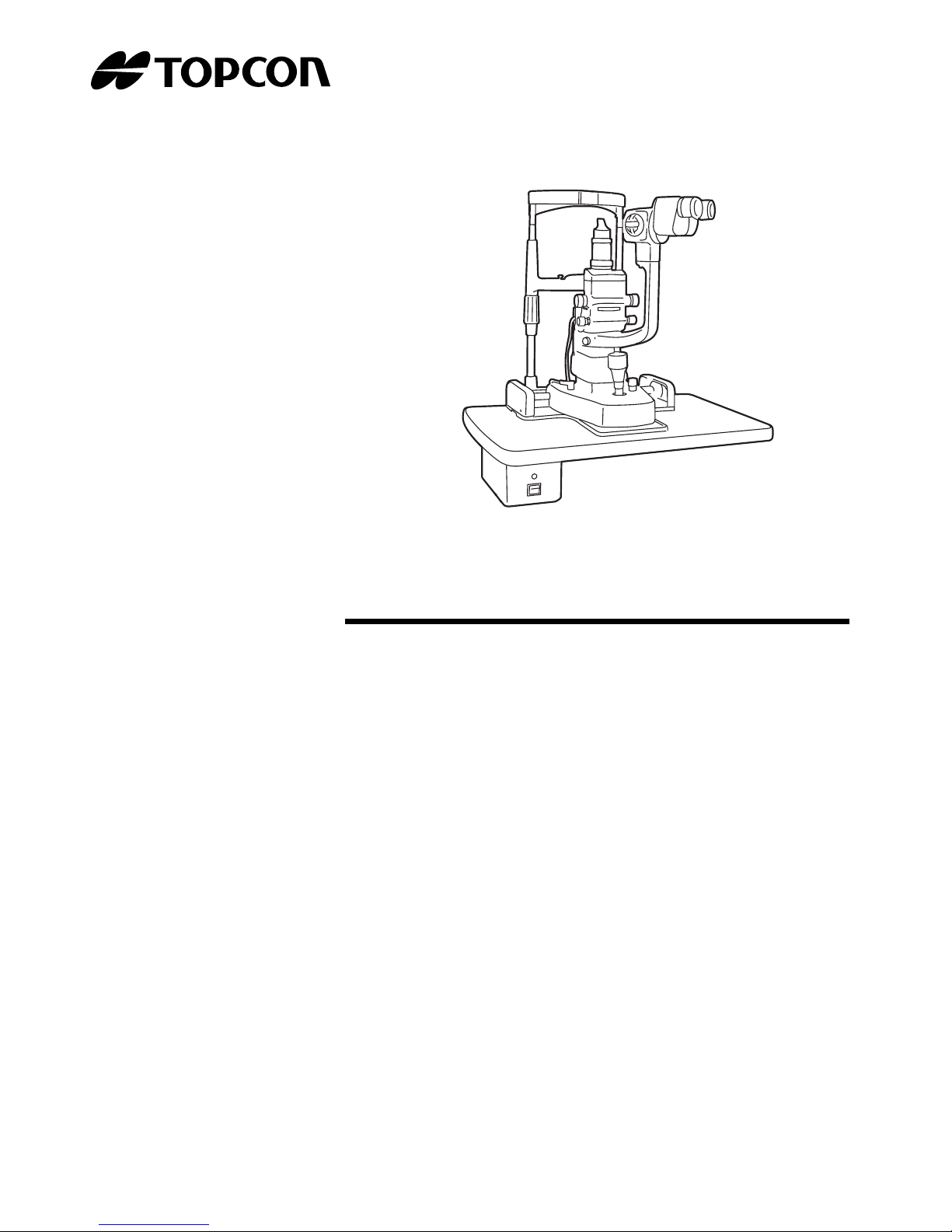
SLIT LAMP
SL-D2
SL-D4
SL-D4Z
Page 2

1
INTRODUCTION
Thank you for purchasing the Slit Lamp SL-D2/SL-D4/SL-D4Z.
This slit lamp is used for enlargement in the observation of eyeballs and other parts.
This instrument has the following features:
• Smooth operation
• Eye ground observation/recording with natural, clear colours
• Function for automatic right/left eye detection, useful for digital recording
• Apochromatic optical system to realize natural colour and high resolution
• Robustness and durability
• SL-D4Z makes continuous observation by manual zoom microscope possible.
This Instruction Manual gives a summary of the basic operation, troubleshooting, checking,
maintenance and cleaning of Slit Lamps SL-D2, SL-D4 and SL-D4Z.
To ensure the best use of the instrument, read "Displays for Safe Use" and "Safety Precautions".
Keep this Instruction Manual with the instrument for future reference.
PRECAUTIONS
WORKING ENVIRONMENT
Temperature: 10°C-40°C
Humidity: 30-75% (no dewing)
Atmospheric Pressure: 700hPa-1,060hPa
STORAGE METHOD
1. Environmental Conditions
Temperature: 10°C-40°C
Humidity: 30-75% (no dewing)
Atmospheric Pressure:700hPa-1,060hPa
2. Place of Storage
(1) Protected from water splashes
(2) Protected from adverse effects caused by atmospheric pressure, temperature,
moisture,
ventilation, sunlight, dust, salt content, sulphur, etc.
(3) Stable, without slopes, and protected from vibrations, shocks (including
transportation), etc.
(4) Free of chemicals and gases
PERMISSIBLE ENVIRONMENTAL CONDITIONS FOR TRANSPORT AND STORAGE
Temperature: -20°C-50°C
Page 3

2
Humidity: 10-95%
Page 4

3
MAINTENANCE AND CHECKS
1. Regularly maintain and check equipment and parts.
2. When using equipment for the first time in a while, check in advance that everything is
operating as it should.
3. Keep the objective lens free of fingerprints and dust.
4. When not is use, protect the instrument with the dust cover.
5. If the objective lens is stained, clean it in accordance with the information under “Cleaning
Lenses and Prisms” in the Instruction Manual.
Page 5
4
DISPLAYS FOR SAFE USE
In order to ensure the safe use of the product and to prevent danger to the operator and others, or
damage to property, important warnings are placed on the product and described in the instruction
manual.
All users are recommended to take note of the meaning of the following displays and icons before
reading the "Safety Precautions" and text.
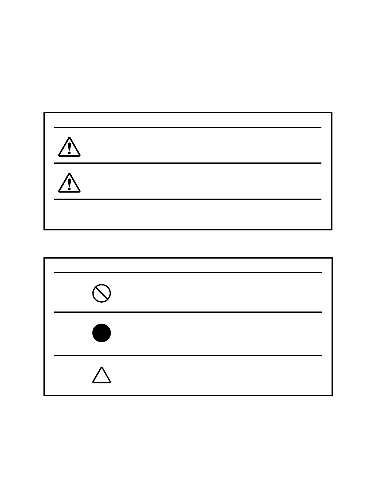
DISPLAYS
DISPLAY MEANING
Ignoring or disregarding this notice could lead
to death or serious injury.
Ignoring or disregarding this display could
lead to personal injury or physical damage.
• Injury refers to cuts, bruises, sprains, fractures, burns, electric shocks, etc.
• Physical damage refers to damage to buildings, equipment or furniture.
ICONS
ICONS MEANING
This indicates Prohibition.
Specific content is expressed via words or icons, with
words either inserted in the icon itself or located next to
the icon.
This indicates Mandatory Action.
Specific content is expressed via words or icons, with
words either inserted in the icon itself or located next to
the icon.
This icon indicates Hazard Alert (Warning).
Specific content is expressed via words or icons, with
words either inserted in the icon itself or located next to
the icon.
WARNING
CAUTION
Page 6
5
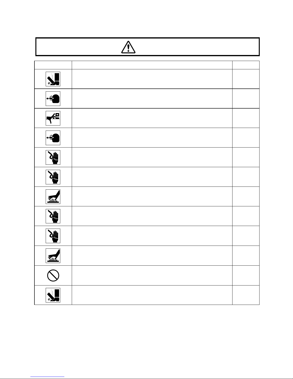
SAFETY PRECAUTIONS
Icons Prevention item Page
“To prevent units from falling during use and movement, secure
each unit.”
15
To avoid injury to the patient’s eye and nose, pay particular
attention while operating the instrument body.
29
To prevent fingers from being caught between moving parts,
beware of the moving parts while operating the main body.
29
To avoid causing the patient pain and damage to the patient’s eye,
do not make the illumination too bright.
30
To avoid electric shocks, do not attempt overhauling, rebuilding or
repairs. Contact your dealer for repairs.
39
When replacing the lamp, switch off the power supply and remove
the power cable to avoid electric shocks.
34
If you replace the lamp immediately after switching it off, beware of
high temperatures: they could cause burns.
34
When replacing fuses, first switch off the power supply and remove
the power cable to avoid electric shocks.
36
Before carrying out daily maintenance, remove the power cable (to
avoid electric shocks) and wait until the body has cooled down (to
avoid burns).
37
To prevent burns, do not touch parts inside the lamp cover house
during operation and immediately after switching off the power
supply.
37
The base contains strong springs. Do not attempt to disassemble
or burn the base, as the springs could cause injury by shooting out
of it.
38
To prevent items from falling during use and movement, attach
optional accessories securely.
40
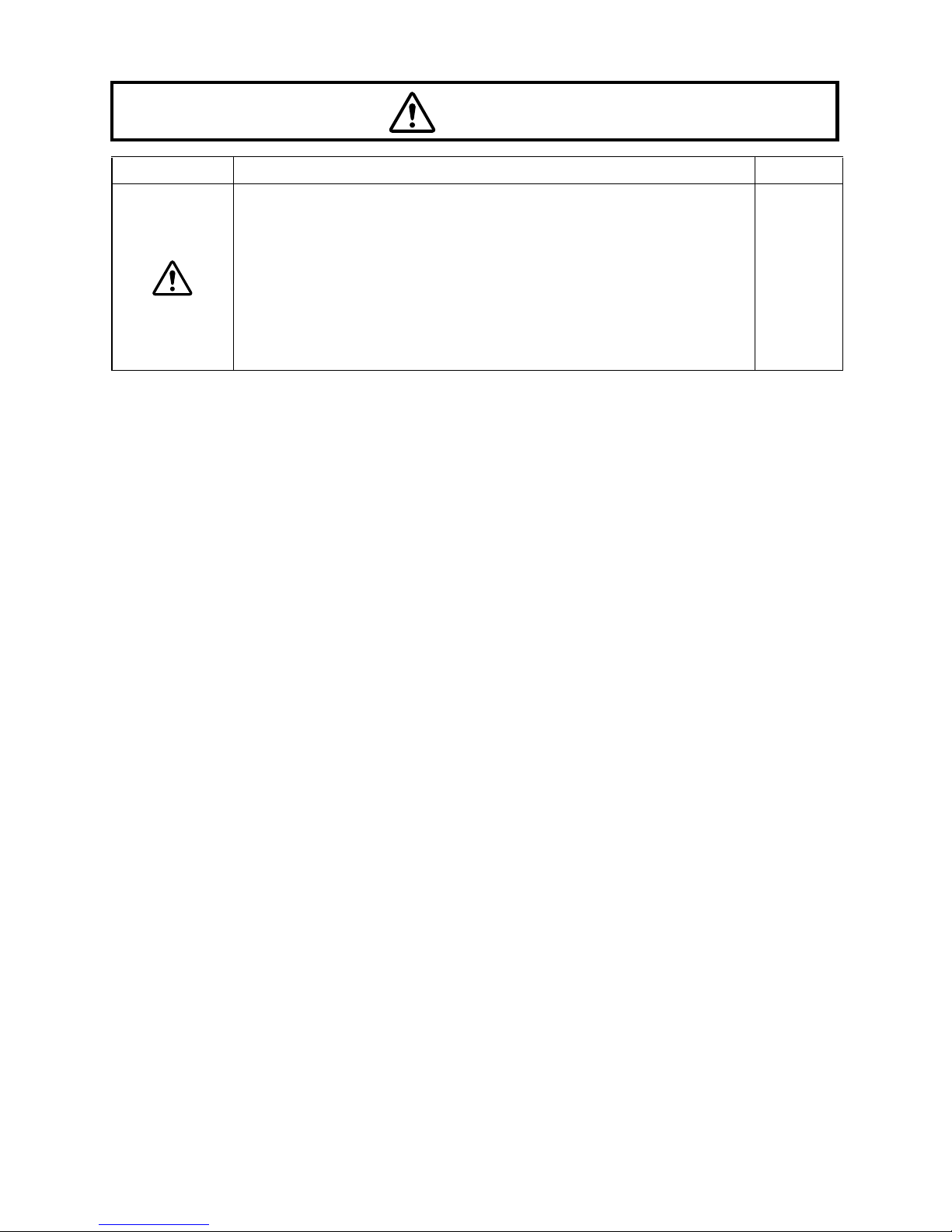
CAUTION
Page 7
6
This instrument has been tested (with 120V/230V) and found to
comply with IEC60601-1-2: 2001.
This instrument radiates radio frequency energy within standards
and may affect other devices in the vicinity.
If you have discovered that turning the instrument on or off affects
other devices, we recommend you change its position, keep it at a
proper distance from other devices, or change the outlet.
If you have any questions, please contact the dealer who supplied
the equipment.
––
Icons Prevention item Page
CAUTION
Page 8

7
MAINTENANCE
USER MAINTENANCE
To ensure the safe operation of the instrument, all maintenance should be carried out by an
authorized service engineer, unless otherwise specified in this manual.
For details about maintenance, read the description of this manual.
REPLACING THE ILLUMINATION LAMP
The illumination lamp can be replaced if necessary. For specific instructions, see page 34.
REPLACING THE FUSE
Fuses on the primary side can be replaced, if necessary. For specific instructions, see
page 36.
ESCAPE CLAUSE
• TOPCON shall take no responsibility for damage due to fire, earthquakes, actions by a third
party or other accidents, or the negligence and misuse of the user and use under unusual
conditions.
• TOPCON shall take no responsibility for damage derived from the inability to use this
equipment, such as a loss of business profit and suspension of business.
• TOPCON shall take no responsibility for damage caused by operations other than those
described in this Instruction Manual.
• Diagnoses made are the responsibility of qualified doctors and TOPCON shall take no
responsibility for the results of such diagnoses.
Page 9

8
WARNING INDICATIONS AND POSITIONS
To ensure safety, warning labels are provided on the instrument body.
Abide by these warning instructions. If any of the following labels are missing, contact your
dealer or TOPCON (see the back cover).
CAUTION
• To prevent electric shocks, switch off the power supply and remove the
power cable before replacing the lamp.
• Do not replace the lamp immediately after switching it off: the high
temperatures could cause burns.
CAUTION
• To prevent electric shocks, turn off the power switch and remove the
power cable before replacing fuses.
• Use the specified fuse.
CAUTION
When operating the base unit, please
note the following:
• Beware of catching fingers in the
moving parts.
• Avoid hitting the patient’s eyes or
nose.
Page 10

9
CONTENTS
INTRODUCTION .......................................................................................1
DISPLAYS FOR SAFE USE......................................................................4
SAFETY PRECAUTIONS..........................................................................5
MAINTENANCE.........................................................................................7
USER MAINTENANCE..............................................................................7
ESCAPE CLAUSE.....................................................................................7
WARNING INDICATIONS AND POSITIONS ............................................8
CONFIGURATION
NAMES OF MAIN BODY COMPONENTS ..............................................11
STANDARD ACCESSORIES ..................................................................12
COMPONENTS
COMPONENTS .......................................................................................14
ASSEMBLY PROCEDURE
SECURING THE INSTRUMENT TYPE TABLE TOP..............................15
SECURING THE UNIT TYPE TABLE TOP .............................................16
SECURING THE PATIENT GRIP PG-1 (OPTIONAL ACCESSORY) .....16
SECURING THE CHINREST BASE PLATE ...........................................17
SECURING THE BASE UNIT AND RAIL COVER ..................................17
SECURING THE BINOCULAR TUBES...................................................18
SECURING THE ILLUMINATION UNIT ..................................................18
CONNECTING AND SECURING CABLES .............................................20
FITTING THE CHINREST TISSUE .........................................................20
FITTING THE CAP ..................................................................................21
SECURING THE TONOMETER MOUNT (OPTIONAL ACCESSORY) ..21
COUNTER-BALANCING THE VERTICAL MOVEMENT ........................23
PREPARATIONS
POWERING ON ......................................................................................25
ADJUSTING THE DIOPTER AND PUPILLARY DISTANCE (PD) ..........25
OPERATION PROCEDURES
FIXING THE PATIENT’S FACE AND FIXATION ....................................28
OPERATING THE MICROSCOPE UNIT ................................................28
OPERATING THE BASE AND FOCUSING ............................................29
OPERATING THE ILLUMINATION UNIT................................................30
ENDING PROCEDURE...........................................................................32
TROUBLESHOOTING
TROUBLESHOOTING GUIDE ................................................................33
SPECIFICATIONS AND PERFORMANCE
SPECIFICATION AND PERFORMANCE................................................34
ELECTROMAGNETIC COMPATIBILITY ................................................35
Page 11

10
ELECTRIC RATING ................................................................................35
SYSTEM CLASSIFICATION ...................................................................35
PURPOSES OF USE ..............................................................................35
OPERATION PRINCIPLES .....................................................................35
SYSTEM CONFIGURATION...................................................................36
SHAPE OF PLUG....................................................................................37
SYMBOL..................................................................................................37
MAINTENANCE AND CHECKS
PERIODIC MAINTENANCE ....................................................................38
DAILY MAINTENANCE ...........................................................................38
ORDERING CONSUMABLES.................................................................38
REPLACING ILLUMINATION LAMPS.....................................................39
REPLACING FUSES ...............................................................................41
RESTOCKING CHINREST TISSUE........................................................41
MAINTENANCE PROCEDURE...............................................................42
CLEANING REMOVABLE PARTS ..........................................................42
CLEANING LENSES AND PRISMS........................................................42
CLEANING THE SLIDING PLATE, RAIL AND WHEEL SHAFT .............43
DISPOSING OF THE PRODUCT............................................................43
OPTIONAL ACCESSORIES
DIGITAL CAMERA UNIT DC-1................................................................44
STILL CAMERA ATTACHMENT SR-53 ..................................................44
BEAM SPLITTER ....................................................................................45
TV RELAY LENS .....................................................................................45
TV RELAY LENS TL-54...........................................................................46
TV RELAY LENS TL-55...........................................................................46
TV ATTACHMENT TL-56 ........................................................................46
TV ATTACHMENT TL-57 ........................................................................47
BACKGROUND ILLUMINATION BG2-GN ..............................................47
OBSERVATION TUBE ............................................................................47
FIXATION TARGET.................................................................................47
12.5X MEASURING EYEPIECE..............................................................48
20X EYEPIECE .......................................................................................48
APPLANATION TONOMETER................................................................48
HRUBY LENS..........................................................................................48
PARALLEL BINOCULAR TUBE PB-2 .....................................................49
YELLOW FILTER UNIT ...........................................................................49
AUXILIARY SPRING SO-AS 0, 1, 2, 3 ....................................................49
PATIENT GRIP PG-1 ..............................................................................49
ADAPT COVER SO-AC3, 4, 5.................................................................49
Page 12
11
CONFIGURATION
CONFIGURATION
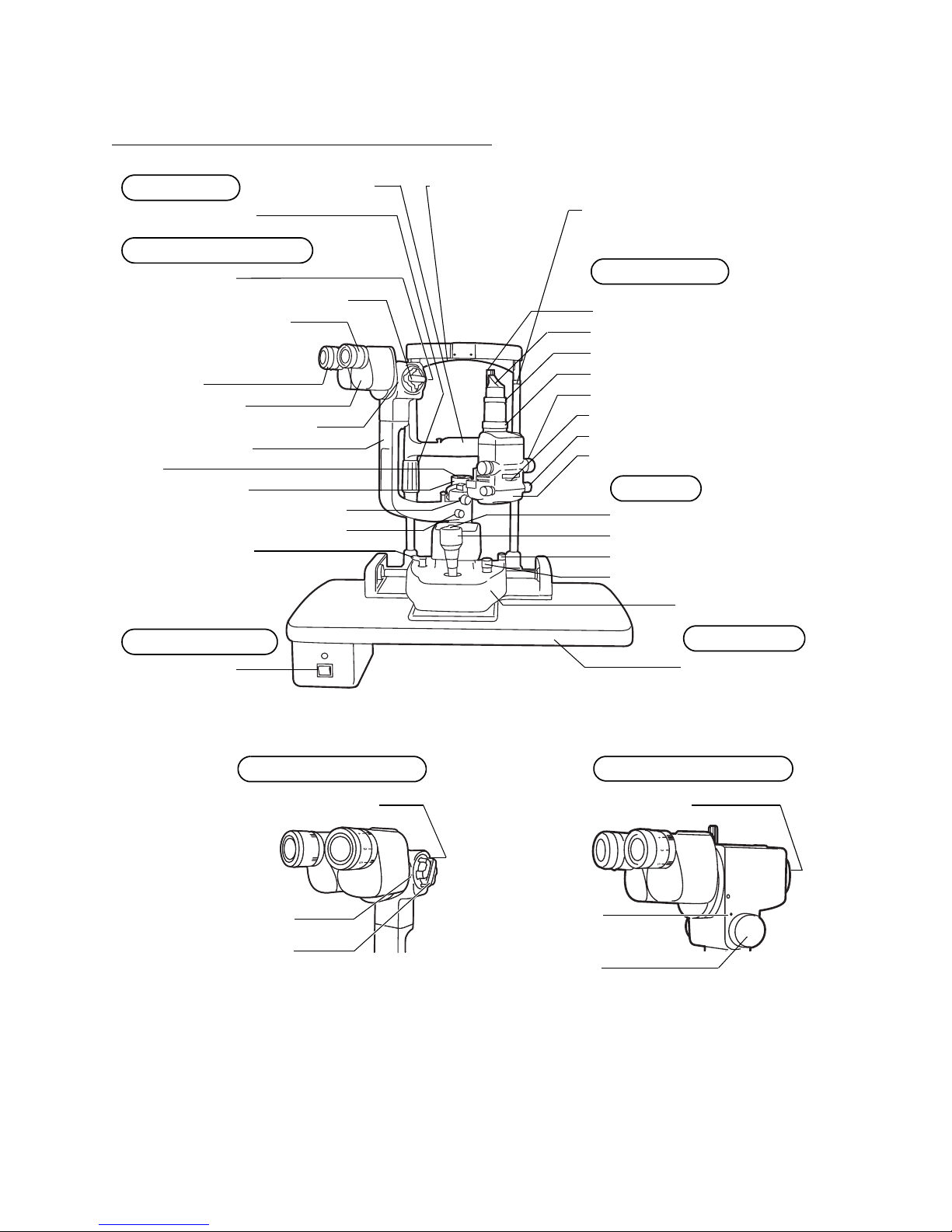
NAMES OF MAIN BODY COMPONENTS
• A model without diffusor (2) is also available.
• A model without table unit (3) is also available.
Chinrest unit
Chinrest
Chinrest adjuster
SL-D2 Microscope unit
Objective lens
Forehead rest
Canthus marker
Magnification selector handle
Diopter adjusting ring
Eyepiece
Binocular tubes
Magnification index mark
Microscope arm
Cap
Illumination arm
Illumination arm locking knob
Microscope arm locking knob
Base relay cable
Power supply unit
Power switch
Illumination unit
Prism
Slit scanning ring
Slit rotation ring
Slit width control knob
Filter selector wheel
Aperture/slit length control knob
Lamp house cover
Base Unit
Photo switch
Control lever
Base locking knob
Brightness adjustment knob
Base
Table unit (3)
Ta bl e
Diffusor (2)
SL-D4 Microscope unit SL-D4Z Microscope unit
Magnification
index mark
Magnification
selector handle
Magnification
selector handle
Magnification
index mark
Objective lensObjective lens
Page 13
12
CONFIGURATION
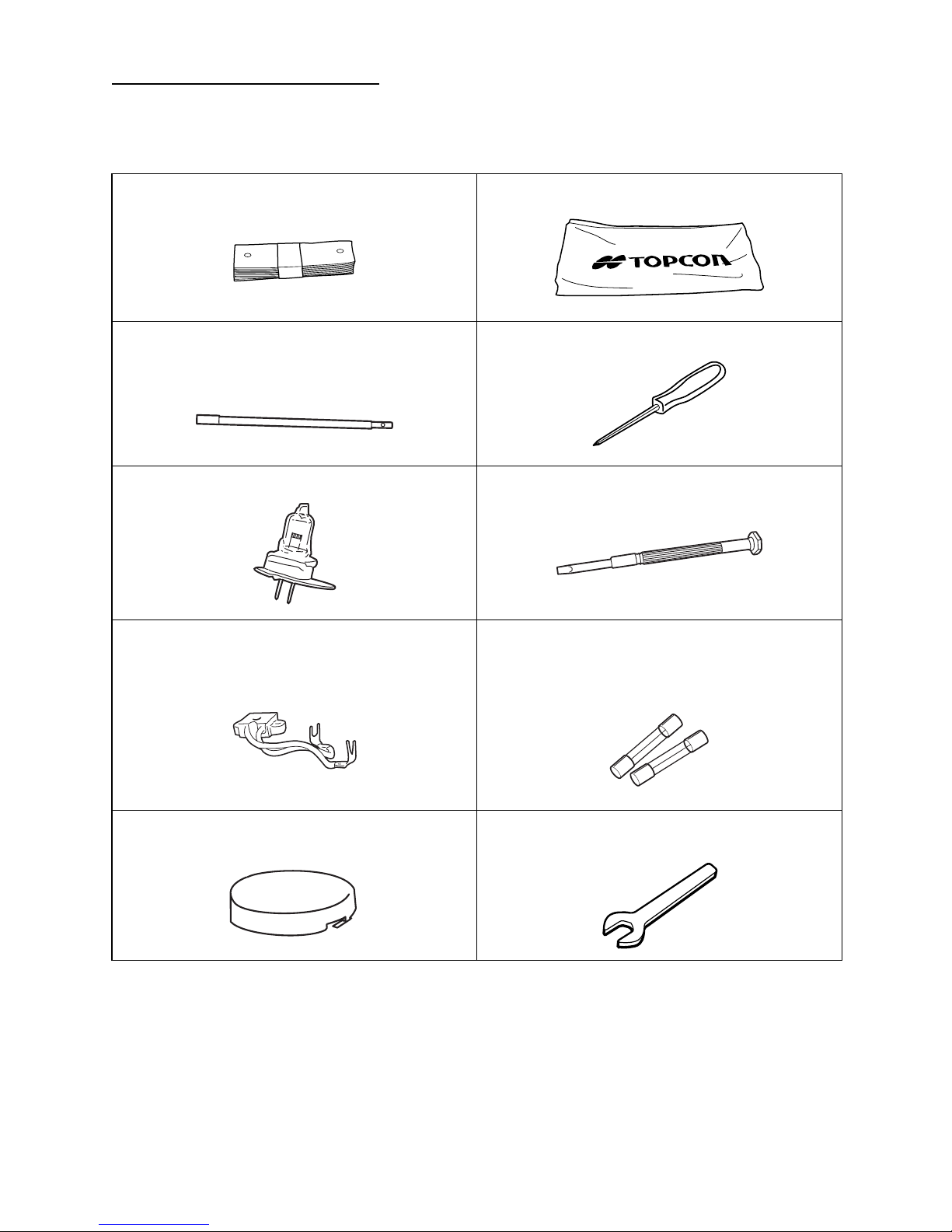
STANDARD ACCESSORIES
Make sure that all the following standard accessories are included.
Figures in parentheses are the quantities.
Chinrest tissue (1) Dust cover (1)
Test rod (1)
(This is not always included with the standard
specifications.)
Crosshead screwdriver (1)
Spare illumination lamp (1) Screwdriver (1)
Spare socket (1) Spare fuse (2)
(Quantity may differ, depending on the
specification, or this item may not be included
in standard accessories.)
Cap (1) Spanner (1)
(for instrument type table top only)
Page 14
13
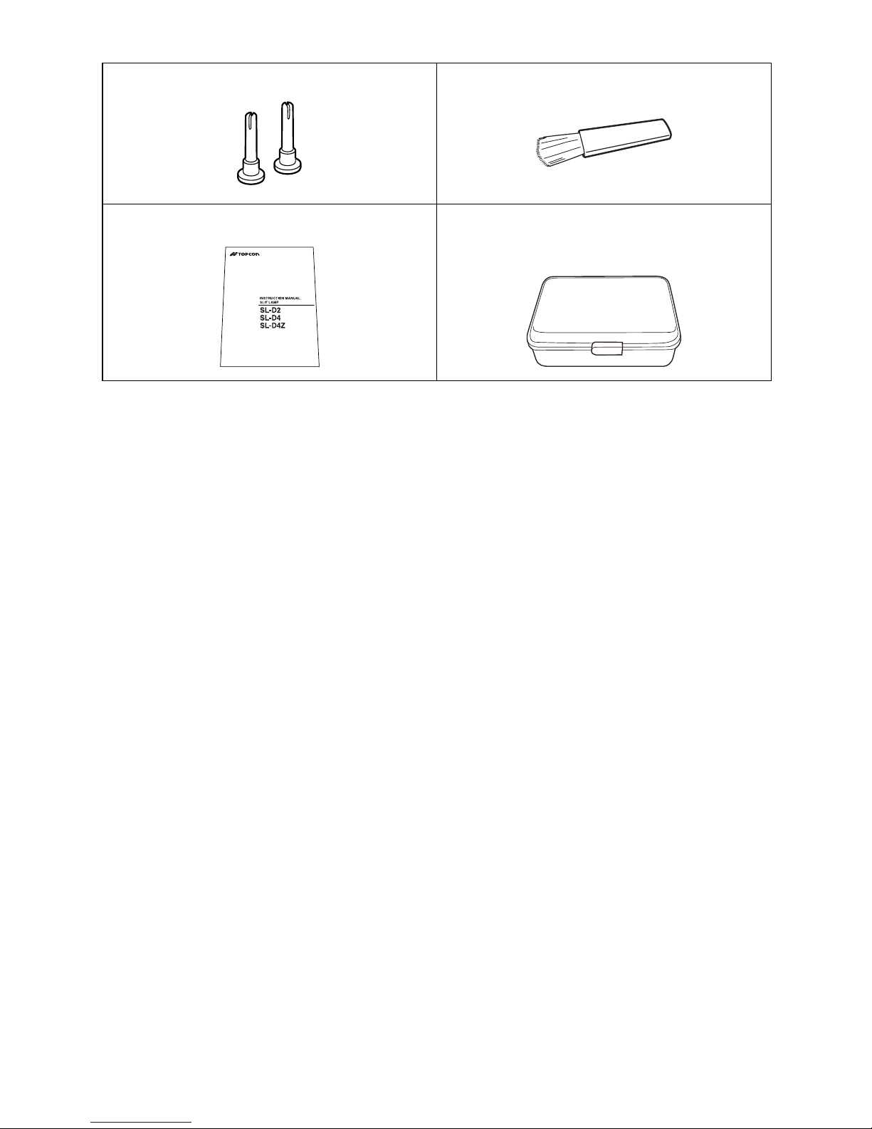
CONFIGURATION
For optional accessories, see “Optional Accessories” on page 40.
Spare chinrest tissue pin (2) Cleaning brush (1)
Instruction Manual (1) Accessory case (1)
(This is not always included with the standard
specifications.)
Page 15
14
COMPONENTS
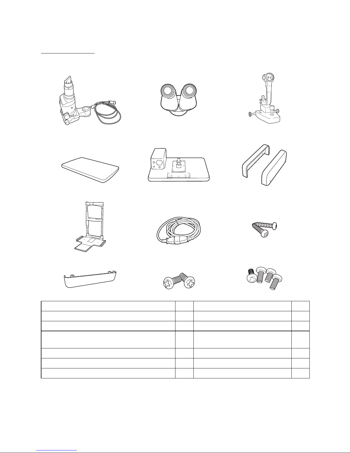
COMPONENTS
COMPONENTS
* (4) or (4)’ table top is not included, depending on the specifications.
(6) Depending on the specifications, chinrest might not be included.
(1) Illumination unit (2) Binocular tubes (3) Base unit
* The illustration shows the SL-D2 type.
(4) Instrument type table top
(w/power supply)*
(4)’ Unit type table top* (5) Rail cover
(6) Chinrest base unit* (7) Power cable (8) Setscrew
(for chinrest base unit)
(9) Cable cover (10) Cable cover fixing
screw
(11) Rail cover fixing screw
Article name Qty Article name Qty
(1) Illumination unit 1 (6) Chinrest base unit 1
(2) Binocular tubes 1 (7) Power cable 1
(3) Base unit 1
(8) Setscrew
(for chinrest base unit)
2
(4)
Instrument type table top (w/power supply)*
1(9) Cable cover 1
or (4)’ Unit type table top 1 (10) Cable cover fixing screw 2
(5) Rail cover 2 (11) Rail cover fixing screw 4
Page 16
15
ASSEMBLY PROCEDURE
ASSEMBLY PROCEDURE
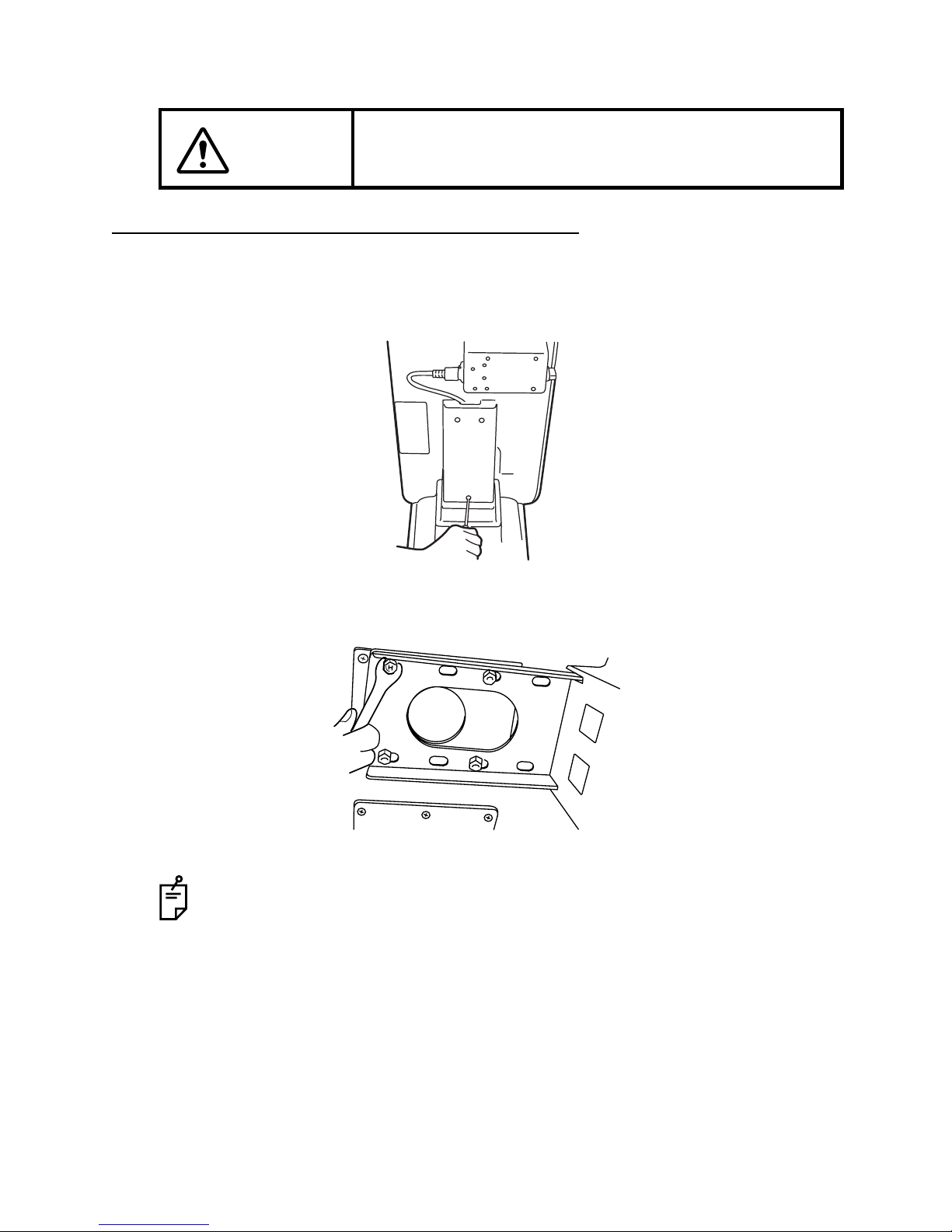
SECURING THE INSTRUMENT TYPE TABLE TOP
SECURING ON AUTOMATIC INSTRUMENT TABLE AIT-20/AIT-15
1 Remove the cover of the instrument table. Remove the 3 screws of the cover (AIT-20 only:
For details, refer to the instruction manual of AIT-20.)
2 Place the tabletop on the instrument table, and fasten it with the 4 bolts attached to the
instrument table. To reverse the direction of the instrument table, remove the power supply
from the bottom of the table top and fit it on the opposite side.
CAUTION
To prevent units from falling during use and movement, secure
each unit.
Connect the power cable to the table outlet and power supply of the instrument
table. Place the excess cable inside the cover, and fasten the cover.
Page 17
16
ASSEMBLY PROCEDURE
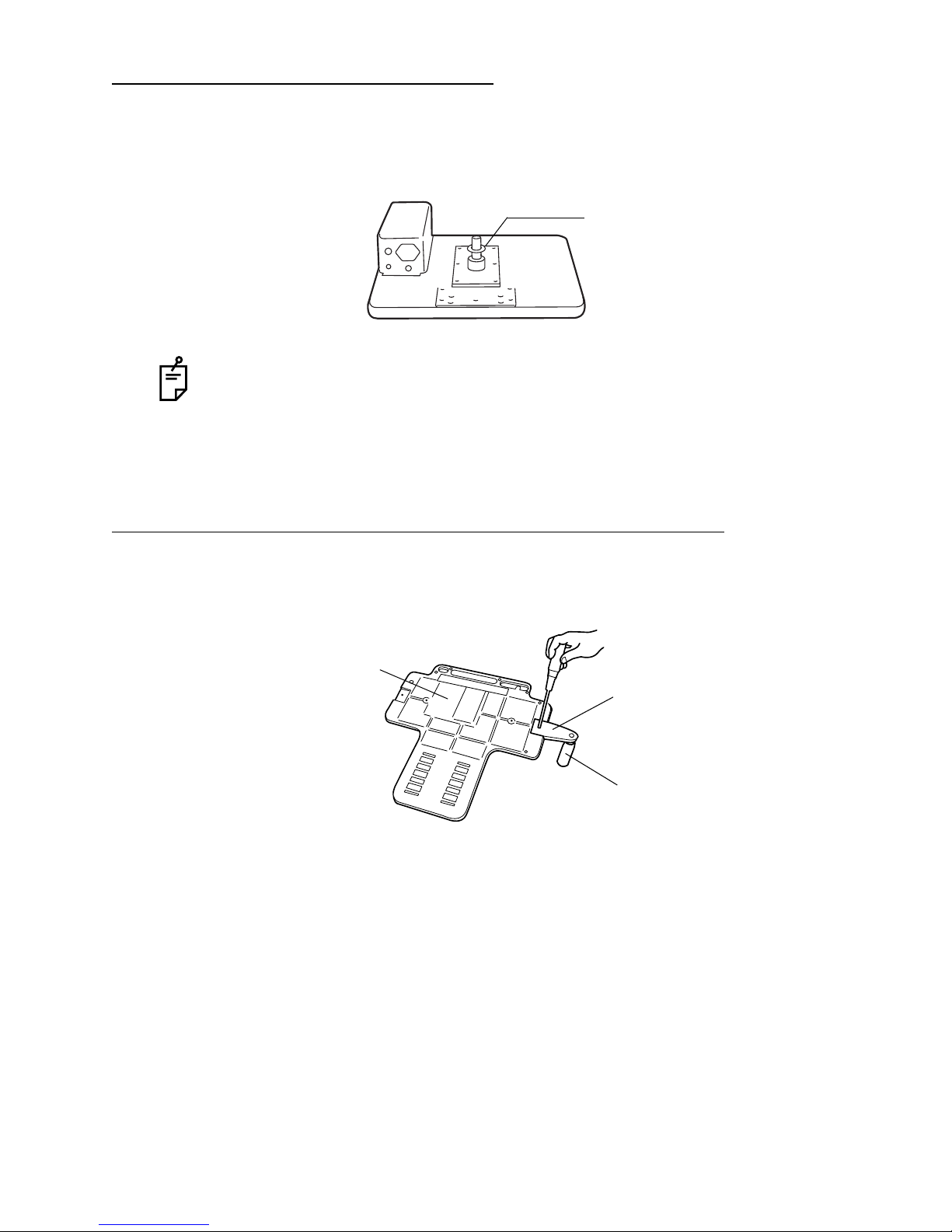
SECURING THE UNIT TYPE TABLE TOP
1 Remove the plastic washer from the unit type table top; this washer is taped to the shaft
assembly.
2 Insert the plastic washer and the shaft together into the cavity for the ophthalmic unit arm.
SECURING THE PATIENT GRIP PG-1 (OPTIONAL ACCESSORY)
1 Align the patient grip with the groove in the back of the chinrest base unit.
2 Screw the patient grip on firmly.
In the unit type table top, the power supply is fitted so that the ophthalmic unit is on
the right-hand side. When attaching the ophthalmic unit on the left-hand side,
remove the power supply and reattach it to the right-hand side (with 4 screws).
Washer
Patient grip
Chinrest base plate
Grip
Page 18

17
ASSEMBLY PROCEDURE
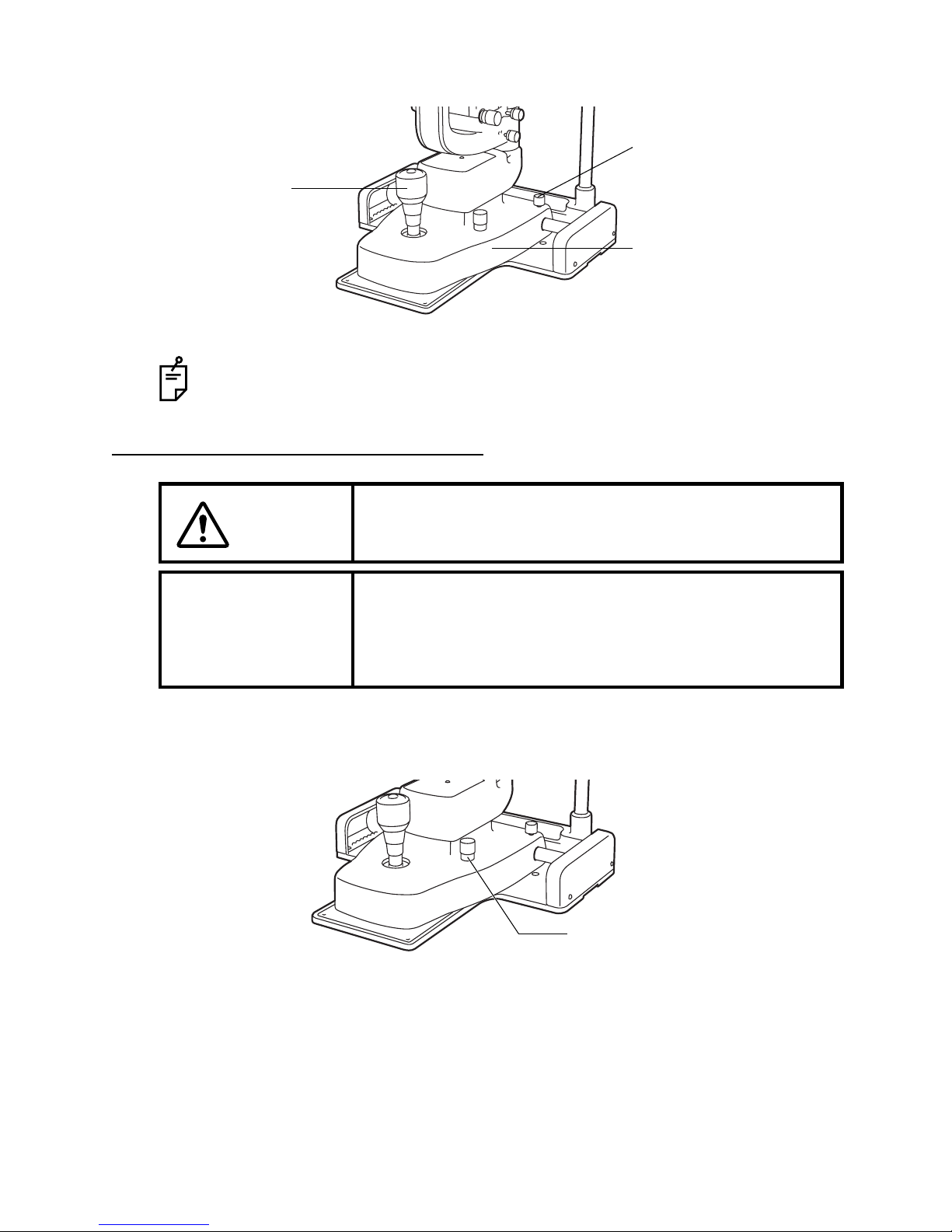
SECURING THE CHINREST BASE PLATE
1 Secure the chinrest base plate to the unit type table top with 2 screws (8).
SECURING THE BASE UNIT AND RAIL COVER
1 Align the wheel of the base unit with the rail of the chinrest base plate.
2 Fasten the rail covers with 4 screws (11): (2 screws each on the right and left sides).
Chinrest base plate
Rail cover
Page 19

18
ASSEMBLY PROCEDURE
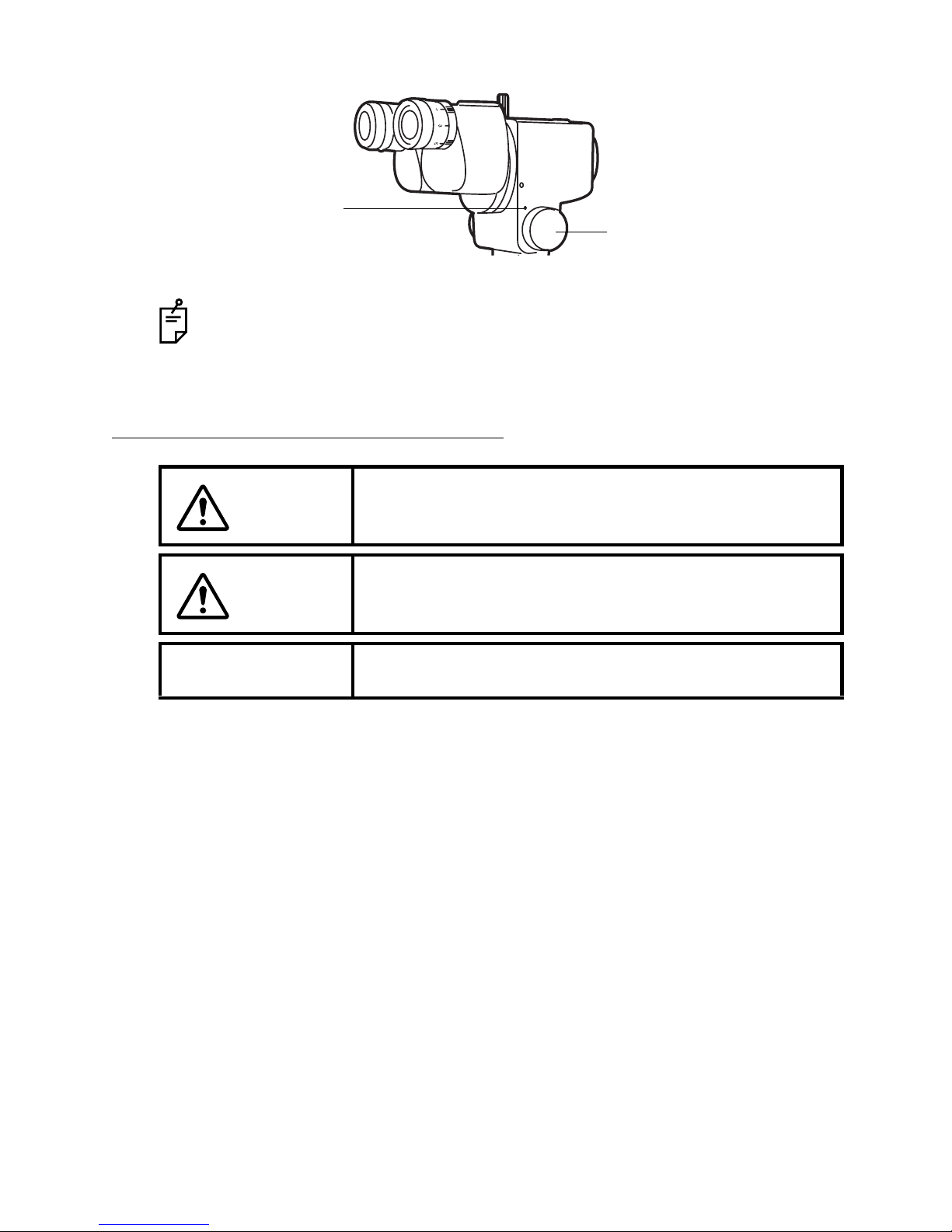
SECURING THE BINOCULAR TUBES
1 Align the pin of the microscope unit with the groove on the binocular tubes, and fasten the
fixing screw.
SECURING THE ILLUMINATION UNIT
1 Loosen the microscope arm locking knob of the base unit. Manually turn the shaft and tilt
the guide rod-shaft index 30-60°. Now refasten the microscope arm locking knob.
Make sure you do not touch the lens surfaces.
Fixing screw
Microscope unit
* The illustration shows
the SL-D2 type.
30° - 60°
Page 20

19
ASSEMBLY PROCEDURE
2 Loosen the fixing screw on the outside of the fitting cavity of the illumination unit with a
screwdriver. Align indices and slowly lower the illumination unit on to the shaft of the base
unit.
3 Firmly tighten the fixing screw with a screwdriver.
While assembling the illumination unit, take care not to get your fingers caught.
To allow smooth rotation of the illumination unit, make sure you do not fasten the
screw too tightly.
Indices
Page 21
20
ASSEMBLY PROCEDURE
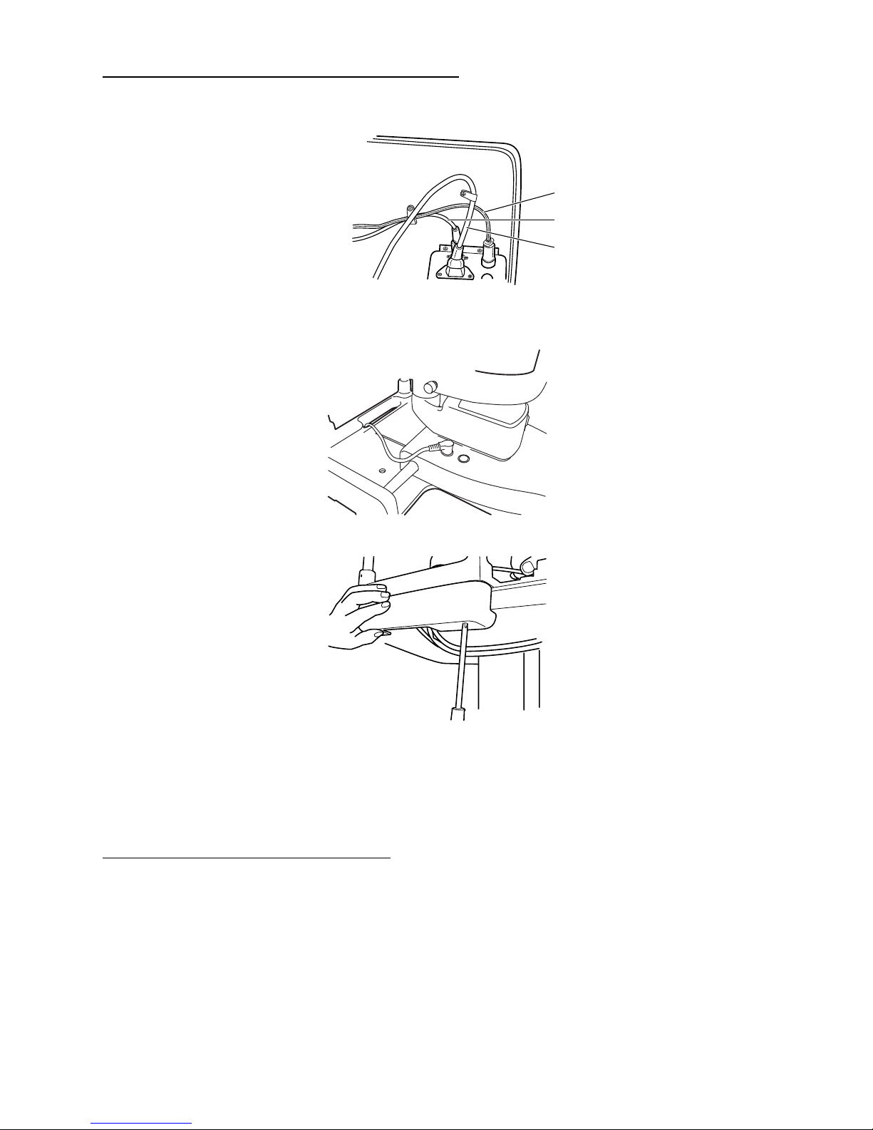
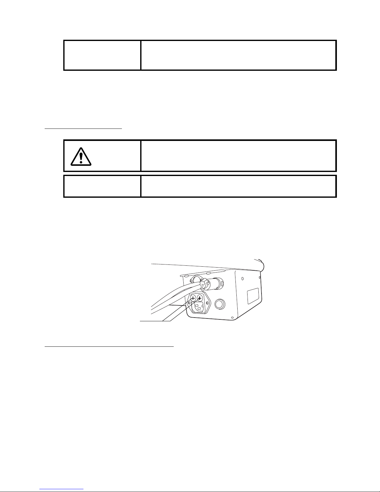
CONNECTING AND SECURING CABLES
1 Connect the cable of the illumination unit and the power cable to the power supply.
2 Pass the 5-pin connector of the metal plug connected to the power supply through the
hole of the chinrest and connect it to the base unit.
3 Fit the cable cover with 2 screws (10).
4 Pull the base unit toward the side of the operator, then lock it. Attach the cables to the
back of the table with the cable clip.
5 Move the base unit and illumination unit, and make sure there is enough cable to allow
free movement of the base unit in all directions.
FITTING THE CHINREST TISSUE
1 Remove the chinrest tissue pins.
2 Take approximately one-fifth of the pad of chinrest tissues and secure this at each end
with the pins.
Fixation cable
Illumination cable
Power cable
Page 22

21
ASSEMBLY PROCEDURE
FITTING THE CAP
1 Fit the cap to the shaft, aligning the guide rod with the groove in the cap.
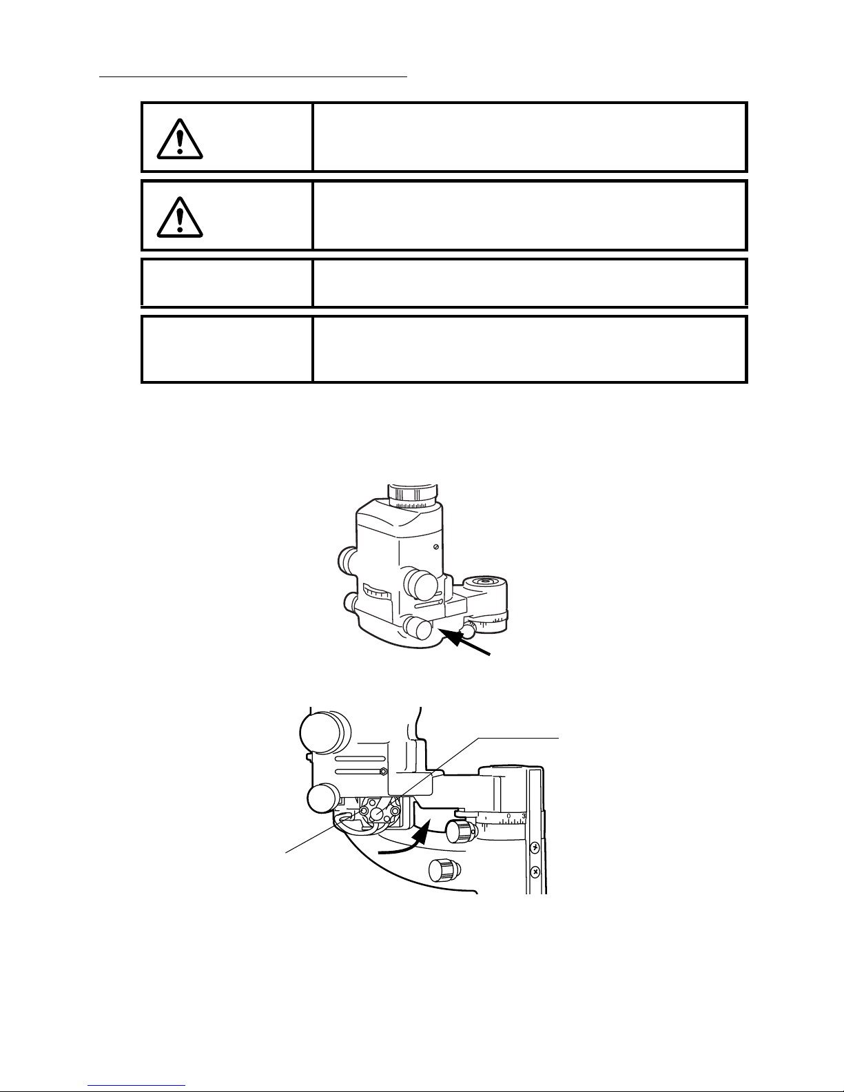
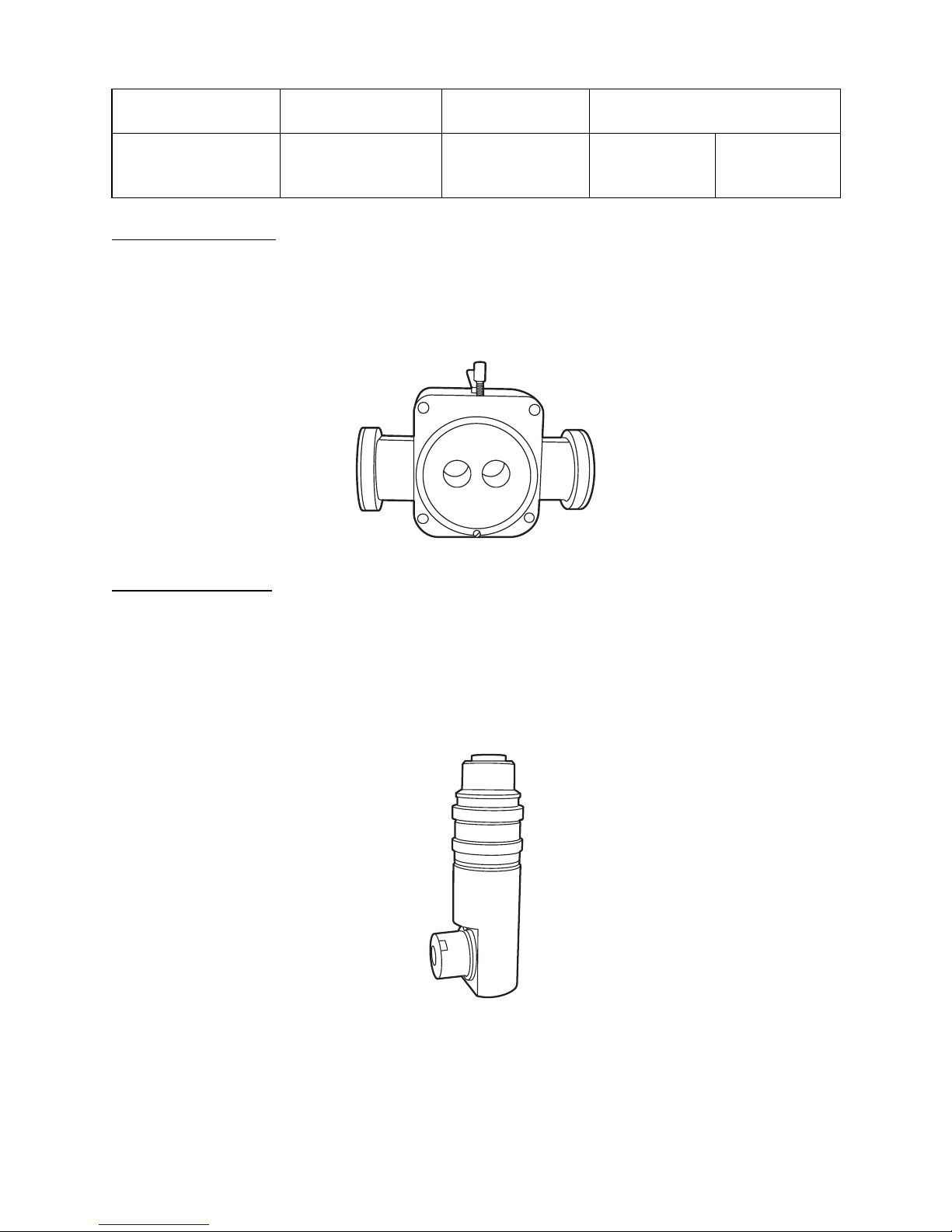
SECURING THE TONOMETER MOUNT (OPTIONAL ACCESSORY)
SO-TM1 and SO-TM2 may be included in standard accessories, depending on the
specifications.
SO-TM1
1 Align the locating pins of SO-TM1 into the holes of the SL-D2/D4 microscope, and fasten
the screw.
2 The applanation tonometer R900 type can be mounted on SO-TM1.
SO-TM2
1 Align the locating pins of SO-TM2 into the holes of the SL-D2/D4 microscope, and fasten
the fixing knob.
2 The applanation tonometer 870 type can be mounted on SO-TM2.
* Illustration shows
the SL-D2 type.
Locating pins
Screw
* Illustration shows
the SL-D2 type.
Fixing knob
Locating pins
The holes
Page 23

22
ASSEMBLY PROCEDURE
SO-TM3
1 Align the locating pins of SO-TM3 into the holes of the SL-D4Z microscope, and fasten the
two screws.
2 The applanation tonometer R900 type can be mounted on SO-TM3.
SO-TM4
1 Align the locating pins of SO-TM4 into the holes of the SL-D4Z microscope, and fasten the
two screws.
2 The applanation tonometer 870 type can be mounted on SO-TM4.
The holes
Screws
Locating pins
Locating pins
Screws
Page 24

23
ASSEMBLY PROCEDURE
COUNTER-BALANCING THE VERTICAL MOVEMENT
When you fit accessories, including the photography unit, to the main body, you may need to
adjust the vertical counter-balance movement. To do this, auxiliary springs must be fitted.
Each auxiliary spring consists of 2 identical springs.
Do not use different springs together in one set.
COUNTER-BALANCE PROCEDURE
1 Turn the control lever clockwise and raise the base to the top position, remove the centre
screw and take off the cover.
Major Combinations of Accessories and Necessary Auxiliary Springs
Accessories
Necessary auxiliary spring
Without
tonometer
With
tonometer
TV relay lens TL-55 + SONY DXC-33 (DXC-390)
None
Auxiliary
spring
SO-AS0
TV attachment TL-56 + Nikon Microsystem
Digital camera unit DC-1
TV relay lens TL-54 + JVC KY-F70
Auxiliary
spring
SO-AS0
Auxiliary
spring
SO-AS0
Beam splitter + Observation tube
Auxiliary
spring
SO-AS1
Camera attachment SR-53 + NIKON mount + FUJI FINEPIX
S2 Pro
Beam splitter + TV relay lens (1/2C) + JVC KY-F70
Auxiliary
spring
SO-AS2
Cover
Page 25

24
ASSEMBLY PROCEDURE
2 Insert the auxiliary spring unit vertically into the auxiliary spring port, with the flange face
turned upwards. (Make sure that the spring is inserted into the groove in the bottom of the
port.)
3 Open the auxiliary spring unit with the auxiliary spring port, and lightly push the spring till
it stops. (You can use a large screwdriver, a flat sheet metal tool, a coin or something
similar to do this.)
4 With the auxiliary spring unit lightly touching the stopper, turn about 90° (in either
direction), then release. The auxiliary spring locks into the positioning groove and
assembly is complete. (To remove the auxiliary spring, lightly press it down to the stopper,
rotate it 90° and remove from the port.)
Auxiliary spring port
Page 26
25
PREPARATIONS
PREPARATIONS
POWERING ON
1 Connect the power cable.
2 Turn the POWER switch ON.
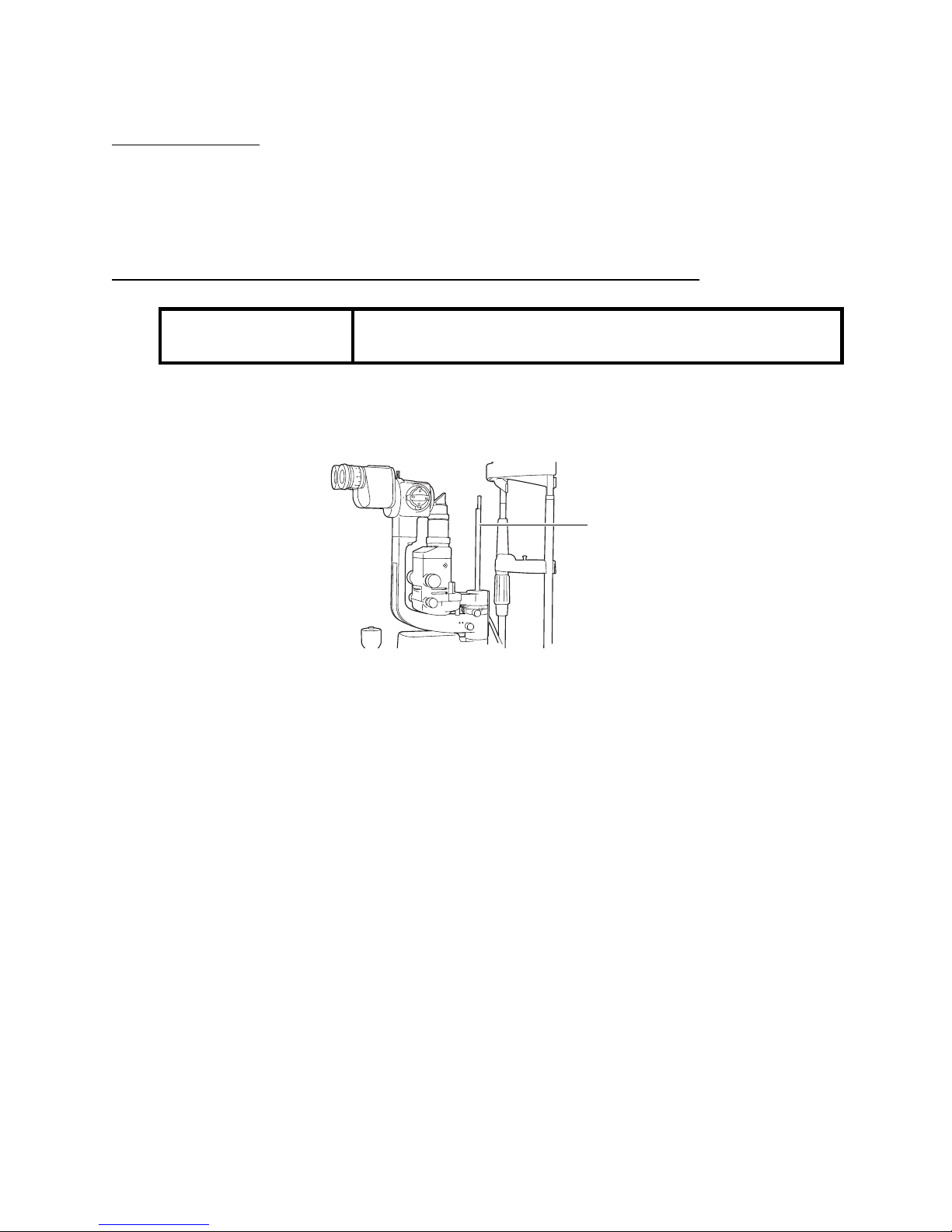
ADJUSTING THE DIOPTER AND PUPILLARY DISTANCE (PD)
If no test rod is provided, turn the diopter adjusting ring to set the diopter scale to your diopter.
1 Insert the test rod into the rotation shaft cavity, and set the black face square with the
microscope.
2 Turn the POWER switch ON and turn the brightness adjustment knob to an intermediate
position.
3 Adjust the illumination to φ 10mm by adjusting the slit adjustment knob and aperture/slit
length selector knob.
4 Turn the diopter adjusting ring of the eyepiece counter-clockwise to the end.
5 Turn the diopter adjusting ring clockwise and stop when you can clearly see the test rod.
6 Read the value on the diopter scale of the stop position. The value shows the diopter (D).
7 Repeat diopter adjustment for the eyepiece on the other side in the same way.
8 After adjusting the diopter, turn the slit adjustment knob until the slit width is about 1mm,
then check if you can see the slit image projected on the test rod clearly.
NOTICE
To ensure sharp observation of slit images, always carry out
the diopter and eye width adjustment.
Test rod
* The illustration
shows
Page 27

26
PREPARATIONS
9 While holding the prism box, look through the eyepiece with both eyes, and adjust the eye
width so that the image projected on the test rod comes together and looks threedimensional.
The eyepiece with scale may be included in the components, depending on the specifications.
1 Insert the test rod into the rotation shaft cavity, and set the black face square with the
microscope.
2 Set the eyepiece with scale to the non-dominant eye side.
3 Turn the POWER switch ON and turn the brightness adjustment knob to an intermediate
position.
4 Adjust the illumination to φ 10mm by adjusting the slit adjustment knob and aperture/slit
length selector knob.
5 Turn the diopter adjusting ring of the eyepiece with scale ( ) fully counter-clockwise.
6 Turn the diopter adjusting ring clockwise and stop when you can clearly see both the scale
( ) and the test rod.
7 Read the value on the diopter scale of the stop position. The value shows the diopter (D).
8 Set the diopter scale of the other eyepiece to the value read.
9 Set the eyepiece with scale ( ) to the dominant eye side, and adjust the diopter scale of
the dominant eye as in steps 5 and 6.
10 After adjusting the diopter, turn the slit adjustment knob until the slit width is about 1mm,
then check if the slit image projected on the test rod can be clearly seen with both right
and left eyes.
Prism box
Diopter scale
* The illustration
shows
Diopter adjusting ring
Test rod
* The illustration
shows
Page 28

27
PREPARATIONS
11 Holding the prism box, look through the eyepiece with both eyes, and adjust the pupillary
distance so that the image projected on the test rod can be seen without diplopia (double
vision), and appears to be three dimensional.
Prism box
Diopter adjusting ring
* The illustration
shows
Page 29

28
OPERATION PROCEDURES
OPERATION PROCEDURES
FIXING THE PATIENT’S FACE AND FIXATION
1 Place the patient’s chin on the chinrest with his forehead against the forehead rest.
2 Rotate the chinrest adjuster to align the patient’s eye with the canthus marker on the
chinrest frame.
OPERATING THE MICROSCOPE UNIT
Turn the magnification selector handle and set a magnification mark to the magnification index
mark.
SL-D2
SL-D4
Forehead rest
Canthus marker
Chinrest
Chinrest adjuster
Magnification index mark
Magnification selector handle
Magnification selector
handle
Magnification index mark
Page 30
29
OPERATION PROCEDURES
SL-D4Z
OPERATING THE BASE AND FOCUSING
1 For major horizontal movements, hold the control lever in the upright position and move
the entire base.
2 For fine adjustments, move the control lever in the required direction.
3 Turn the control lever clockwise to raise the base and turn it counter-clockwise to lower the
base.
For the overall magnification in conjunction with the magnification marks of the
magnification selector handle, see page 46.
CAUTION
To avoid injury to the patient’s eye and nose, pay particular
attention while operating the instrument body.
CAUTION
To prevent fingers from being caught between moving parts,
beware of the moving parts while operating the main body.
NOTICE
Do not loosen the base locking knob excessively, as this may
cause it to fall from the base.
Magnification index mark
Magnification selector handle
Page 31
30
OPERATION PROCEDURES
4 Fasten the base locking knob to fix the base.
OPERATING THE ILLUMINATION UNIT
ADJUSTING THE BRIGHTNESS
Turn the brightness adjustment knob.
You can adjust the brightness of the illumination light to your preferred illumination setting.
• Rough focusing is carried out with major movements, following steps 1 to 3.
Fine focusing is done with the microscope, following steps 2 and 3 above.
CAUTION
To avoid causing the patient pain and damage to the patient’s
eye, do not make the illumination too bright.
NOTICE
• Adjust the slit width appropriately for the purpose of
observation.
• Use the slit width scale as a guideline.
• When using the square mirror, incline the illumination unit
at least 10°.
Base locking knob
Base
Control lever
Brightness
Page 32

31
OPERATION PROCEDURES
ADJUSTING THE SLIT WIDTH
Turn the slit width control knob.
The slit width can be changed gradually between 0 and 14mm (14mm = circle).
CHANGING THE APERTURE/SLIT LENGTH
Turn the aperture/slit length selector knob.
When the slit is fully opened, 5 types of spot illumination (φ14, φ10, φ5, φ1, φ0.3mm) are
available.
The slit length can be changed gradually between 0 and 14mm.
TURNING THE SLIT
Turn the slit rotation ring.
You can change the slit image from vertical to horizontal. In this mode, you can read the slit
angle off the angle scale.
Slit width control knob
Aperture/slit length
selector knob
Slit rotation ring
Slit angle scale
Page 33

32
OPERATION PROCEDURES
SWINGING THE SLIT SIDEWAYS
Turn the slit scanning ring and swing the illumination to the right and to the left.
This provides indirect illumination, displacing the slit light from the microscope centre.
CHANGING FILTERS
Turn the filter selector wheel and select the desired filter from the 4 types.
ENDING PROCEDURE
Turn the Power switch OFF.
This function is used for scanning observation and observation with indirect
illumination.
The amber filter is used to make the eye ground clearly visible.
Slit scanning ring
Filter selector wheel
No filter
No red-free filter
White
Blue
Blue filter
Amber filter
Orange
Green
Page 34

33
MAINTENANCE AND CHECKS
MAINTENANCE AND CHECKS
PERIODIC MAINTENANCE
Before using, check the following:
• Adjust the diopter and eye width according to “Adjusting the Diopter and Pupillary Distance
(PD)” on page 25, turn the slit adjustment knob and make the slit width about 1mm: The slit
image projected on the test rod is seen clearly.
• Move the base backwards and forwards and from right to left: The base moves smoothly.
• Component parts, including the eyepiece unit, are fitted in place.
• The chinrest base is fitted securely to the table.
• Cables and plugs are connected firmly.
DAILY MAINTENANCE
• Dust can affect this instrument adversely. Put the dust cover over it when you are not using
it.
ORDERING CONSUMABLES
• When you order consumable items, contact your dealer or TOPCON (see the back cover)
and specify the article name, product code and quantity.
Article name Product code
Illumination lamp (D display is printed on a flange.) 447402040
Socket 408212010
Chinrest tissue 403104082
Fuse T-1A, 250V (Bel Fuse, Part No. 5TT1): 100-120V 446356003
Fuse T-0.75A, 250V (Bel Fuse, Part No. 5TT750): 220-240V 447706351
Page 35
34
MAINTENANCE AND CHECKS
REPLACING ILLUMINATION LAMPS
1 Turn the Power switch OFF.
2 Hold the lamp housing cover at the arrow position on both sides, pull it downward and
remove.
3 Pull the socket fixing lever lightly and turn it counter-clockwise.
CAUTION
When replacing the lamp, switch off the power supply and
remove the power cable to avoid electric shocks.
CAUTION
If you replace the lamp immediately after switching it off,
beware of high temperatures: they could cause burns.
NOTICE
To ensure perfect illumination, make sure that the socket flange
and notch are fitted firmly.
NOTICE
Use a soft cloth and do not touch the illumination lamp with
bare fingers. Clinging fingerprints and stains may affect
illumination.
Socket fixing lever
Lamp unit
Page 36

35
MAINTENANCE AND CHECKS
4 Pull off the socket plug.
5 Pull out the lamp unit.
6 Pull out the illumination lamp from the socket and replace a new lamp in the socket: Take
note of the socket direction.
7 Install the lamp unit and lamp house cover in reverse order.
Plug
Socket
The notch of the illumination
lamp should face the opposite
side from the cable.
Page 37
36
MAINTENANCE AND CHECKS
REPLACING SOCKETS
1 Remove the lamp following steps 1 to 4 of “Replacing Illumination Lamps”.
2 Replace the socket with a new one.
3 Install the lamp unit and lamp house cover in reverse order.
REPLACING FUSES
1 Turn the Power switch OFF and remove the power cable from the AC power source.
2 Pry the fuse holder lid with a crosshead screwdriver. The fuse comes out.
3 Replace the fuse with a new factory-authorized fuse.
4 Reinstall the fuse holder in reverse order.
RESTOCKING CHINREST TISSUE
When the supply of chinrest tissue runs out, remove the chinrest tissue pins and replace the
tissue.
NOTICE
The socket may deteriorate due to the constant heat: it should
therefore be replaced after the lamps have been changed two
or three times.
CAUTION
When replacing fuses, first switch off the power supply and
remove the power cable to avoid electric shocks.
NOTICE
Use the glass tube fuse with the rating as stated on the side of
the fuse holder.
Fuse holder
Page 38

37
MAINTENANCE AND CHECKS
MAINTENANCE PROCEDURE
CLEANING REMOVABLE PARTS
Wipe the forehead rest, the chinrest and the patient grip (if a pair of patient grips is used) with
a cloth moistened with a tepid solution of neutral kitchen detergent.
CLEANING LENSES AND PRISMS
REMOVING STAINS
1 Prepare a solution of ethyl alcohol 20% and ether 80%.
2 Remove dust from the lens and prism surfaces with the attached cleaning brush, or a
blower.
3 Using clean gauze, lightly draw a spiral from the lens/prism centre outward.
4 If the stain remains, repeat this 2 to 3 times.
5 If stains are persistent, call your dealer or TOPCON (see the back cover).
CAUTION
Before carrying out daily maintenance, remove the power cable
(to avoid electric shocks) and wait until the body has cooled
down (to avoid burns).
CAUTION
To prevent burns, do not touch parts inside the lamp cover
house during operation and immediately after switching off the
power supply.
NOTICE
To prevent discoloration and deterioration in the chinrest,
forehead rest and other plastic parts, do not use volatile
solvents for cleaning, such as benzine, thinner, ether or
gasoline.
Wipe parts with a cloth moistened with a tepid solution of
neutral kitchen detergent.
NOTICE
To avoid damaging lens surfaces, do not use tweezers or
similar equipment to hold the gauze.
Page 39

38
MAINTENANCE AND CHECKS
CLEANING THE SLIDING PLATE, RAIL AND WHEEL SHAFT
1 Wipe the wheel shaft clean by moving the base to the right and to the left.
2 Raise the control lever and wipe the sliding plate clean.
DISPOSING OF THE PRODUCT
For disposal of the instrument and consumables, contact a waste disposer or call your dealer
or TOPCON (see the back cover).
NOTICE
When stained, the sliding plate and rail of the table top and the
wheel shaft of the base move less smoothly. Clean them with
a dry cloth.
CAUTION
The base contains strong springs. Do not attempt to
disassemble or burn the base, as the springs could cause
injury by shooting out of it.
Control lever
Rail
Wheel shaft
Sliding plate
Page 40

39
TROUBLESHOOTING
TROUBLESHOOTING
TROUBLESHOOTING GUIDE
If you suspect a problem, use the check list below to check the possible cause.
If the check list below does not solve the problem, or if the problem is not included in the list,
contact your dealer or TOPCON (see the back cover).
CAUTION
To avoid electric shocks, do not attempt overhauling, rebuilding
or repairs. Contact your dealer for repairs.
Check List
Problem Typical condition Check Page
Illumination lamp
does not work
Power switch is OFF. Turn Power switch ON. 25
Cable connection is
disconnected.
Connect the cable. 20
Base relay cable is switched
off.
Connect the cable. 20
Brightness adjustment knob is
at the minimum setting.
Turn up brightness selector
knob.
30
Illumination lamp is broken.
Replace it with a new
illumination lamp.
34
Socket is off. Insert the socket. 34
Socket has deteriorated. Replace it with a new socket. 36
Illumination field is
not uniform/is
shady/is dark
Aperture/slit length selector
knob is not fastened.
Click the aperture/slit length
selector knob into a fixed
position.
31
Filter selector lever is not
clicked.
Click the filter selector lever in
place.
32
Illumination lamp is not fitted in
place.
Fit the illumination lamp in the
socket.
34
Fuse blows
Rated capacity of fuse is
incorrect.
Use an approved fuse with the
correct rating.
33, 36
Fixation target
(optional) does not
work
The plug above chinrest is off. Insert the plug. ––
Fixation cable is off Insert the cable. 20
Page 41

40
OPTIONAL ACCESSORIES
OPTIONAL ACCESSORIES
TOPCON Slit Lamp SL-D2/SL-D4/SL-D4Z has the following optional accessories.
For enquiries, please contact your dealer or TOPCON (see the back cover).
• For details, please refer to the instruction manual of each product.
DIGITAL CAMERA UNIT DC-1
FEATURES
• A digital camera combined with a slit lamp.
• Cables are wired inside the arm and do not interfere with instrument operation.
• Recordable with Compact flash card.
• Connectable with the IMAGEnet
STILL CAMERA ATTACHMENT SR-53
FEATURES
• Can be connected to a marketed camera for easy photography.
• The beam splitter division ratio is TV 50%: patient 50%.
CAUTION
To prevent items from falling during use and movement, attach
optional accessories securely.
Page 42
41
OPTIONAL ACCESSORIES
CONNECTABLE CAMERA
BEAM SPLITTER
FEATURES
• Used to attach the TV relay lens T-53 (w/ beam splitter type) and observation tube.
• The TV relay lens and observation tube can be attached to either side.
• The beam splitter division ratio is TV 50%: patient 50%.
TV RELAY LENS
• Three types of TV relay lens have been prepared for use with different TV camera types (C
mount 1/2 type, C mount 1/3 type and bayonet mount 1/2 type for Sony).
FEATURES
• Used with the beam splitter.
• Can connect a TV camera to carry out monitor observation and photograph still images.
Recommendation
Size of camera’s
light receiving unit
Shape of
camera mount
Attachment & TV relay lens
FUJI
FINEPIX
S-Pro Series
APS-C size NIKON F mount Still camera
attachment
SR-53
Adapter
SO-CMNF for
NIKON F
Page 43

42
OPTIONAL ACCESSORIES
TV RELAY LENS TL-54
TV RELAY LENS TL-55
• The type of TV relay lens depends on the type of TV camera to be used.
For C mount 1/2 type TV camera: TL-54
For C mount 1/3 type TV camera: TL-55
FEATURES
• Incorporated with the beam splitter.
• Can connect a TV camera to carry out monitoring observation and photograph still images.
• The beam splitter can be switched IN and OUT.
• The beam splitter division ratio is TV 50%: patient 50%.
TV ATTACHMENT TL-56
FEATURES
• Used to connect the NIKON COOLPIX series (Micro System series).
• Combined with beam splitter.
• The beam splitter division ratio is TV 50%: patient 50%.
Page 44

43
OPTIONAL ACCESSORIES
TV ATTACHMENT TL-57
• Used to connect PANASONIC GP-KS162.
• Combined with beam splitter.
• The beam splitter division ratio is TV 50%: patient 50%.
BACKGROUND ILLUMINATION BG2-GN
FEATURES
• Used for background illumination with LED light source.
• Power is supplied from the slit lamp power supply.
• Light intensity can be adjusted.
OBSERVATION TUBE
FEATURES
• Used in combination with beam splitter.
• Used for observation together with the inspector.
• Can be inclined to facilitate observation and can prevent the
main body from falling.
FIXATION TARGET
FEATURES
• Attached to the upper part of the chinrest to guide and
fixate the patient’s visual line easily.
Page 45

44
OPTIONAL ACCESSORIES
12.5X MEASURING EYEPIECE
FEATURES
• Replaces the normal eyepiece for measuring dimensions and
angles.
20X EYEPIECE
FEATURES
• Replaces the normal eyepiece for high magnification
observation.
APPLANATION TONOMETER
FEATURES
• For measuring the intraocular pressure, models R900 type
and T900 type, Haag-Streit, are available.
* The Topcon tonometer mount is required to enable use of
the applanation tonometer, as follows:
HRUBY LENS
Normally, observation is possible only up to the anterior
vitreous body due to the refractive power of the cornea and
lens. With the Hruby lens, the posterior vitreous body and
eye ground can also be observed.
APPLANATION
TONOMETER
SLIT LAMP TONOMETER
MOUNT
R900 type SL-D2/D4 SO-TM1
SL-D4Z SO-TM3
T900 type SL-D2/D4/D4Z TONOMETER
GUIDE PLATE
870 type SL-D2/D4 SO-TM2
SL-D4Z SO-TM4
Page 46

45
OPTIONAL ACCESSORIES
PARALLEL BINOCULAR TUBE PB-2
FEATURES
• Can observe a parallel view of the object.
YELLOW FILTER UNIT
FEATURES
• Combines with the blue filter prepared in the main body for
a high-contrast fluorescence observation.
• Easy filter insertion and removal.
AUXILIARY SPRING SO-AS 0, 1, 2, 3
FEATURES
• Used to counterbalance vertical movement when you attach
accessories such as a TV relay lens.
PATIENT GRIP PG-1
FEATURES
• A grip for patients to hold for comfort during diagnosis and
photographing.
• Can be attached to the chinrest base.
ADAPT COVER SO-AC3, 4, 5
FEATURES
This is used to cover gaps with the microscope arm and hide cables
when you attach accessories such as the digital camera unit DC-1 and
the still camera attachment SR-53.
SO-AC3: For SL-D4Z + DC-1/SR-53
SO-AC4: For SL-D2/D4 + DC-1/SR-53 + yellow filter unit
SO-AC5: For SL-D4Z + DC-1/SR-53 + yellow filter unit
Page 47

46
SPECIFICATIONS AND PERFORMANCE
SPECIFICATIONS AND PERFORMANCE
SPECIFICATION AND PERFORMANCE
SL-D2 SL-D4 SL-D4Z
Microscope unit
Type Galileo type
Magnification Drum, 3-step
magnification
Drum, 5-step
magnification
Manual zoom
Magnification steps 10, 16, 25 6, 10, 16, 25, 40 10, 16 and 25 w/clicks
Overall magnification (actual
vision field)
10.00 (
φ22.5mm)/
15.98 (
φ14.1mm)/
25.53 (
φ8.8mm)/
6.37 (
φ35.1mm)/
9.94 (
φ22.5mm)/
15.87 (
φ14.1mm)/
25.37 (
φ8.8mm)/
39.62 (
φ5.6mm)/
6.35 - 31.75
(
φ35.2 - φ7mm)
*10x, 16x and 25x
w/click
Eyepiece lens Magnification:12.5x
Diopter adjustment range:-5D - +3D -5D - +5D
Binocular tubes PD adjustment: 55 - 78mm
Illumination unit
Illumination field Slit width:0-14mm, can be altered gradually (14mm = circle)
Slit length:1-14mm, can be altered gradually (14mm = circle)
Aperture diameter:
φ14, 10, 5, 1, 0.3
Slit direction Can be altered gradually from vertical to horizontal
Side swing
Filter Blue filter, red-free filter, colour conversion filter, UV cut filter (normal use), IR cut filter
(normal use)
Illumination lamp 6V, 20W halogen lamp
Base unit
Forward-backward
movement
90mm
Right-left movement 100mm
Vertical movement 30mm
Fine movement forward-
backward/right-left
12mm
Chinrest unit
Vertical movement 80mm
Dimensions, Weight
Dimensions: w/Table 550mm(W)x399mm(D)x558mm(H)
w/Unit table 440mm(W)x379mm(D)x558mm(H)
w/o Table and Chinrest 329mm(W)x306mm(D)x415-445mm(H)
Weight: w/Table 17kg 17.5kg
w/Unit table 16kg 16.5kg
w/o Table and Chinrest 9.5kg 10kg
Table size 550mmx370mm
Unit Table size 440mmx350mm
Height from the table top to
patient’s eye
375mm
The specification and design of the product can be altered for improvements without prior notice.
Page 48

47
SPECIFICATIONS AND PERFORMANCE
ELECTROMAGNETIC COMPATIBILITY
This product conforms to the EMC standard (IEC60601-1-2:2001).
ELECTRIC RATING
Source voltage:100-120V, 220-240V AC, 50/60Hz
Power input: 160VA
SYSTEM CLASSIFICATION
• Type of protection against electric shocks: Type B applied part
Type B applied part is the applied part complying with the specified requirements of the
Standard IEC 60601-1 to provide protection against electric shock, particularly regarding
allowable LEAKAGE CURRENT.
• Type of protection against electric shocks: Class Ι equipment.
Class Ι equipment does not depend on basic insulation only for protection against electric
shocks. It can also be earthed; therefore, the metal parts with which one comes into contact
do not become conductive if the basic insulation fails.
• The mode of operation: continuous operation equipment.
• Degree of protection against ingress of water: IP x0
SL-D2, SL-D4 and SL-D4Z are the ordinary instruments (enclosed instrument without
protection against ingress of water).
• Methods of sterilization or disinfection recommended by the manufacturer: SL-D2, SL-D4
and SL-D4Z do not have any part to be sterilized or disinfected.
• Not AP or APG equipment.
PURPOSES OF USE
This slit lamp is used for enlargement in the observation of eyeballs and other parts.
OPERATION PRINCIPLES
Illuminates the observed part by the illumination light emitted from the illumination optical
system and allows enlargement observation by binocular stereoscopic microscope.
Page 49

48
SPECIFICATIONS AND PERFORMANCE
SYSTEM CONFIGURATION
Video Camera
1/2 C Mount
Camera
1/3 C Mount
Camera
1/2 C Mount
Camera
1/2 Screw
Mount Camera
TV
Relay Lens
Beam Splitter
Monitor
Still Video
Recorder
Printer
IMAGEnet 2000
Still Camera
Attachment
SR-53
NIKON
COOLPIX Series
(Adapter Lens)
FUJI FINEPIX
S-Pro Series
Observation
Tube
Tonometer mount
SO-TM1(SL-D2,D4)
SO-TM3(SL-D4Z)
Tonometer mount
SO-TM2(SL-D2,D4)
SO-TM4(SL-D4Z)
12.5x eyepiece lens
with measuring scale
20x eyepiece lens
Auxiliary spring
SO-AS 0, 1, 2, 3
Parallel view eyepiece
PB-2
SL-D2/SL-D4/SL-D4Z System Chart
Digital Camera Unit DC-1
Patient grip PG-1
Mount SO-CMNF
for NIKON
Adapt Cover
SO-AC3, 4, 5
TV Relay Lens
TL-54
TV Relay Lens
TL-55
TV Attachment
TL-57
TV Attachment
TL-56
Applanation Tonometer
870 type
Fixation
Target
Applanation Tonometer
R900 type
Background Illumination
BG2-GN
Applanation Tonometer T900 type
Tonometer guide plate for T900 type
Hruby lens
Optional accessories
Marketed accessories
Z
Yellow Filter Unit
Page 50

49
SPECIFICATIONS AND PERFORMANCE
SHAPE OF PLUG
SYMBOL
Country Voltage/frequency Shape of plug
Mexico 110V/50Hz Type C&E
Argentina 220V/60Hz Type A
Peru 220V/60Hz Type A
Venezuela 110V/50Hz Type C&E
Bolivia & Paraguay 220V/60Hz
Type A (Most common)
Type H (Infrequently)
Chile 220V/60Hz Type A
Colombia 110V/50Hz Type C
Brazil
220V/60Hz
127V/60Hz
Typ e A
Typ e C
Ecuador 110V/50Hz Type C&E
Symbol IEC Publication Description Description (French)
60417-5032 Alternation Current Courant alternatif
60348
Attention, consult
accompanying documents
Attention, consulter les
documents
d’accompagnement
60417-5008
Off (power: disconnection
from the mains)
Éteint (courant: coupure
avec le secteur)
60417-5007
On (power: connection of
the mains)
Allumé (courant:
raccordement sur le secteur)
60878-02-02 Type B applied part Classe B
Page 51

When youcontact us, please have the following
information about your unitat hand:
¥Machine type: SL-D2, SL-D4, SL-D4Z
¥Manufacturing No. (Displayed on the rating plate on the
left of the base.)
¥Period of Usage (i,e. the purchase date).
¥Description of Problem (as detailed as possible).
SLIT LAMP SL-D2, SL-D4, SL-D4Z
INSTRUCTION MANUAL
The 2004 version (2004.03-100TH0)
Date of issue: 5th February, 2004
Published by TOPCON CORPORATION
75-1 Hasunuma-cho, Itabashi-ku, Tokyo, 174-8580 Japan.
2004 TOPCON CORPORATION
ALL RIGHTS RESERVED
Page 52

37 West Century Road,Paramus,New Jersey 07652,U.S.A. Phone:201-261-9450 Fax:201-387-2710 www.topcon.com
TOPCON MEDICAL SYSTEMS, INC
European Representative
Essebaan 11, 2908 LJ Capelle a/d IJssel,THE NETHERLANDS Phone:010-4585077 Fax:010-4585045 www.topconeurope.com
TOPCON EUROPE B.V.
Giesserallee 31-33 D-47877 Willich GERMANY Phone:02154-8850 Fax:02154-885111 www.topcon.de Med@topcon.de
TOPCON DEUTSCHLAND G.m.b.H.
110 Provencher Avenue, Boisbriand, QC J7G 1N1 CANADA Phone:450-430-7771 Fax:450-430-6457 www.topcon.ca
TOPCON CANADA INC.
HEAD OFFICE:Frederic Mompou 5, ED. Euro 3, 08960,Sant Just Desvern Barcelona,SPAIN Phone:93-4734057 Fax:93-4733932 www.topconesp.com
MADRID OFFICE:Avenida Burgos, 16E,1°28036,Madrid,SPAIN Phone:91-302-4129 Fax:91-383-3890
TOPCON ESPANA S.A.
Neongatan 2 S-43151 Molndal, SWEDEN Phone:031-7109200 Fax:031-7109249 info@topcon.se
TOPCON SCANDINAVIA A.B.
Topcon House,Kennet Side,Bone Lane,Newbury,Berkshire RG14 5PX United Kingdom Phone:01635-551120 Fax:01635-551170
TOPCON ( GREAT BRITAIN ) LTD.
Blk 192 Pandan Loop, #07-01 Pantech Industrial Complex, SINGAPORE 128381 Phone:62780222 Fax:62733540 www.topcon.com.sg
TOPCON SOUTH ASIA PTE.LTD.
Excella Business Park Block C,1st Floor,Jalan Ampang Putra,Taman Ampang Hillir, 55100 Kuala Lumpur,MALAYSIA Phone:03-42701192 Fax:03-42704508
TOPCON INSTRUMENTS ( MALAYSIA ) SDN.BHD.
77/162 Sinn Sathorn Tower, 37th Fl.,Krungdhonburi Rd.,Klongtonsai, Klongsarn, Bangkok 10600,THAILAND Phone:440-1152 7 Fax:440-1158
TOPCON INSTRUMENTS ( THAILAND ) CO.,LTD.
408 Victoria Road,Gladesville,NSW 2111,AUSTRALIA Phone:02-9817-4666 Fax:02-9817-4654 www.topcon.com.au
TOPCON AUSTRALIA PTY.LTD.
2F Yooseoung Bldg., 1595-3, Seocho-Dong, Seocho-Gu, Seoul, 137-876 KOREA Phone:02-2055-0321 Fax:02-2055-0319 www.topcon.co.kr
TOPCON KOREA CORPORATION
2/F.,Meeco Industrial Bldg.,No.53-55 Au Pui Wan Street,Fo Tan Road,Shatin,N.T.,Hong Kong Phone:2690-1328 Fax:2690-2221 E-mail:sales@topcon.com.hk
TOPCON OPTICAL ( H.K. ) LTD.
Room No.962 Poly Plaza Building,14 Dongzhimen Nandajie Dongcheng District,Beijing,100027,CHINA Phone:10-6501-4191~2 Fax:10-6501-4190
TOPCON CORPORATION BEIJING OFFICE
P.O.Box 70-1002 Antelias,BEIRUT-LEBANON Phone:961-4-523525/523526 Fax:961-4-521119
TOPCON CORPORATION BEIRUT OFFICE
C/O Atlas Medical FZCO., P.O.Box 54304 C-25, Dubai Airport Free Zone, UAE Phone:971-4-2995900 Fax:971-4-2995901
TOPCON CORPORATION DUBAI OFFICE
~
89, rue de Paris 92585 Clichy, Cedex,FRANCE Phone:01-4106-9494 Fax:01-4739-0251
ITALY OFFICE:Via Monfalcone 39, 20092 Cinisello B. mo (MI) ITALY Phone:02-61-25-583 Fax:02-61-25-927
TOPCON S.A.R.L.
SL-D2
SL-D4
SL-D4Z
SLIT LAMP
Printed in Japan 2004.3-10TH0 44720 95991
Page 53

INTRODUCTION .......................................................................................1
DISPLAYS FOR SAFE USE......................................................................4
SAFETY PRECAUTIONS..........................................................................5
MAINTENANCE.........................................................................................7
USER MAINTENANCE..............................................................................7
ESCAPE CLAUSE.....................................................................................7
WARNING INDICATIONS AND POSITIONS ............................................8
CONFIGURATION
NAMES OF MAIN BODY COMPONENTS ..............................................11
STANDARD ACCESSORIES ..................................................................12
COMPONENTS
COMPONENTS .......................................................................................14
ASSEMBLY PROCEDURE
SECURING THE INSTRUMENT TYPE TABLE TOP..............................15
SECURING THE UNIT TYPE TABLE TOP .............................................16
SECURING THE PATIENT GRIP PG-1 (OPTIONAL ACCESSORY) .....16
SECURING THE CHINREST BASE PLATE ...........................................17
SECURING THE BASE UNIT AND RAIL COVER ..................................17
SECURING THE BINOCULAR TUBES...................................................18
SECURING THE ILLUMINATION UNIT ..................................................18
CONNECTING AND SECURING CABLES .............................................20
FITTING THE CHINREST TISSUE .........................................................20
FITTING THE CAP ..................................................................................21
SECURING THE TONOMETER MOUNT (OPTIONAL ACCESSORY) ..21
COUNTER-BALANCING THE VERTICAL MOVEMENT ........................23
PREPARATIONS
POWERING ON ......................................................................................25
ADJUSTING THE DIOPTER AND PUPILLARY DISTANCE (PD) ..........25
OPERATION PROCEDURES
FIXING THE PATIENT’S FACE AND FIXATION ....................................28
OPERATING THE MICROSCOPE UNIT ................................................28
OPERATING THE BASE AND FOCUSING ............................................29
OPERATING THE ILLUMINATION UNIT................................................30
ENDING PROCEDURE...........................................................................32
MAINTENANCE AND CHECKS
PERIODIC MAINTENANCE ....................................................................33
DAILY MAINTENANCE ...........................................................................33
ORDERING CONSUMABLES.................................................................33
REPLACING ILLUMINATION LAMPS.....................................................34
REPLACING FUSES ...............................................................................36
RESTOCKING CHINREST TISSUE........................................................36
MAINTENANCE PROCEDURE...............................................................37
CLEANING REMOVABLE PARTS ..........................................................37
CLEANING LENSES AND PRISMS........................................................37
CLEANING THE SLIDING PLATE, RAIL AND WHEEL SHAFT .............38
Page 54

DISPOSING OF THE PRODUCT............................................................38
TROUBLESHOOTING
TROUBLESHOOTING GUIDE ................................................................39
OPTIONAL ACCESSORIES
DIGITAL CAMERA UNIT DC-1................................................................40
STILL CAMERA ATTACHMENT SR-53 ..................................................40
BEAM SPLITTER ....................................................................................41
TV RELAY LENS .....................................................................................41
TV RELAY LENS TL-54...........................................................................42
TV RELAY LENS TL-55...........................................................................42
TV ATTACHMENT TL-56 ........................................................................42
TV ATTACHMENT TL-57 ........................................................................43
BACKGROUND ILLUMINATION BG2-GN ..............................................43
OBSERVATION TUBE ............................................................................43
FIXATION TARGET.................................................................................43
12.5X MEASURING EYEPIECE..............................................................44
20X EYEPIECE .......................................................................................44
APPLANATION TONOMETER................................................................44
HRUBY LENS..........................................................................................44
PARALLEL BINOCULAR TUBE PB-2 .....................................................45
YELLOW FILTER UNIT ...........................................................................45
AUXILIARY SPRING SO-AS 0, 1, 2, 3 ....................................................45
PATIENT GRIP PG-1 ..............................................................................45
ADAPT COVER SO-AC3, 4, 5.................................................................45
SPECIFICATIONS AND PERFORMANCE
SPECIFICATION AND PERFORMANCE................................................46
ELECTROMAGNETIC COMPATIBILITY ................................................47
ELECTRIC RATING ................................................................................47
SYSTEM CLASSIFICATION ...................................................................47
PURPOSES OF USE ..............................................................................47
OPERATION PRINCIPLES .....................................................................47
SYSTEM CONFIGURATION...................................................................48
SHAPE OF PLUG....................................................................................49
SYMBOL..................................................................................................49
 Loading...