

Page 1
3,
)NSTALLATIONAND3ETUP'UIDE
Page 2

Page 3

POSITIONING SYSTEMS
SL-100
Upgrade Kit
Installation and Setup Guide
All contents in this manual are copyrighted by Topcon. All rights reserved. The information contained herein may not be
used, accessed, copied, stored, displayed, sold, modified, published, distributed, or otherwise reproduced without express
Part Number 1000226-01
Rev. A
ECO XXXXXX
©Copyright Topcon Positioning Systems, Inc.
August 2012
written consent from Topcon.
Page 4

Terms and Conditions
Thank you for buying this Topcon product. This manual has been prepared to assist you with the installation of the product and its use
is subject to these Terms and Conditions.
Usage and Safety
This product is designed for use by professionals. Always use safety precautions when operating this or any Topcon product.
Copyrights
All information contained in this Manual is the intellectual property of, and copyrighted material of TPS. All rights are reserved. You
may not use, access, copy, store, display, create derivative works of, sell, modify, publish, distribute, or allow any third party access to,
any graphics, content, information or data in this Manual without TPS’ express written consent and may only use such information for
the care and operation of your Product. The information and data in this Manual are a valuable asset of TPS and are developed by the
expenditure of considerable work, time and money, and are the result of original selection, coordination and arrangement by TPS.
Trademarks
3DMC, SL-100, MC-R3, GX-60, Topcon, and Topcon Positioning Systems are trademarks or registered trademarks of TPS.
Other product and company names mentioned herein may be trademarks of their respective owners.
Disclaimer of Warranty
EXCEPT FOR SUCH WARRANTIES AND LICENSES PROVIDED WITH THE PRODUCT, THIS MANUAL AND THE PRODUCT ARE PROVIDED
“AS-IS”. T
CONTAINED HEREIN; NOR FOR INCIDENTAL OR CONSEQUENTIAL DAMAGES RESULTING FROM THE FURNISHING, PERFORMANCE OR
USE OF THIS MATERIAL OR THE PRODUCT.
Please see the Operator’s/User’s Manual for detailed information on warranties and the license agreement which may apply to the
Product.
License Agreement
Use of any computer programs or software supplied by Topcon or downloaded from the Topcon website in connection with the Product
implies acceptance of the Terms and Conditions here and in the Operator’s/User’s Manual.
Please see the Operator’s/User’s Manual for detailed information on warranties and the license agreement which may apply to the
Product.
OPCON AND ITS DISTRIBUTORS SHALL NOT BE LIABLE FOR TECHNICAL OR EDITORIAL ERRORS OR OMISSIONS
Page 5

Table of Contents
Introduction .................................................................... 1
Installation ...................................................................... 2
SL-100 SIM Card .................................................................................... 2
Mag Mount Kit (Optional) ..................................................................... 3
9911-1014 Ethernet Cable to
MC-R3 Breakout B Cable Connection ................................................ 4
9911-1015 Power and Serial Cable to
MC-R3 Breakout A Cable Connection ................................................ 6
SL-100 and SL-R3 Antenna Installation ................................................ 9
SL-100 Cable Connection ....................................................................... 9
TOC
SL-100 Configuration ..................................................... 11
Enter SiteLINK Configuration Tool Web Interface ......................... 11
Check SL-R3 Firmware .................................................................... 12
Configure SL-100 for Cellular .......................................................... 13
Configure SIM Card (GPRS) ............................................................ 15
Configure VPN (If Running VPN on the SiteLINK Server) ............ 16
Configure SiteLINK Server .............................................................. 18
Check OpenVPN Status (If Running VPN) ...................................... 20
3DMC Configuration ...................................................... 21
Install 3DMC SiteLINK Authorization Codes ................................. 21
Connecting to the SiteLINK Server .................................................. 22
SiteLINK Direct ................................................................................ 24
Direct Network Connection .............................................................. 25
SL-100 LED Status ......................................................... 26
P/N 1000226-01
i
Page 6

Table of Contents
Safety Warnings ............................................................ 27
RF Radiation Hazard Warning ............................................................... 27
Regulatory Information ................................................. 27
IC Statements .......................................................................................... 27
Déclaration de conformité IC: ................................................................ 28
ii
SL-100 Upgrade Kit Installation and Setup Guide
Page 7

Introduction
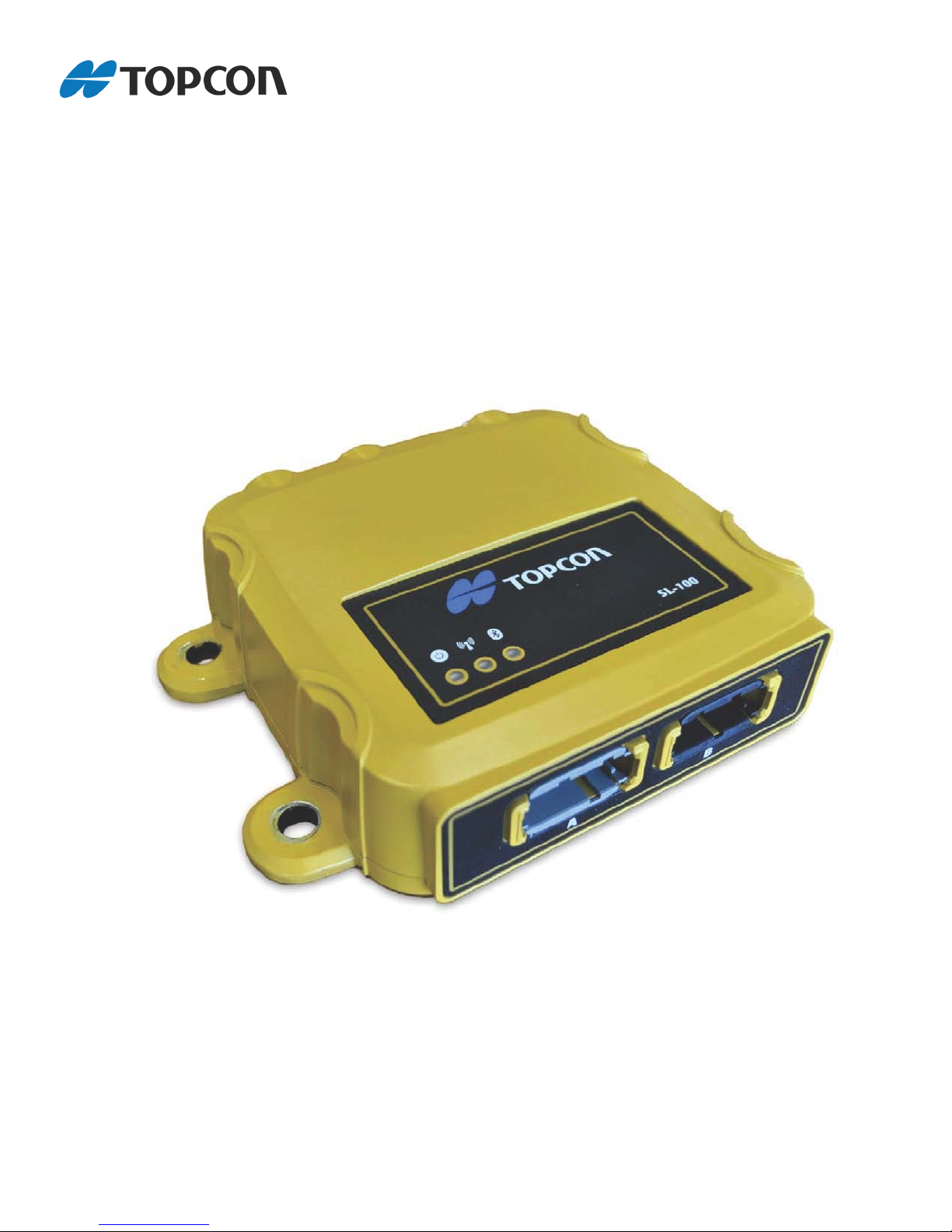
Developed as an add-on component to a standard Topcon 3D system, the SL-100 is a rugged
housing for the SL-R3 SiteLINK radio modem, providing a SiteLINK-ready solution on the job
site for a variety of construction machines.
This manual describes how to install the SL-100, radio antenna, and cables, and how to configure
your unit.
Figure 1. SL-100
1000221-01 KIT, SL-100 Upgrade
• 1 ea. ASSY, SL-100 W/ SL-R3
• 1 ea. Power Cable - SL-100 to MC-R3, 9 ft. 11 in. (3000mm)
• 1 ea. Ethernet Cable - SL-100 TO MC-R3, 9 ft. 11 in. (3000mm)
• 1 ea. Kit, Antenna Config SL-R3
• 1 ea. SL-100 Upgrade Kit Installation and Setup Guide
• 1 ea. #20 Deutsch Removal Tool
1000222-01 KIT, SL-100 - MC-R3 Breakout B Connector (Optional)
• 1 ea. SL-100 – MC-R3 Breakout B Connector
• 1 ea. DRC26-40 MC-R3 Breakout B Connector Dust Boot
1000220-01 SL-100 Mag Mount Kit (Optional)
P/N 1000226-01
1
Page 8
Installation
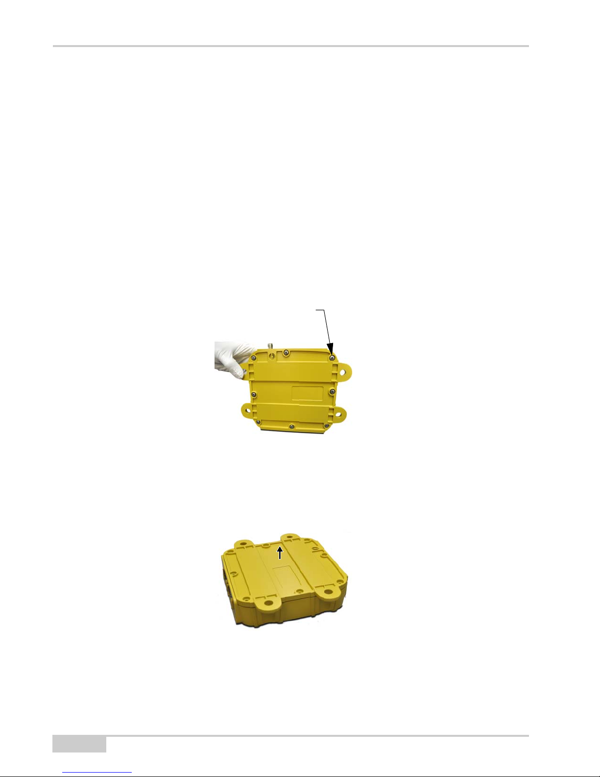
Remove Screw
8 Plcs.
Additional Parts Required
• 3DMC upgrade to:
– 7050-1106 Password, 3DMC Standard + SiteLINK
– 7050-1106 Password, 3DMC Standard + SiteLINK Advanced
• SIM Card (SIM APN, Username, Password)
Installation
SL-100 SIM Card
1. Remove the eight (8) retaining screws from the base of the SL-100.
2. Remove the base.
2
Figure 2. Remove Screws
Figure 3. Remove Base
SL-100 Upgrade Kit Installation and Setup Guide
Page 9
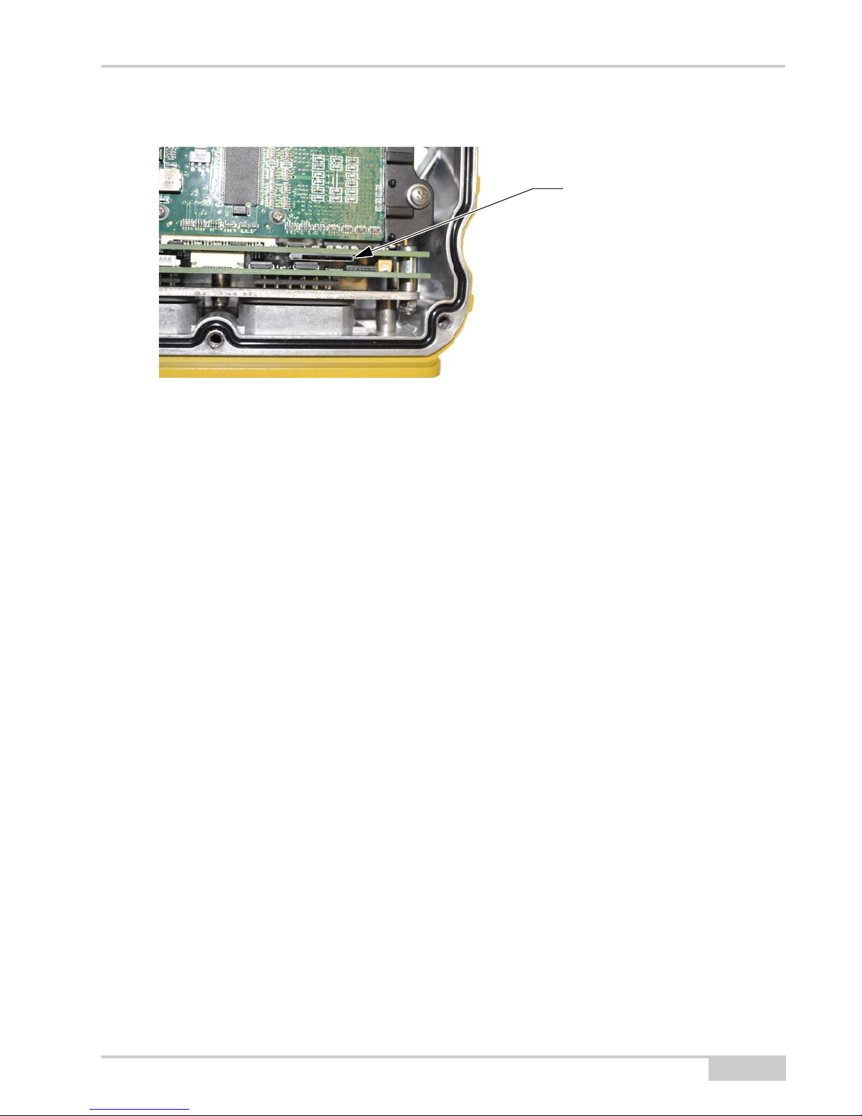
Mag Mount Kit (Optional)
SIM Card Slot
3. Insert the SIM card into the SIM card slot.
Figure 4. Insert SIM Card
4. Reinstall the eight (8) retaining screws onto the SL-100 base using Blue Loctite (not
included), and torque to 12 in-lbs
.
Mag Mount Kit (Optional)
If you are installing the optional Mag Mount Kit (P/N: 1000220-01), refer to the Mag Mount
Installation Instructions (P/N: 7010-1026).
P/N 1000226-01
3
Page 10
Installation
NOTICE
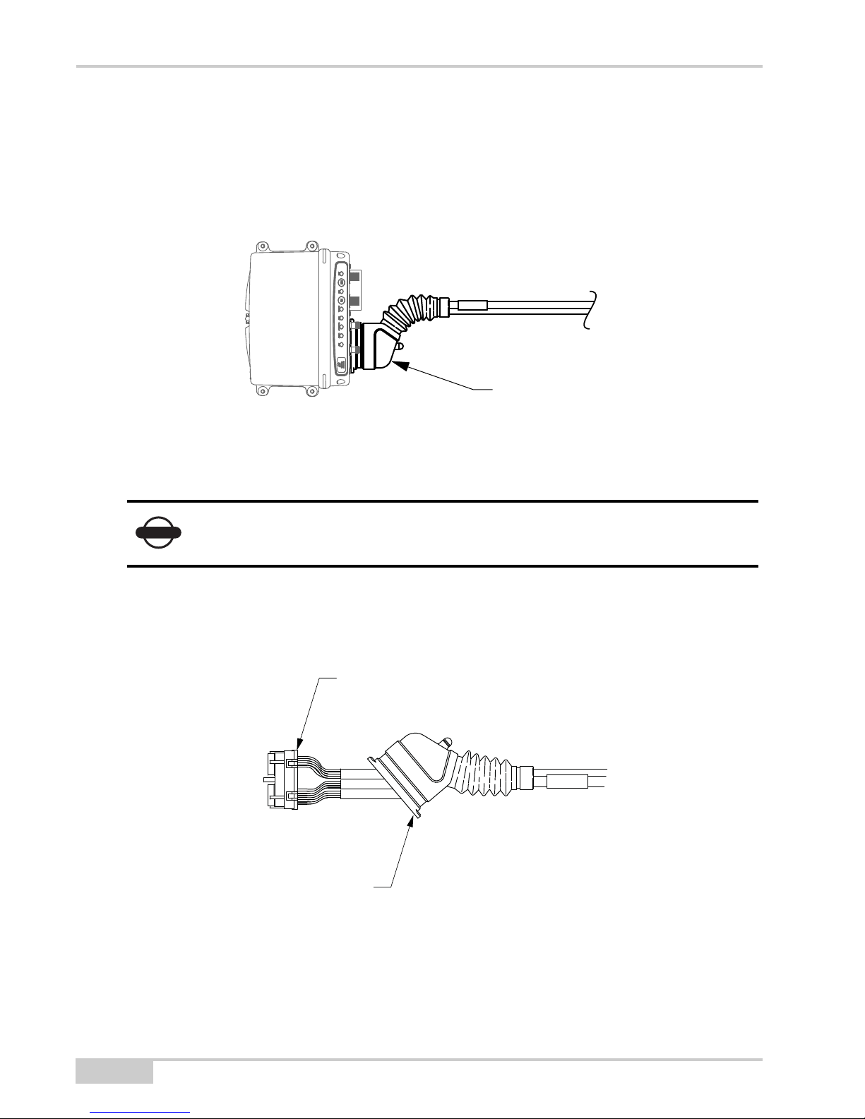
Breakout B Connector
Rubber Boot
Wire Comb
9911-1014 Ethernet Cable to
MC-R3 Breakout B Cable Connection
1. Locate the existing installed MC-R3 Breakout B cable attached to Conn B of the MC-R3.
Figure 5. Breakout B Cable
2. Disconnect the Breakout B cable from the MC-R3.
If the existing system does not have a Breakout B cable attached to Conn B, you
must have the SL-100 MC-R3 B Connector Kit (P/N: 1000222-01) to complete
the install.
3. Pull back the rubber boot on the Breakout B cable to expose the wire comb.
4
Figure 6. Expose Wire Comb
SL-100 Upgrade Kit Installation and Setup Guide
Page 11
9911-1014 Ethernet Cable to MC-R3 Breakout B Cable Connection
Wire Comb
Remove 4
Sealing Plugs
Ethernet Cable Routed through
Rubber Boot
Rubber Boot
Wire Comb
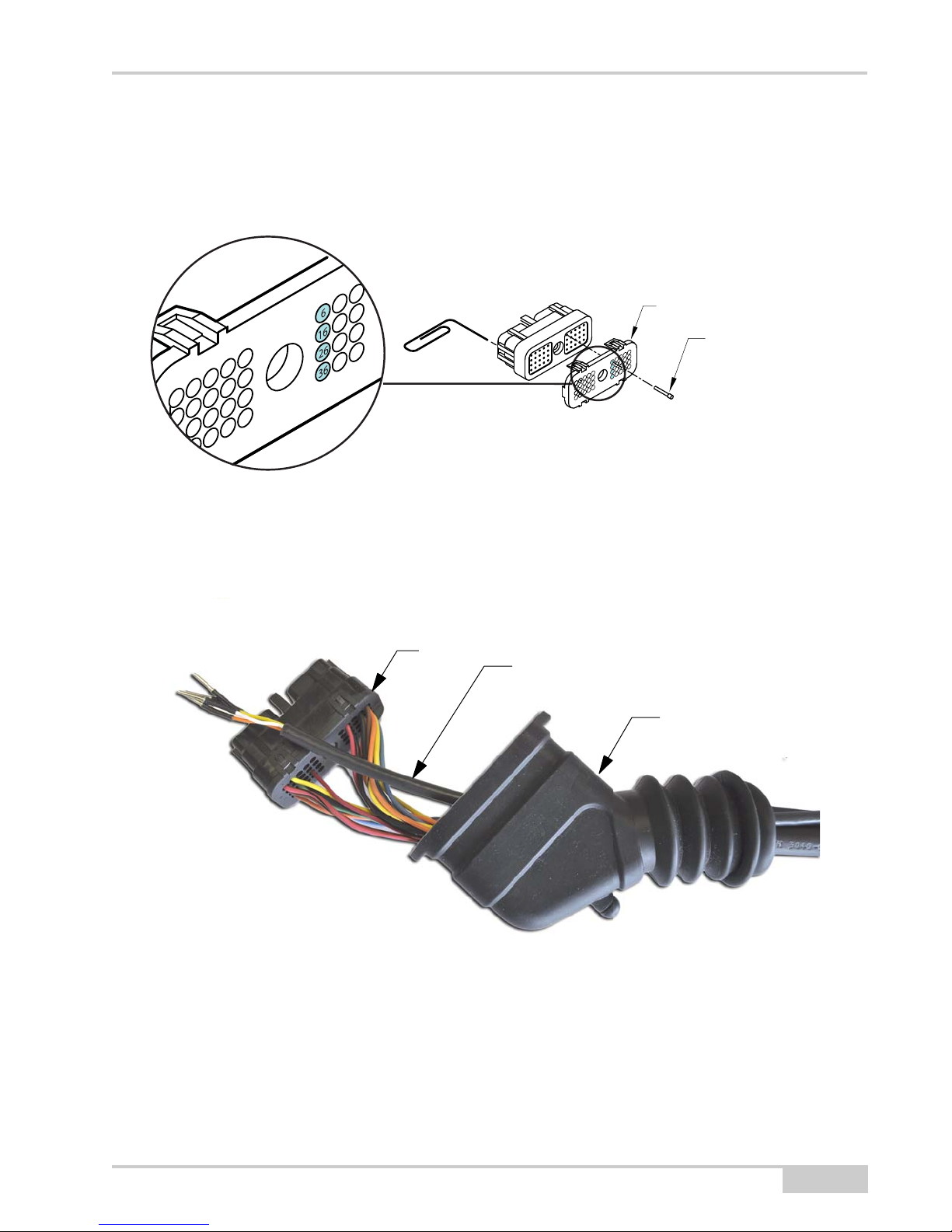
4. To remove the sealing plugs from pins 6, 16, 26, and 36 from the wire comb
(see Figure 7), insert a large paper clip, or something similar into the mating end of the
connector, and push out the sealing plug.
Figure 7. Remove 4 Sealing Plugs
5. Route the new Ethernet cable through the rubber boot.
Figure 8. Route Ethernet Cable through Boot
P/N 1000226-01
5
Page 12

Installation
BLUE
YELLOW
WHITE
Ethernet Cable
(9911-1014)
ORANGE
MC-R3
Breakout B
Eth RX+
Eth RX-
Eth TX+
Eth TX-
26
16
6
36
Breakout A Connector
6. Install the wires according to the colors noted in the wiring diagram (Figure 9). Slide the
7. Connect the MC-R3 Breakout B cable to the MC-R3 Controller, slide the rubber boot back
wires/contacts into the connector until they lock in place.
Figure 9. Ethernet to MC-R3 Breakout B Cable Wiring Diagram
into place, and tighten the Breakout B Connector screw.
9911-1015 Power and Serial Cable to
MC-R3 Breakout A Cable Connection
1. Locate the existing installed MC-R3 Breakout A cable attached to Conn A of the MC-R3.
Figure 10. Breakout A Cable
2. Disconnect the cable from the MC-R3.
6
SL-100 Upgrade Kit Installation and Setup Guide
Page 13

9911-1015 Power and Serial Cable to MC-R3 Breakout A Cable Connection
Rubber Boot
Wire Comb
Wire Comb
Remove 6
Sealing Plugs
3. Pull back the rubber boot on the Breakout A cable to expose the wire comb.
Figure 11. Expose Wire Comb
4. To remove the sealing plugs from pins 5, 17, 27, 34, 37 & 39 from the wire comb, insert a
large paper clip, or something similar, into the mating end of the connector, and push out
each sealing plug.
Figure 12. Remove 6 Sealing Plugs
P/N 1000226-01
7
Page 14

Installation
Power/Serial Cable Routed through
Rubber Boot
Rubber Boot
Wire Comb
ORANGE
BROWN
YELLOW
Power/Serial Cable
(9911-1015)
BLUE
MC-R3
Breakout A
MAIN A TX
MAIN A RX
AUX A TX
AUX A RX
RED
V SUPPLY
BLACK
GROUND
27
5
34
17
37*
39**
* If in use, use pin 38 as an alternative to pin 37
** If in use, use pin 19 or 29 as an alternative to pin 39
5. Route the new Power/Serial cable (9911-1015) through the rubber boot.
Figure 13. Route Power/Serial Cable through Boot
6. Install the wires according to the colors noted in the wiring diagram (Figure 14). Slide the
wires/contacts into the connector until they lock in place.
Figure 14. Power/Serial to MC-R3 Breakout A Cable Wiring Diagram
7. Connect the MC-R3 Breakout A cable to the MC-R3 Controller, slide the rubber boot
back into place, and tighten the Breakout B Connector screw.
8
SL-100 Upgrade Kit Installation and Setup Guide
Page 15

SL-100 and SL-R3 Antenna Installation
SL-100 and SL-R3 Antenna Installation
Install the SL-100 and the SL-R3 antenna on your machine where appropriate.
SL-100 Cable Connection
Connect the following cables to the SL-100
From the MC-R3 Controller Cable
• 9911-1014 - Ethernet Cable (Black Connector)
• 9911-1015 - Power Cable (Grey Connector)
From the SL-R3 Antenna
• 9050-18 - SL-R3 Antenna
P/N 1000226-01
9
Page 16

Installation
Notes:
10
SL-100 Upgrade Kit Installation and Setup Guide
Page 17
SL-100 Configuration
To use the GX-60 Display to configure the SL-100:
Enter SiteLINK Configuration Tool Web Interface
1. Power up your 3DMC SiteLINK system by turing on the GX-60 display. The SL-100 and
MC-R3 controller powers up with the GX-60.
2. Start Windows® Internet Explorer on the GX-60 Display.
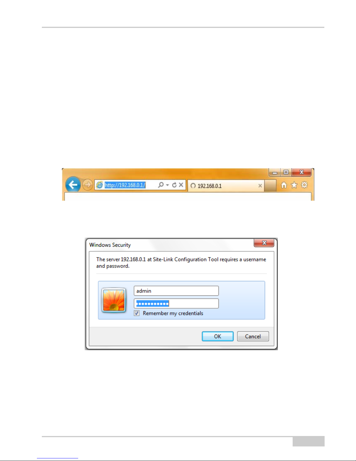
3. Using the on-screen keyboard, type 192.168.0.1 into Internet Explorer’s address bar to
connect to the SiteLINK Configuration Tool web interface.
Figure 1. Access SiteLINK Configuration Tool Web Interface
4. When prompted for the user name and password, enter ”admin” for both.
Figure 2. Enter SiteLINK Username and Password
P/N 1000226-01
11
Page 18
SL-100 Configuration
Check SL-R3 Firmware
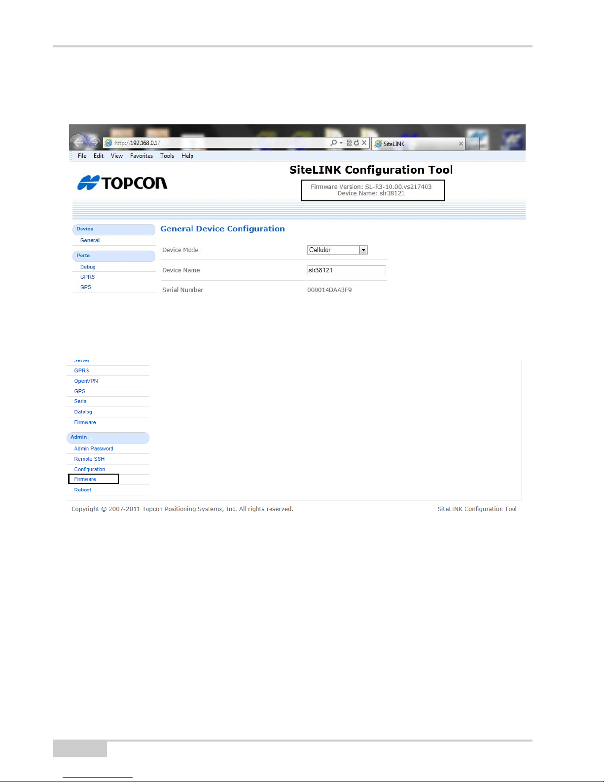
The firmware version is listed at the top of every page (Figure 3).
Figure 3. Firmware Version
If the firmware needs upgrading, click Admin --> Firmware on the left side of the page and load
the new firmware (Figure 4).
Figure 4. Load New Firmware
12
SL-100 Upgrade Kit Installation and Setup Guide
Page 19

Configure SL-100 for Cellular
NOTICE
1. Click Device --> General on the left side of the page to enter the General Device
Configuration page (Figure 5).
Figure 5. Configure Device Mode to Cellular
2. Check that the Device Mode is set to Cellular (factory default). See Figure 6.
• If the Device Mode is set to Cellular, skip step 3 and go to “Configure SIM Card
(GPRS)” on page 1-15.
• If the Device Mode is not set to Cellular, select Cellular from the Device Mode
drop-down menu, and press Save.
Do not choose any option other than cellular.
P/N 1000226-01
13
Page 20

SL-100 Configuration
Figure 6. Device Mode - Cellular
3. Click Admin --> Reboot on the left side of the page to enter the Reboot page, and press
Reboot.
Figure 7. Reboot
14
SL-100 Upgrade Kit Installation and Setup Guide
Page 21

Configure SIM Card (GPRS)
NOTICE
1. Click Ports --> GPRS to enter the GPRS Port Configuration page (Figure 8).
2. Set the Function to GPRS Dialup.
3. Set the APN, Username, and Password as required by the SL-100’s SIM card. Your
cellular carrier provides this information.
Figure 8. Configure SIM Card
4. To confirm the cellular connection, click Status --> GPRS to enter the GPRS Status page
(Figure 9).
5. Check that the SIM Status displays Ready, and monitor that, after a few minutes, the
Status displays Connected.
As the GPRS Status page does not automatically update, it is necessary to
press the refresh button on the browser from time to time while waiting for
the Status to display Connected.
P/N 1000226-01
15
Page 22

SL-100 Configuration
Figure 9. Confirm Cellular Connection
Configure VPN (If Running VPN on the SiteLINK
Server)
1. Click Network --> OpenVPN to enter the Open VPN Status Connection page
Figure 10).
(
2. Check the OpenVPN Enabled and Check box.
3. Press Browse to select the VPN Configuration file supplied by the SiteLINK Server
administrator.
16
SL-100 Upgrade Kit Installation and Setup Guide
Page 23

4. After selecting the VPN Configuration file, press Save.
NOTICE
x
If you are not running VPN, do not check the OPENVPN Enabled check box.
Figure 10. VPN Configuration
P/N 1000226-01
17
Page 24

SL-100 Configuration
NOTICE
x
Configure SiteLINK Server
1. Click Network --> Server to enter the SiteLINK Server Configuration page, and enter
the information as given by the SiteLINK Server Administrator.
Figure 11. SiteLINK Server Configuration
2. To check the SiteLINK server status, click Status --> Server to enter the Server Status
page, and confirm that the Connection Status displays Connected.
If you plan to use GPS corrections from the SiteLINK Server, your SiteLink
Administrator must configure the server to output GPS corrections.
The GPS Status on the Server Status page should be OK.
18
SL-100 Upgrade Kit Installation and Setup Guide
Page 25

x
Figure 12. SiteLINK Server Status
P/N 1000226-01
19
Page 26
SL-100 Configuration
x
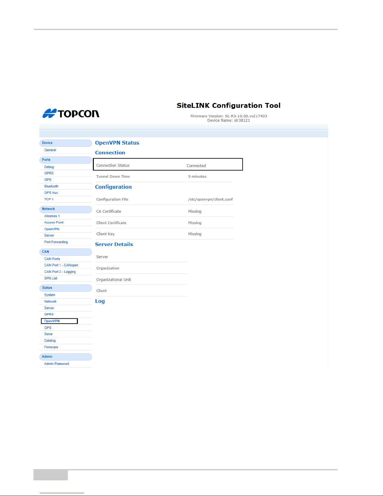
Check OpenVPN Status (If Running VPN)
Click Status --> OpenVPN to enter the OpenVPN Status page.
Check that the Connection Status displays Connected.
Figure 13. OpenVPN Status
20
SL-100 Upgrade Kit Installation and Setup Guide
Page 27
3DMC Configuration
x
Install 3DMC SiteLINK Authorization Codes
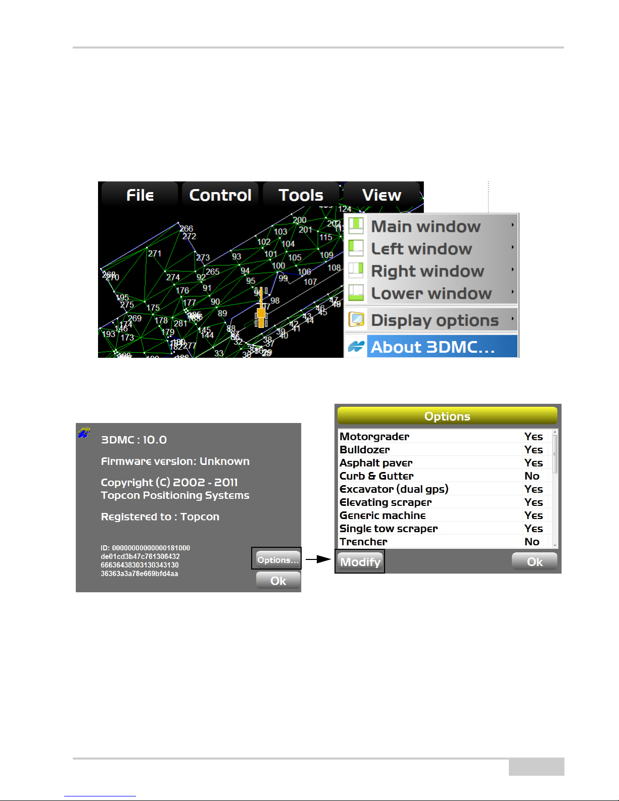
1. Tap Topcon Logo --> View --> About 3DMC.
Figure 14. About 3DMC Menu Selection
2. Tap Options --> Modify to display the Site-Link Connection screen
Figure 15. About 3DMC and Options Screens
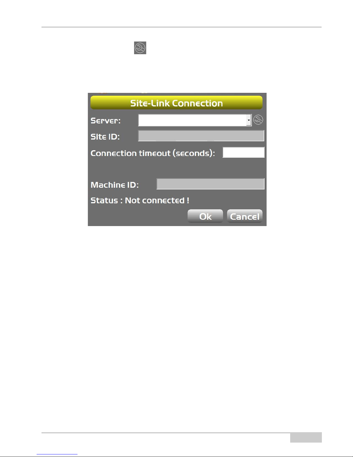
3. Enter the Authorization code provided by your dealer or SiteLINK administrator, and
press Ok (
Figure 16)
P/N 1000226-01
21
Page 28

3DMC Configuration
x
Figure 16. 3DMC SiteLINK Server Connection
Connecting to the SiteLINK Server
1. Tap Topcon Logo --> Tools --> Site-Link --> Network connection.
Figure 17. 3DMC SiteLINK Server Connection
22
SL-100 Upgrade Kit Installation and Setup Guide
Page 29
2. Tap the Wrench icon to the right of the Server field, and use the on-screen keyboard
x
to enter the SiteLINK Server IP address and Port in the format XXX.XXX.XXX.XXX/
PPPPP where X is the IP address and P is the Port Number as provided by the SiteLINK
server administrator (Figure 18). Press Ok.
Figure 18. 3DMC SiteLINK Server Connection
P/N 1000226-01
23
Page 30
3DMC Configuration
x
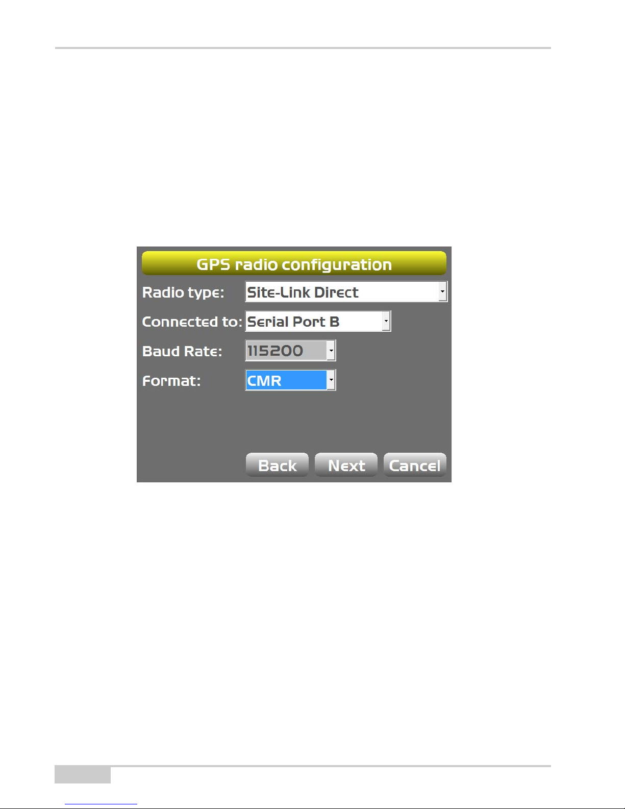
SiteLINK Direct
If the SiteLINK server is configured to output RTK corrections (by your SiteLINK administrator),
you can configure 3DMC to use RTK corrections from the SiteLINK Server.
1. In 3DMC, in the machine builder GPS radio configuration screen, select SiteLINK
Direct as the Radio type.
2. For Connected to, select Serial Port B.
3. Set the Format to match format that the SiteLINK server is configured to output
(CMR, CMR+, or RTCM 3.x).
24
Figure 19. 3DMC SiteLINK Server Connection
SL-100 Upgrade Kit Installation and Setup Guide
Page 31

Direct Network Connection
Direct network connection is another option to establish a network connection through the
SL-100.
1. In 3DMC in the machine builder GPS radio configuration screen, select Direct Network
Connection as the Radio type (
2. For Connected to, select Serial Port B.
3. The Format field automatically updates when the net mount point is selected in a later
step.
4. Press the Set and enter the Ntrip server IP address and port in the format xxx.xxx.xxx.xxx/
pppp (provided by your Topnet [NTRIP] Server administrator).
5. Press the Net and enter in the NTRIP User name and Password (provided by your Topnet
[NTRIP] Server administrator). The network type if you are running off Topnet is VRS.
6. Connect to the GPS.
7. Press Tools --> Configure radio --> Configure, and then press the Wrench icon to
download the mount points.
8. Select the required mount point, and 3DMC will connect to the NTRIP Server and begin
receiving GPS corrections.
Figure 19).
P/N 1000226-01
25
Page 32
SL-100 LED Status
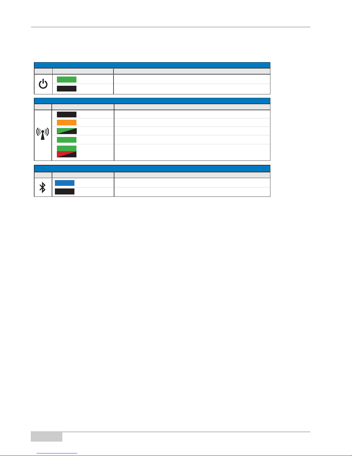
TRANSMITT LED (GREEN/RED/AMBER)
COLOR STATUS
No power
Booting
Not connected to SiteLINK Server (No GPRS connection information)
Connected to SiteLINK Server but not receiving RTK corrections
Connected to SiteLINK Server and receiving GPS corrections
BLUETOOTH® LED (BLUE)
COLOR STATUS
Bluetooth connection enabled and operational
Bluetooth connection unavailable
STATUS
On
No power
ICON
ICON
No Light
Amber
Green Flash
Solid Green
Solid Green
Solid Green
No Light
Solid Blue
No Light
w/Red Flash
SL-100 LED Status
POWER LED (GREEN)
COLORICON
26
SL-100 Upgrade Kit Installation and Setup Guide
Page 33

RF Radiation Hazard Warning
Safety Warnings
RF Radiation Hazard Warning
To ensure compliance with FCC and Industry Canada RF exposure requirements, this device must
be installed in a location where the antennas of the device will have a minimum distance of at
least 20 cm from all persons. Using higher gain antennas and types of antennas not certified for
use with this product is not allowed. The device shall not be co-located with another transmitter.
Installez l'appareil en veillant à conserver une distance d'au moins 20 cm entre les éléments
rayonnants et les personnes. Cet avertissement de sécurité est conforme aux limites d'exposition
définies par la norme CNR-102 at relative aux fréquences radio.
Regulatory Information
IC Statements
This Class (A or B) digital apparatus complies with Canadian ICES-003.
The term “IC:” before the radio certification number only signifies that Industry Canada technical
specifications were met.
Under Industry Canada regulations, this radio transmitter may only operate using an antenna of a
type and maximum (or lesser) gain approved for the transmitter by Industry Canada. To reduce
potential radio interference to other users, the antenna type and its gain should be so chosen that
the equivalent isotropically radiated power (e.i.r.p.) is not more than that necessary for successful
communication.
This device complies with Industry Canada licence-exempt RSS standard(s). Operation is subject
to thefollowing two conditions: (1) this device may not cause interference, and (2) this device
must accept anyinterference,including interference that may cause undesired operation of the
device.
Under Industry Canada regulations, this radio transmitter may only operate using an antenna of a
type and maximum (or lesser) gain approved for the transmitter by Industry Canada. To reduce
potential radio
interference to other users, the antenna type and its gain should be so chosen that the equivalent
isotropically radiated power (e.i.r.p.) is not more than that necessary for successful
communication.
P/N 1000226-01
27
Page 34

Regulatory Information
Déclaration de conformité IC:
Cet appareil numérique de la classe (A or B) est conforme à la norme NMB-003 du Canada.
Conformément à la réglementation d'Industrie Canada, le présent émetteur radio peut fonctionner
avec une antenne d'un type et d'un gain maximal (ou inférieur) approuvé pour l'émetteur par
Industrie Canada. Dans le but de réduire les risques de brouillage radioélectrique à l'intention des
autres utilisateurs, il faut choisir le type d'antenne et son gain de sorte que la puissance isotrope
rayonnée équivalente (p.i.r.e.) ne dépasse pas l'intensité nécessaire à l'établissement d'une
communication satisfaisante.
Ce matériel respecte les standards RSS exempt de licence d’Industrie Canada. Son utilisation est
soumise aux deux conditions suivantes:
(1) l’appareil ne doit causer aucune interférence, et
(2) l’appareil doit accepter toute interférence, quelle qu’elle soit, y compris les interférences
susceptibles d’entraîner un fonctionnement non requis de l’appareil.
Selon la réglementation d’Industrie Canada, ce radio-transmetteur ne peut utiliser qu’un seul type
d’antenne et ne doit pas dépasser la limite de gain autorisée par Industrie Canada pour les
transmetteurs. Afin de réduire les interférences potentielles avec d’autres utilisateurs, le type
d’antenne et son gain devront être définis de telle façon que la puissance isotrope rayonnante
équivalente (EIRP) soit juste suffisante pour permettre une bonne communication.
28
SL-100 Upgrade Kit Installation and Setup Guide
Page 35

Page 36

Topcon Positioning Systems, Inc.
7400 National Drive, Livermore, CA 94550
800∙443.4567 www.topconpositioning.com
SL-100 Installation and Setup Guide
P/N: 10000226-01 Rev A
©2012 Topcon Positioning Systems, Inc. All rights reserved. No unauthorized duplication.
REV Description ECO
ISO 9001:2000
FM 68448
 Loading...