

Page 1
i
Page 2

ii
Thank you for purchasing the Signature Series Model OC-2300 Ophthalmic Chair. Please read this
User's Manual carefully and place it in a convenient location for future reference.
WARNING: The installation of the chair shall be performed only by a qualified
technician.
!
WARNING: The chair is designed for use with TOPCON equipment. If any other
equipment is used, it shall meet the same certifications.
!
WARNING: Any service and/or repairs (other than replacement of the two exter-
nal fuses) shall be performed only by a qualified technician.
!
Precautions for Operation
• Installation: Never position the chair where it will be exposed to moisture, direct sunlight, dust, salty
air, chemical storage areas, excessive temperature or humidity. Install the chair in a stable place, free
of uneven floors, vibration and shock.
• Prior to Operation: Check all cords and/or cabling for proper connections.
• Operation: Take appropriate action to stop the chair from moving (leaving the patient in a safe
condition) if a malfunction occurs.
• After Operation: Never disconnect any plugs by pulling on the cable. Doing so may cause damage to
the internal connections. If the chair has been idle for a period of time, check all functions and safety
features for normal operation prior to reuse.
Safety Precautions
• The OC-2300 exam chair conforms to UL 2601-1 and CAN/CSA-C22.2 No. 601.1-M90. There is no
disposal of any waste products associated with the OC-2300 exam chair provided that all damaged
components are returned to Topcon.
WARNING: Do not load the chair with more than the maximum specified
capacity listed in the specifications section.
!
WARNING: Do not sit on the chair armrests. Doing so may cause damage to
internal chair components.
!
WARNING: If the chair makes a strange noise, discontinue use of the chair
!
Precautions for Repair
• When disassembling, repairing, and reassembling the OC-2300, be very careful not to scratch or
damage the various mechanical and electrical components of the chair.
• Always disconnect the power cord when trouble-shooting or repairing electrical system components,
unless power is absolutely required to perform the repair.
2001010038 Revision C, 9/04
Page 3

iii
CONTENTS
1.0 NOMENCLATURE 1
1.1 Model OC-2300 Main Components 1
2.0 PERFORMANCE AND SPECIFICATIONS 1
3.0 ASSEMBLY 3
3.1 Tools 3
3.2 Ophthalmic Chair / Stand Position 3
3.3 Electrical Connections 3
3.4 Alternate Connections 3
3.5 Power Up 4
4.0 OPERATION 4
4.1 Elevation Control 4
4.2 Motorized Recline Control 4
4.3 Auto-Return Control 4
4.4 Memory Controls 5
4.5 Cancel Button 5
4.6 Swivel Brake Operation 5
4.7 Armrest Retraction 5
4.8 Headrest Position 5
4.9 Footrest Retraction 5
5.0 ADJUSTMENTS 6
5.1 Headrest Locking Tension 6
5.2 Swivel Brake Adjustment 6
5.3 Armrest Adjustment 6
6.0 MAINTENANCE 7
6.1 Paint and Nonmetallic Parts 7
6.2 Upholstery 7
7.0 TROUBLE SHOOTING 7
Page 4
1
1.0 NOMENCLATURE
1.1 Signature Series Model OC-2300 Main Components
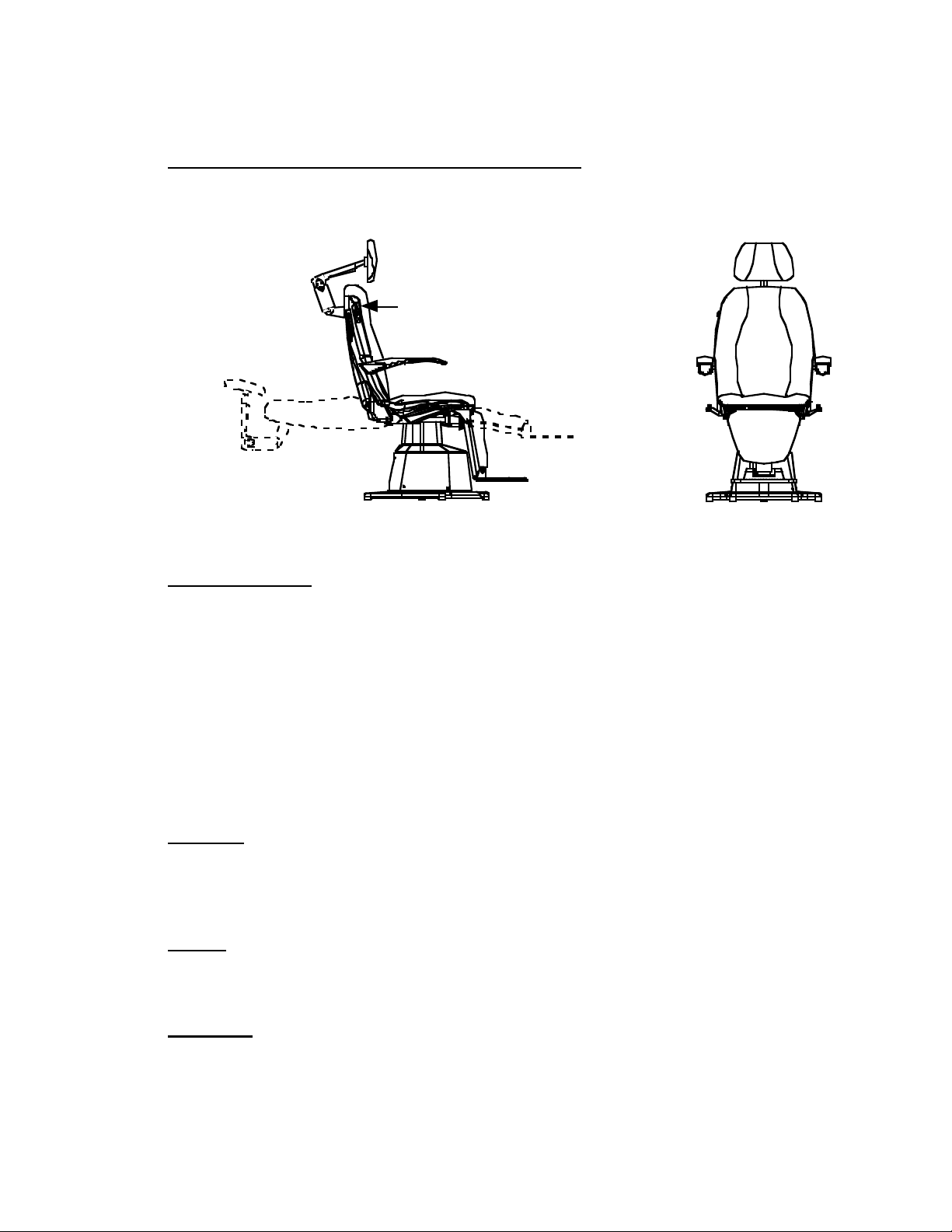
Figure 1 shows the primary features and key components of the OC-2300 Ophthalmic Chair.
Use the figure as a reference.
Recline
Position
Footrest
Headrest
Armrest
Brake
Handle
(both
sides)
Chair Controls
(both sides)
2.0 PERFORMANCE & SPECIFICATIONS
Chair Dimensions
• Overall: 55” (1397mm)/ 53” (1346mm)* (High) x 28 ” (711mm)
Wide x 40” (1016mm) Deep
• Seat Height (retracted): 22.5” (571mm)/ 20.0” (508mm)*
• Seat Height (full stroke): 35.0” (889mm)/ 29.0” (737mm)*
• Footrest Height: 3.5” (89mm)/ 1.5” (38mm)*
• Full Recline Length: 75” (1905mm)
• Mode of Operation: Continuous Use
• Type of Protection: Class 1 protection (Against Electrical Shock)
• Ingress of Water Protection: Ordinary Protection (IPX0)
• AP or APG: Not AP or APG equipment
Electrical
• Voltage, Current, Frequency:
US Versions: 120VAC (±10%), 7 A, 60 Hz
Non-US Versions: 240VAC (±10%), 3 A, 50Hz
Weight
• Chair Net Wt.: 286 lbs. (129 kg)
• Chair Capacity: 500 lbs. (227 kg)
Movement
• Elevation Stroke: 12.5” (318mm)/ 9” (229mm) *
• Range of Rotation: 355 degrees
• Recline Angle: 70 degrees
Page 5

2
Environmental Operating Conditions
• Ambient Temperature Range: 50 to 104 Degrees F (10 to 40 Degrees C)
• Relative Humidity Range: 30 to 75%
• Atmospheric Pressure Range: 10.1 to 15.4 psi (700 to 1060 hPa)
Environmental Storage/Transportation Conditions
• Ambient Temperature Range: -20 to 130 Degrees F (-23 to 54 Degrees C)
• Relative Humidity Range: 30 to 95%
• Atmospheric Pressure Range: 10.1 to 15.4 psi (700 to 1060 hPa)
• Acceptable Storage Time
(in operating environment): 5 years
(in extreme environment): 20 days
* Denotes dimensions for the High/Low lift configurations
SYMBOLS FOUND ON THE OC-2300 CHAIR
Protective Earth ground location
CAUTION: Electrical shock possibility
!
ATTENTION: Information provided in manual
Alternating Current (AC) Symbol
UP Symbol
DOWN Symbol
Forward Symbol
Backward Symbol
Direct Current (DC) Symbol
Page 6

3
3.0 ASSEMBLY
3.1 Tools
Phillips Screw Driver
5/32” and 3/16” Allen Wrench
3.2 Ophthalmic Chair / Stand Position
1) Place the chair next to the base of the ophthalmic stand or cabinet. Allow it to
come to room temperature.
2) Remove the red shipping bolt, which secures the chair seat to the base
assembly (Remove the seat upholstery if installed).
WARNING: Red shipping bolt must be removed before power up.
!
3) Install the upholstery set to the chair (if not already installed) with the
instructions included in the upholstery box.
3.3 Electrical Connections
1) Connect the chair power cable into the appropriate wall outlet or into the
ophthalmic stand.
2) Connect the chair control cable to the ophthalmic stand and check the vertical
movement of the ophthalmic chair.
3.4 Alternate Connections
When the Ophthalmic Chair model OC-2300 is not used in conjunction with a
Topcon ophthalmic stand, use the table below to configure the electrical inputs
correctly.
Stand Cable Wire Code
Pin
Number
Wire Function
Wire Color
1
Ground
Green
2
Neutral
White
3
Hot
Black
4
Up
Red
5
Down
Violet
6
Auto-Return
Orange
7
Relay Engage
Brown
8
Safety Switch
Yellow
9
Safety Switch
Blue
WARNING: If the chair is used with a Topcon IS-800 stand, the plastic base shroud (non-fuse
side) must be removed to make a configuration change on the circuit board. This
will make the IS-800 safety switch feature operable.
Page 7

4
1) If the chair has a 1st generation circuit board, remove the blue jumper pin
located between the transformer and the 9-pin connector. Re-install the base
shroud.
OR
2) If the chair has a 2nd generation circuit board, move the red jumper pin located
between the 9-pin connector and the 6-pin connector labeled ‘Stand Safety’
from the OFF position to the ON position. Re-install the base shroud.
3.5 Power Up
Plug the chair power cord into a wall receptacle or into the exam stand or cabinet
system. The chair control membrane switches should illuminate to indicate that the
chair is operational. Perform a test of all chair features to verify proper function.
Refer to the operation section of this document for details.
4.0 SYSTEM OPERATION
The OC-2300's sturdy design and motorized recline features make it an excellent choice for
Ophthalmic and Optometric exam rooms.
Each of the chair control membrane switch buttons performs a specific function. Refer to
Performance and Specifications for the button symbols and their corresponding functions.
4.1 Elevation Control
Height adjustment of the full power recline ophthalmic chair, model OC-2300, is
made by pressing the appropriate arrow button on either membrane switch located on
the sides of the back or with an optional footswitch. The chair may also be controlled
by the UP, DOWN and AUTORETURN buttons on the exam stand.
4.2 Motorized Recline Control
The motorized recline buttons, located on the sides of the backrest, recline and
upright the backrest. To recline the patient, press the back arrow button on one of the
membrane switches. Release the button once the desired position is achieved. You
may also preset one or both of the memory buttons to a predetermined condition. To
return the patient to the upright position press the forward arrow button on one of the
membrane switches. Release the button once the chair is upright. You may also press
the AUTORETURN button to bring the chair fully upright and fully down. An
optional dual function footswitch may also be used to recline the chair.
4.3 Auto-Return Control
An AUTORETURN button is located on each membrane switch and on most exam
stands. Pressing the AUTORETURN button will automatically return the chair to the
fully down and fully upright position.
WARNING: Check all power cords and electrical connections for damage prior to
powering up the system.
!
Page 8

5
4.4 Memory Controls
4.4.1 Programming
1) Press the AUTORETURN button to position the chair in the fully down and
fully upright position (home position).
2) Using one of the membrane switches located in the sides of the chair backrest,
move the chair to a desired position.
3) Press and hold one of the memory buttons for 3 seconds. An audible 2-beep
sequence indicates that the position has been recorded in memory. Once
memory programming is complete, the settings will be retained even if power
is cut to the chair. Repeat steps 1 through 3 to set a new memory position.
4) Press and release the appropriate memory button to move the chair to the
desired position.
NOTE: Moving the chair up and down from the footswitch or stand console may
cause the chair to exhibit some inaccuracy in locating the memory position
settings. To correct this, press the auto-return button to “re-home” the
chair then continue to use the controls as normal.
4.5 Cancel Button
A CANCEL button is located on each membrane switch. Pressing either CANCEL
button will terminate any automatic motion, such as auto-return and/or movement to
memory positions. As an additional safety feature, pressing any button on either chair
membrane switch will also terminate any automatic motion.
4.6 Swivel Brake Operation
To rotate the chair, move the swivel brake handle to the released position
(perpendicular to the floor), rotate the chair to the desired position, then move the
swivel brake handle to the activated position (parallel to the floor) to secure the chair
in position.
4.7 Armrest Retraction
One or both of the armrests may be pivoted up out of the way if desired. Press the
latch release button in the middle underside of the armrest then lift up on the
armrest. To return the armrest to the horizontal position, simply pivot the armrest
back down until it latches.
4.8 Headrest Position
The headrest assembly consists of a 2 pivot-articulating clamp as well as a pivoting
pillow mount. The headrest assembly has a very wide adjustment range and can
accommodate any examination situation. The articulating headrest position may be
adjusted as desired by releasing the clamp-locking handle, pivoting the headrest into
position, then re-activating the clamp-locking handle.
4.9 Footrest Retraction
The footrest may be stowed for easier access to the patient, or for closer
examination or surgical purpose. Simply pivot the footrest up by lifting on the
front edge until it clicks into its stowed position.
Page 9

6
5.0 ADJUSTMENTS
5.1 Headrest Locking Tension
If the position of the chair headrest has begun to move with the clamp-locking
handle in the locked position, the headrest clamp may require an adjustment.
Follow the instructions below to adjust the headrest assembly.
Headrest Clamp Adjustment
5.1.1 Release the clamp-locking handle. Loosen the Phillips screw in the side of
the clamp body, and then turn the slotted adjustment screw in the end of
the clamp assembly to adjust the clamping tension. (Clockwise for more
tension, counter-clockwise for less tension). Adjust the clamp tension so
that the clamp-locking handle closes easily and the pivots at each end of
the clamp are secure. Repeat the adjustments until the proper adjustment is
achieved. Re-tighten the Phillips screw in the side of the clamp body to
secure the adjustment.
Pillow Mount Pivot Adjustment
5.1.2 Turn the small adjustment screw in the pillow mount clamp to adjust the
pillow mount clamp tension (Clockwise for more tension, counterclockwise for less tension. The clamp is properly adjusted when the
headrest pillow position can be adjusted easily, but has enough bind to
remain in the position that it is set to after adjustment.
5.2 Swivel Brake Adjustment
If the chair can be rotated while the swivel brake handle is in the activated
position (parallel to the floor) an adjustment may be required. The swivel brake
adjustment screw is located behind the lift assembly on the underside of the metal
chair seat. If the swivel brake clamping tension is too loose, move the swivel
brake handle to the released position (perpendicular to the floor) and turn the
adjustment screw with an Allen wrench (Clockwise for more tension, counterclockwise for less tension) until the proper adjustment is achieved. The swivel
brake is properly adjusted when the chair rotates freely with the swivel brake
released but does not rotate when the brake is activated.
5.3 Armrest Adjustment
The armrests may require periodic adjustment to maintain proper function.
Remove the three arm upholstery mounting screws, and then remove the arm
upholstery to gain access to the arm adjustment screw. Turn the flat head
adjustment screw in the back side of the armrest casting with an Allen wrench to
adjust the amount of play in the armrest latching mechanism (clockwise for more
play, counter-clockwise for less play). The armrest latching mechanism is
adjusted properly when the mechanism engages properly when the armrest is
down, but has minimal vertical play once engaged. Reinstall the arm upholstery
after performing the adjustment.
The armrest height and relative position can be adjusted. Remove the backrest
upholstery to gain access to the adjustment screws. Tighten/loosen the opposing
Page 10

7
set screws in the appropriate armrest stop to align the armrests with one another.
Reinstall the backrest upholstery after performing the adjustment.
6.0 MAINTENANCE
It is recommended that the exterior surfaces of the OC-2300 chair be cleaned periodically
to preserve the chair's appearance. Cleaning should be performed at least every six
months.
6.1 Cleaning Painted and Nonmetallic Parts
Dirt and oils can be easily removed from painted or nonmetallic chair components
with a mild soap and water solution and a clean damp cloth. Use a soft, clean,
cloth to wipe the chair dry after cleaning.
6.2 Upholstery Cleaning
Use the same procedure as described above.
7.0 TROUBLE SHOOTING
If the chair malfunctions or is inoperative, perform the following checks prior to seeking
assistance.
1. Check to see that all connector cords and/or cables are securely connected.
2. Replace any blown fuses.
Fuse Replacement
WARNING: Do not attempt fuse replacement without first disconnecting the
chair from the power source.
!
WARNING: Any service and/or repairs (other than replacement of the two exter-
nal fuses) shall be performed only by a qualified technician.
!
The main power fuses are located in the rear of the base assembly in the LH side plastic shroud.
Unplug the chair from the AC power source. Twisting the fuse cap counter-clockwise and
simultaneously pressing down easily replace the fuses. Carefully remove the fuse and check for
breaks in the filament or for any corrosion at the ends. If in doubt, test the fuses with an
Ohmmeter. Obtain replacement fuses at a hardware/electronics store if it they are damaged or
blown. Once the fuse has been properly inspected or replaced, place it into the cap and re-install
it by turning the cap clockwise and pressing down simultaneously. Note: If the fuse cap is not
fully inserted the unit will not function.
Fuse Rating Table
Location
Fuse
100~120 Volt
220~240 Volt
Base Shroud
Primary
7A 250 v - SB
3A 250 v - SB
Base Shroud
Secondary
7A 250 v - SB
3A 250 v - SB
WARNING: Do not expose painted or nonmetallic parts or upholstery to any
volatile solvents such as benzene or paint thinner as these agents
may cause permanent damage.
!
Page 11

8
If problems persist, call your dealer or Topcon for assistance.
Topcon Medical Systems, Inc.
37 West Century Road
Paramus, NJ 07652
800-223-1130
www.topconmedical.com
 Loading...