

Topcon GPT-3002W Series, GPT-3000W Series, GPT-3003W, GPT-3007W Series, Series GPT-3005W Series Instruction Manual
Page 1
INSTRUCTION MANUAL
PULSE TOTAL STATION
GPT-3000W
GPT-3002W
GPT-3003W
GPT-3005W
GPT-3007W
SERIES
Page 2

Page 3

FOREWORD
Thank you for purchasing the TOPCON Pulse Total Station, GPT-3000W series.
For the best performance of the instruments, please carefully read these instructions and keep them in a convenient location for future reference.
1
Page 4
General Handling Precautions
Before starting work or operation, be sure to check that the instrument is
functioning correctly with normal performance.
Do not submerge the instrument into water.
The in st rument can no t be submerged underwater.
The instrument is designed based on the International Standard IP 66, therefore it is
protected from the normal rainfall.
Setting the instrument on a tripod
When mount ing the inst rument on a tr ipod, us e a wooden tripo d when possible. The
vibrations that may occur when using a metallic tripod can effect the measuring precision.
Installing the tribrach
If the tribrach is installed incorrectly, the measuring precision could be effected.
Occasional l y chec k the adjusting screws on the tribrach. Mak e sure the base fixing lever is
locked and the ba s e fi xi ng screws ar e tighten e d .
Guarding the instrument against shocks
When trans por t ing the i nstru ment, p rovide some prot ectio n to mini m i ze risk of shocks.
Heavy shocks may cause the measurement to be faulty.
Carrying the instrument
Alwa ys carry the instrument by its handgri p.
Exposing the instrument to extreme heat.
Do not leave the instrument in extreme heat for longer than necessary. It could adversely
affect its perform ance.
Sudden changes of temperature
Any sudden change of temperature to the instrument or prism may result in a reduction of
measuring distance range , i.e when taking the i nstrument out from a heat ed vehicle . Let
instrument accl im at e itself to ambient tem per at u re .
Battery level check
Confirm battery level remaining bef or e operating.
Taking the battery out
It is recommended not to take the battery out during the power is on. All the data stored is
poss ible gone at that time. So pl ease do your assembling or taking the b attery out after the
power is off.
Noise from the inside of instrument
When EDM turns on, the sound of motors from inside the instrument body may be
heard. This is normal and does not effect operation of the instrument.
2
Page 5
Display f or Safe Use
In order to encour age the safe use of p roducts and prevent any danger to the operator and
others or damage to properties, imp ortant warnings are put on the products and inserted in the
instruction manuals.
We suggest that everyone understand the meaning of the following displays and icons before
reading the “Safety Cautions” and text.
Display Meaning
WARNING
CAUTION
•Injury refers to hurt, burn, electric shock, etc.
•Physical damage refers to extensive damage to buildings or equipment and furniture.
Ignoring or disregard of this display may lead to the danger of death or
serious injury.
Ignoring or disregard of this display may lead to personal injury or physical damage.
Safety Cautions
WARNING
•There is a risk of fire, electric shock or physical harm if you attempt to disassemble or
repair the instrument yourself.
This is only to be carried out by TOPCON or an authorized dealer, only!
•Cause eye injury or blindness.
Do not look at the sun through a telescope.
•Laser beams can be dangerous, and can cause eye injury's if used incorrectly.
Never attempt to repair the instrument yourself.
•Cause eye injury or blindness.
Do not stare into beam.
•High temperature may cause fire.
Do not cover the charger while it is charging.
•Risk of fire or electric shock.
Do not use damaged power cable, plug and socket.
•Risk of fire or electric shock.
Do not use a wet battery or charger.
•May ignite explosively.
Never use an instrument near flammable gas, liquid matter, and do not use in a coal mine.
•Battery can cause explosion or injury.
Do not dispose in fire or heat.
•Risk of fire or electric shock.
Do not use any power voltage except the one given on manufacturers instructions.
•Battery can cause outbreak of fire.
Do not use any other type of charger other than the one specified.
•Risk of fire.
Do not use any other power cable other than the one specified.
•The short circuit of a battery can cause a fire.
Do not short circuit battery when storing it.
3
Page 6

CAUTION
•Use of controls or adjustment or performance of procedures other than those specified herein
may result in hazardous radiation exposure.
•Let the laser beam reach the aimed object or the target without anybody else in the laser beam
path. In case you operate laser beam open, avoid radiating laser beam to the height of man's
head. It is quite possible for the beam to enter into one's eyes, and it is possi ble to lose visual
sight temporarily , and lose one's caution and awareness of other dangers - avoid glaring beam.
•Do not connect or disconnect equipment with wet han ds, you ar e at risk of el ectric shocks if y ou
do!
•Risk of injury by overtur n the carrying case.
Do not stand or sit on the carrying cases.
•Please note that the tips of tripod can be hazardous, be aware of this when setting up or carrying the tripod.
•Risk of injury by falling down the instrument or case.
Do not use a carrying case with a damaged which belts, grips or latches.
•Do not allow skin or clothing to c ome i nto c ontact with acid from the batteries, if this does occur
then wash off with copious amounts of water and seek medical advice.
•A plumb bob can cause an injury to a person if used incorrectly.
•It could be dangerous if the instrument falls over, please ensure you attach a hand grip to the
instrument securely.
•Ensure that you mount the Tribrach correctly, failing to do so may result in injury if the tribrach
were to fall over.
•It could be dangerous if the instrument falls over, please check that you fix the instrument to
the tripod correctly.
•Risk of injury by falling down a tripod and an instrument.
Always check that the screws of tripod are tightened.
User
1)This product is for professional use only!
The user is required t o be a q ualified surveyor or have a good knowledge of surveying, in order to
understand the user and safety instructions, before operating, inspecting or adjusting.
2)Wear the required protectors (safety shoes, helmet, etc.) wh e n oper ating.
Exceptions from Responsibil ity
1)The user of this product i s expecte d to f ollo w all operat ing instruc tions and make periodi c chec ks of the
product’s performance.
2)The manufacturer, or its representatives, assumes no responsibility for results of a faulty or intentional
usage or misuse including any direct, indirect, consequential damage, and loss of profits.
3)The manufacturer, or its representatives, assumes no responsibility for consequential damage, and
loss of profits by any disaster, (an earthquake, storms, floods etc.).
A fire, accident, or an act of a third p arty and/or a usage any other usual conditions.
4)The manufac turer, or its representativ es , assum es no responsibil ity fo r any damage, and loss of profits
due to a change of data, loss of data, an interruption of business etc., caused by using the product or
an unusable product.
5)The manufac turer, or its representativ es , assum es no responsibil ity fo r any damage, and loss of profits
caused by usage except for explained in the user manual.
6)The manufacturer, or its representatives, assumes no responsibility for damage caused by wrong
movement, or action due to connecting with other products.
4
Page 7
Laser Saf ety
T
● Distance M e asurement
GPT-3000W series uses the invisible l ase r beam. The GPT-3000W series are manufactured and sold in
accordance with "Performance Standards for Light-Emitting Products" (FDA/BRH 21 CFR 1040) or
"Radiation Safety of Laser Products, Equipment Classification, Requirements and User`s Guide" (IEC
Publication 825) pr ovided on the safety standard fo r las er beam.
As per the said standard, the GPT -3000W series is classified as "Class 1 (l) Laser Products".
In case of any failure, do not disassemble the instrument. Contact TOPCON or your TOPCON dealer.
● Laser pointer and Plumb Laser (Plumb laser is s up p l i e d for certain markets)
GPT-3000W series plumb l aser and laser poi nt er use the visible laser beam. The GPT-3000W series
plumb laser and laser pointer are manufactured and sold in accordance with "Performance Standards
for Lig ht-Emitting Products" (FD A / BR H 21 CFR 1040) or "Ra di at i on Safety of Laser Products,
Equipment Classification, Requirements and User`s Guide" (IEC Publication 825) provided on the
safety standard f or laser beam.
As per the said standard, the GPT-3000W series plumb laser type is classified as "Class 2 (II) Lase r
Products".
In case of any failure, do not disassemble the instrument. Contact TOPCON or your TOPCON dealer.
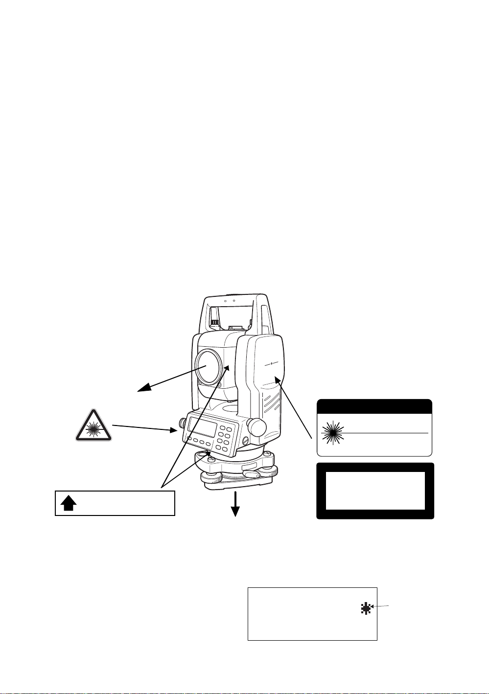
Labels
Find the labels which describes the caution and safety about the laser beam as follows in GPT-3000W
series.
We requ est you to replac e it one anyt i m e the cau tion labels are damaged or los t and paste a new one
at the same place. You can get the labels from Topcon or your dealer.
Laser aperture
Warning Lab el
Apertur e Label
AVOID EXPOSURE
LASER LIGHT IS EMITTED
FROM THIS APERTURE
Laser aperture
(Only for laser plummet type.)
Symbol mark while the laser is emitting.
The following symbol mark will appear at the
right side of the second line.
TILT SENSOR:[XY-ON]
X:-0°00'25"
Y: 0°00'20"
X-ON XY-ON OFF L.PL
Explanatory Label
CAUTION
LASER RADIATION
DO NOTSTARE INTO BEAM
WAVE LENGTH 620nm-690nm
1mW MAXIMUM OUTPUT
CLASS II LASER PRODUC
LASER RADIATION
DO NOT STARE INTO BEAM
Maximum output 1W@ Wave length 690nm CW
CLASS 2@LASER PRODUCT
Symbol mark
5
Page 8

Contents
FOREWORD . . . . . . . . . . . . . . . . . . . . . . . . . . . . . . . . . . . . . . . . . . . . . . . . . . 1
General Handling Precautions . . . . . . . . . . . . . . . . . . . . . . . . . . . . . . . . . . . . . . . . . . . . . . . 2
Display for Safe Use . . . . . . . . . . . . . . . . . . . . . . . . . . . . . . . . . . . . . . . . . . . . . . . . . . . . . . 3
Safety Cautions . . . . . . . . . . . . . . . . . . . . . . . . . . . . . . . . . . . . . . . . . . . . . . . . . . . . . . . . . . . . 3
User. . . . . . . . . . . . . . . . . . . . . . . . . . . . . . . . . . . . . . . . . . . . . . . . . . . . . . . . . . . . . . . . . . . . . 4
Exceptions from Responsibility . . . . . . . . . . . . . . . . . . . . . . . . . . . . . . . . . . . . . . . . . . . . . . . . 4
Laser Safety . . . . . . . . . . . . . . . . . . . . . . . . . . . . . . . . . . . . . . . . . . . . . . . . . . . . . . . . . . . . . . 5
Labels . . . . . . . . . . . . . . . . . . . . . . . . . . . . . . . . . . . . . . . . . . . . . . . . . . . . . . . . . . . . . . . . . . . 5
Symbol mark while the laser is emitting.. . . . . . . . . . . . . . . . . . . . . . . . . . . . . . . . . . . . . . . . . 5
Standard Set Composition . . . . . . . . . . . . . . . . . . . . . . . . . . . . . . . . . . . . . . . . . . . . . . . . . . . 9
1 NOMENCLATURE AND FUNCTIONS. . . . . . . . . . . . . . . . . . . . . . . . . . . 1-1
1.1 Nomenclature. . . . . . . . . . . . . . . . . . . . . . . . . . . . . . . . . . . . . . . . . . . . . . . . . . . . . . . . 1-1
1.2 Display . . . . . . . . . . . . . . . . . . . . . . . . . . . . . . . . . . . . . . . . . . . . . . . . . . . . . . . . . . . . . 1-3
1.3 Operating Key . . . . . . . . . . . . . . . . . . . . . . . . . . . . . . . . . . . . . . . . . . . . . . . . . . . . . . . 1-4
1.4 Function Key (Soft Key). . . . . . . . . . . . . . . . . . . . . . . . . . . . . . . . . . . . . . . . . . . . . . . . 1-5
1.5 Star key mode . . . . . . . . . . . . . . . . . . . . . . . . . . . . . . . . . . . . . . . . . . . . . . . . . . . . . . . 1-7
1.6 Serial signal RS-232C connector. . . . . . . . . . . . . . . . . . . . . . . . . . . . . . . . . . . . . . . . 1-10
1.7 Bluetooth™ communication . . . . . . . . . . . . . . . . . . . . . . . . . . . . . . . . . . . . . . . . . . . . 1-10
1.8 Laser Plummet ON/OFF (Only for Laser Plummet type). . . . . . . . . . . . . . . . . . . . . . 1-11
2 PREPARATION FOR MEASUREMENT . . . . . . . . . . . . . . . . . . . . . . . . . 2-1
2.1 Power Connection . . . . . . . . . . . . . . . . . . . . . . . . . . . . . . . . . . . . . . . . . . . . . . . . . . . . 2-1
2.2 Setting Instrument Up For Measurement. . . . . . . . . . . . . . . . . . . . . . . . . . . . . . . . . . . 2-2
2.3 Power Switch Key ON . . . . . . . . . . . . . . . . . . . . . . . . . . . . . . . . . . . . . . . . . . . . . . . . . 2-3
2.4 Battery Power Remaining Display . . . . . . . . . . . . . . . . . . . . . . . . . . . . . . . . . . . . . . . . 2-4
2.5 Vertical and Horizontal Angle Tilt Correction . . . . . . . . . . . . . . . . . . . . . . . . . . . . . . . . 2-5
2.6 How to Enter Alphanumeric characters . . . . . . . . . . . . . . . . . . . . . . . . . . . . . . . . . . . . 2-7
3 ANGLE MEASUREMENT . . . . . . . . . . . . . . . . . . . . . . . . . . . . . . . . . . . . 3-1
3.1 Measuring Horizontal Angle Right and Vertical Angle. . . . . . . . . . . . . . . . . . . . . . . . . 3-1
3.2 Switching Horizontal Angle Right/Left . . . . . . . . . . . . . . . . . . . . . . . . . . . . . . . . . . . . . 3-2
3.3 Measuring from the Required Horizontal Angle. . . . . . . . . . . . . . . . . . . . . . . . . . . . . . 3-2
3.3.1 Setting by Holding the Angle. . . . . . . . . . . . . . . . . . . . . . . . . . . . . . . . . . . . . . . . 3-2
3.3.2 Setting a Horizontal Angle from the Keys . . . . . . . . . . . . . . . . . . . . . . . . . . . . . . 3-3
3.4 Vertical Angle Percent Grade(%) Mode. . . . . . . . . . . . . . . . . . . . . . . . . . . . . . . . . . . . 3-3
3.5 Repetition Angle Measurement . . . . . . . . . . . . . . . . . . . . . . . . . . . . . . . . . . . . . . . . . . 3-4
3.6 Buzzer Sounding for Horizontal Angle 90° Increments. . . . . . . . . . . . . . . . . . . . . . . . 3-5
3.7 Compasses ( vertical angle). . . . . . . . . . . . . . . . . . . . . . . . . . . . . . . . . . . . . . . . . . . . . 3-6
4 DISTANCE MEASUREMENT . . . . . . . . . . . . . . . . . . . . . . . . . . . . . . . . . 4-1
4.1 Setting of the Atmospheric Correction . . . . . . . . . . . . . . . . . . . . . . . . . . . . . . . . . . . . . 4-1
4.2 Setting of the Correction for Prism Constant / Non-prism Constant. . . . . . . . . . . . . . . 4-1
4.3 Distance Measurement (Continuous Measurement) . . . . . . . . . . . . . . . . . . . . . . . . . . 4-2
4.4 Distance Measurement (N-time Measurement/Single Measurement). . . . . . . . . . . . . 4-3
4.5 Fine Mode/Tracking Mode/Coarse Mode. . . . . . . . . . . . . . . . . . . . . . . . . . . . . . . . . . . 4-4
4.6 Stake Out (S.O) . . . . . . . . . . . . . . . . . . . . . . . . . . . . . . . . . . . . . . . . . . . . . . . . . . . . . . 4-5
4.7 Offset Measurement. . . . . . . . . . . . . . . . . . . . . . . . . . . . . . . . . . . . . . . . . . . . . . . . . . . 4-6
4.7.1 Angle Offset. . . . . . . . . . . . . . . . . . . . . . . . . . . . . . . . . . . . . . . . . . . . . . . . . . . . . 4-7
4.7.2 Distance Offset Measurement. . . . . . . . . . . . . . . . . . . . . . . . . . . . . . . . . . . . . . . 4-9
4.7.3 Plane Offset Measurement . . . . . . . . . . . . . . . . . . . . . . . . . . . . . . . . . . . . . . . . 4-11
4.7.4 Column Offset Measurement . . . . . . . . . . . . . . . . . . . . . . . . . . . . . . . . . . . . . . 4-13
5 COORDINATE MEASUREMENT. . . . . . . . . . . . . . . . . . . . . . . . . . . . . . . 5-1
5.1 Setting Coordinate Values of Occupied Point . . . . . . . . . . . . . . . . . . . . . . . . . . . . . . . 5-1
5.2 Setting Height of the Instrument. . . . . . . . . . . . . . . . . . . . . . . . . . . . . . . . . . . . . . . . . . 5-2
5.3 Setting Height of Target (Prism Height) . . . . . . . . . . . . . . . . . . . . . . . . . . . . . . . . . . . . 5-2
5.4 Execution of Coordinate Measuring. . . . . . . . . . . . . . . . . . . . . . . . . . . . . . . . . . . . . . . 5-3
6 SPECIAL MODE (Menu Mode) . . . . . . . . . . . . . . . . . . . . . . . . . . . . . . . . 6-1
6.1 Application Measurement (PROGRAMS) . . . . . . . . . . . . . . . . . . . . . . . . . . . . . . . . . . 6-2
6
Page 9

6.1.1 Remote Elevation measurement (REM) . . . . . . . . . . . . . . . . . . . . . . . . . . . . . . . 6-2
6.1.2 Missing Line Measurement (MLM) . . . . . . . . . . . . . . . . . . . . . . . . . . . . . . . . . . . 6-5
6.1.3 Setting Z Coordinate of Occupied Point . . . . . . . . . . . . . . . . . . . . . . . . . . . . . . . 6-8
6.1.4 Area Calculation . . . . . . . . . . . . . . . . . . . . . . . . . . . . . . . . . . . . . . . . . . . . . . . . 6-11
6.1.5 Point to Line Measurement . . . . . . . . . . . . . . . . . . . . . . . . . . . . . . . . . . . . . . . . 6-14
6.2 Setting the GRID FACTOR . . . . . . . . . . . . . . . . . . . . . . . . . . . . . . . . . . . . . . . . . . . . 6-16
6.3 Setting Illumination of Display and Cross Hairs . . . . . . . . . . . . . . . . . . . . . . . . . . . . 6-17
6.4 Setting Mode 1. . . . . . . . . . . . . . . . . . . . . . . . . . . . . . . . . . . . . . . . . . . . . . . . . . . . . . 6-18
6.4.1 Setting Minimum Reading. . . . . . . . . . . . . . . . . . . . . . . . . . . . . . . . . . . . . . . . . 6-18
6.4.2 Auto Power Off . . . . . . . . . . . . . . . . . . . . . . . . . . . . . . . . . . . . . . . . . . . . . . . . . 6-19
6.4.3 Vertical and Horizon tal Angle Tilt correction ( Til t ON/OFF) . . . . . . . . . . . . . . . 6-20
6.4.4 Systematic Error of Instrument Correction . . . . . . . . . . . . . . . . . . . . . . . . . . . . 6-20
6.4.5 Selecting Battery Type . . . . . . . . . . . . . . . . . . . . . . . . . . . . . . . . . . . . . . . . . . . 6-21
6.4.6 Heater ON/OFF. . . . . . . . . . . . . . . . . . . . . . . . . . . . . . . . . . . . . . . . . . . . . . . . . 6-21
6.4.7 Setting RS-232C communication with external device . . . . . . . . . . . . . . . . . . . 6-22
6.4.8 Selecting Communication Port . . . . . . . . . . . . . . . . . . . . . . . . . . . . . . . . . . . . . 6-23
6.4.9 Confirming the Bluetooth™ Device Address and Setting the PIN code . . . . . . 6-24
6.5 Setting Contrast of Display . . . . . . . . . . . . . . . . . . . . . . . . . . . . . . . . . . . . . . . . . . . . 6-24
7 DATA COLLECTION . . . . . . . . . . . . . . . . . . . . . . . . . . . . . . . . . . . . . . . . 7-1
7.1 Preparation. . . . . . . . . . . . . . . . . . . . . . . . . . . . . . . . . . . . . . . . . . . . . . . . . . . . . . . . . . 7-3
7.1.1 Selecting a File for Data Collection . . . . . . . . . . . . . . . . . . . . . . . . . . . . . . . . . . . 7-3
7.1.2 Selecting a Coordinate File for Data Collection. . . . . . . . . . . . . . . . . . . . . . . . . . 7-4
7.1.3 Occupied Point and Backsight Point . . . . . . . . . . . . . . . . . . . . . . . . . . . . . . . . . . 7-4
7.2 Operational Procedure of DATA COLLECT. . . . . . . . . . . . . . . . . . . . . . . . . . . . . . . . . 7-7
7.2.1 Searching the recorded data. . . . . . . . . . . . . . . . . . . . . . . . . . . . . . . . . . . . . . . . 7-8
7.2.2 Entering PCODE / ID using PCODE Library . . . . . . . . . . . . . . . . . . . . . . . . . . . . 7-8
7.2.3 Entering PCODE / ID from the list of PCODE. . . . . . . . . . . . . . . . . . . . . . . . . . . 7-9
7.3 Data Collect Offset Measurement mode . . . . . . . . . . . . . . . . . . . . . . . . . . . . . . . . . . 7-10
7.3.1 Angle Offset Measurement . . . . . . . . . . . . . . . . . . . . . . . . . . . . . . . . . . . . . . . . 7-10
7.3.2 Distance Offset Measurement. . . . . . . . . . . . . . . . . . . . . . . . . . . . . . . . . . . . . . 7-12
7.3.3 Plane Offset Measurement . . . . . . . . . . . . . . . . . . . . . . . . . . . . . . . . . . . . . . . . 7-14
7.3.4 Column Offset Measurement . . . . . . . . . . . . . . . . . . . . . . . . . . . . . . . . . . . . . . 7-16
7.4 NEZ Auto Calculation. . . . . . . . . . . . . . . . . . . . . . . . . . . . . . . . . . . . . . . . . . . . . . . . . 7-17
7.5 Point to Line Measurement . . . . . . . . . . . . . . . . . . . . . . . . . . . . . . . . . . . . . . . . . . . . 7-18
7.5.1 To change to the point to line measurement. . . . . . . . . . . . . . . . . . . . . . . . . . . 7-18
7.5.2 Executing a point to line measurement. . . . . . . . . . . . . . . . . . . . . . . . . . . . . . . 7-19
7.6 Editing PCODE Library [PCODE INPUT]. . . . . . . . . . . . . . . . . . . . . . . . . . . . . . . . . . 7-20
7.7 Setting Parameter of Data Collect [CONFIG.]. . . . . . . . . . . . . . . . . . . . . . . . . . . . . . 7-21
8 LAYOUT. . . . . . . . . . . . . . . . . . . . . . . . . . . . . . . . . . . . . . . . . . . . . . . . . . 8-1
8.1 Preparation. . . . . . . . . . . . . . . . . . . . . . . . . . . . . . . . . . . . . . . . . . . . . . . . . . . . . . . . . . 8-3
8.1.1 Setting the GRID FACTOR . . . . . . . . . . . . . . . . . . . . . . . . . . . . . . . . . . . . . . . . . 8-3
8.1.2 Selecting Coordinate Data File . . . . . . . . . . . . . . . . . . . . . . . . . . . . . . . . . . . . . . 8-4
8.1.3 Setting Occupied Point . . . . . . . . . . . . . . . . . . . . . . . . . . . . . . . . . . . . . . . . . . . . 8-5
8.1.4 Setting Backsight Point . . . . . . . . . . . . . . . . . . . . . . . . . . . . . . . . . . . . . . . . . . . . 8-7
8.2 Executing a Layout. . . . . . . . . . . . . . . . . . . . . . . . . . . . . . . . . . . . . . . . . . . . . . . . . . . . 8- 9
8.2.1 Layout of Coordinates of Point to Line . . . . . . . . . . . . . . . . . . . . . . . . . . . . . . . 8-11
8.3 Setting a New Point . . . . . . . . . . . . . . . . . . . . . . . . . . . . . . . . . . . . . . . . . . . . . . . . . . 8-12
8.3.1 Side Shot Method . . . . . . . . . . . . . . . . . . . . . . . . . . . . . . . . . . . . . . . . . . . . . . . 8-12
8.3.2 Resection Method . . . . . . . . . . . . . . . . . . . . . . . . . . . . . . . . . . . . . . . . . . . . . . . 8-14
9 MEMORY MANAGER MODE . . . . . . . . . . . . . . . . . . . . . . . . . . . . . . . . . 9-1
9.1 Display Internal Memory Status. . . . . . . . . . . . . . . . . . . . . . . . . . . . . . . . . . . . . . . . . . 9-2
9.2 Searching Data . . . . . . . . . . . . . . . . . . . . . . . . . . . . . . . . . . . . . . . . . . . . . . . . . . . . . . 9-3
9.2.1 Measured Data Searching. . . . . . . . . . . . . . . . . . . . . . . . . . . . . . . . . . . . . . . . . . 9-3
9.2.2 Coordinate Data Searching. . . . . . . . . . . . . . . . . . . . . . . . . . . . . . . . . . . . . . . . . 9-5
9.2.3 PCODE LIBRARY Searching . . . . . . . . . . . . . . . . . . . . . . . . . . . . . . . . . . . . . . . 9-6
9.3 FILE MAINTENANCE . . . . . . . . . . . . . . . . . . . . . . . . . . . . . . . . . . . . . . . . . . . . . . . . . 9-7
9.3.1 Rename a File. . . . . . . . . . . . . . . . . . . . . . . . . . . . . . . . . . . . . . . . . . . . . . . . . . . 9-8
9.3.2 Searching Data in a File . . . . . . . . . . . . . . . . . . . . . . . . . . . . . . . . . . . . . . . . . . . 9-8
9.3.3 Deleting a File . . . . . . . . . . . . . . . . . . . . . . . . . . . . . . . . . . . . . . . . . . . . . . . . . . . 9-9
7
Page 10

9.4 Coordinate Data Direct Key Input . . . . . . . . . . . . . . . . . . . . . . . . . . . . . . . . . . . . . . . 9-10
9.4.1 Coordinate data input. . . . . . . . . . . . . . . . . . . . . . . . . . . . . . . . . . . . . . . . . . . . 9-10
9.4.2 PTL (Point to Line) data input . . . . . . . . . . . . . . . . . . . . . . . . . . . . . . . . . . . . . . 9-11
9.5 Delete a Coordinate Data from a File. . . . . . . . . . . . . . . . . . . . . . . . . . . . . . . . . . . . . 9-12
9.6 Editing PCODE Library . . . . . . . . . . . . . . . . . . . . . . . . . . . . . . . . . . . . . . . . . . . . . . . 9-13
9.7 Data Communications . . . . . . . . . . . . . . . . . . . . . . . . . . . . . . . . . . . . . . . . . . . . . . . . 9-14
9.7.1 Sending Data. . . . . . . . . . . . . . . . . . . . . . . . . . . . . . . . . . . . . . . . . . . . . . . . . . . 9-14
9.7.2 Loading Data. . . . . . . . . . . . . . . . . . . . . . . . . . . . . . . . . . . . . . . . . . . . . . . . . . . 9-16
9.7.3 Setting Parameter of Data Communications. . . . . . . . . . . . . . . . . . . . . . . . . . . 9-17
9.7.4 Confirming the parameters for Bluetooth™ communication . . . . . . . . . . . . . . . 9-19
9.8 Initialization . . . . . . . . . . . . . . . . . . . . . . . . . . . . . . . . . . . . . . . . . . . . . . . . . . . . . . . . 9-19
10 SET AUDIO MODE. . . . . . . . . . . . . . . . . . . . . . . . . . . . . . . . . . . . . . . . 10-1
11 SETTING THE PRISM / NON-PRISM CONSTANT VALUE . . . . . . . . 11-1
12 SETTING ATMOSPHERIC CORRECTION . . . . . . . . . . . . . . . . . . . . . 12-1
12.1 Calculation of Atmospheric Correction. . . . . . . . . . . . . . . . . . . . . . . . . . . . . . . . . . . 12-1
12.2 Setting of Atmospheric Correc tion Value. . . . . . . . . . . . . . . . . . . . . . . . . . . . . . . . . 12-1
13 CORRECTION FOR REFRACTION AND EARTH CURVATURE. . . . 13-1
13.1 Distance Calculation Formula . . . . . . . . . . . . . . . . . . . . . . . . . . . . . . . . . . . . . . . . . 13-1
14 POWER SOURCE AND CHARGING. . . . . . . . . . . . . . . . . . . . . . . . . . 14-1
14.1 On-board Battery BT-52QA . . . . . . . . . . . . . . . . . . . . . . . . . . . . . . . . . . . . . . . . . . . 14-1
15 DETACH/ATTACH OF TRIBRACH . . . . . . . . . . . . . . . . . . . . . . . . . . . 15-1
16 SELECTING MODE . . . . . . . . . . . . . . . . . . . . . . . . . . . . . . . . . . . . . . . 16-1
16.1 Items of the Selecting Mode. . . . . . . . . . . . . . . . . . . . . . . . . . . . . . . . . . . . . . . . . . . 16-1
16.2 How to Set Selecting Mode . . . . . . . . . . . . . . . . . . . . . . . . . . . . . . . . . . . . . . . . . . . 16-3
17 CHECK AND ADJUSTMENT. . . . . . . . . . . . . . . . . . . . . . . . . . . . . . . . 17-1
17.1 Checking and adjusting of instrument constant . . . . . . . . . . . . . . . . . . . . . . . . . . . 17-1
17.2 Checking the Optical Axis . . . . . . . . . . . . . . . . . . . . . . . . . . . . . . . . . . . . . . . . . . . . 17-2
17.2.1 Checking the optical axis of EDM and theodolite . . . . . . . . . . . . . . . . . . . . . . 17-2
17.2.2 Checking the optical axis of Laser pointer . . . . . . . . . . . . . . . . . . . . . . . . . . . 17-5
17.3 Checking/Adjusting the Theodolite Functions . . . . . . . . . . . . . . . . . . . . . . . . . . . . . 17-7
17.3.1 Checking /Adjusting the Plate Level . . . . . . . . . . . . . . . . . . . . . . . . . . . . . . . . 17-8
17.3.2 Checking /Adjusting the Circular Level . . . . . . . . . . . . . . . . . . . . . . . . . . . . . . 17-8
17.3.3 Adjustment of the Vertical Cross-hair . . . . . . . . . . . . . . . . . . . . . . . . . . . . . . . 17-9
17.3.4 Collimation of the Instrument. . . . . . . . . . . . . . . . . . . . . . . . . . . . . . . . . . . . . 17-10
17.3.5 Checking / Adjusting the Optical Plummet Telescope. . . . . . . . . . . . . . . . . . 17-11
17.3.6 Checking / Adjusting the Laser Plummet (For Laser Plummet type). . . . . . . 17-12
17.3.7 Adjustment of Vertical Angle 0 Datum. . . . . . . . . . . . . . . . . . . . . . . . . . . . . . 17-13
17.4 Ho w to Set t he I n st rume n t Constant Value . . . . . . . . . . . . . . . . . . . . . . . . . . . . . . 17-14
17.5 Adjustment of Compensation Systematic Error of Instrument . . . . . . . . . . . . . . . . 17-15
17.6 EDM Alignment Checking mode . . . . . . . . . . . . . . . . . . . . . . . . . . . . . . . . . . . . . . 17-16
18 PRECAUTIONS . . . . . . . . . . . . . . . . . . . . . . . . . . . . . . . . . . . . . . . . . . 18-1
19 SPECIAL ACCESSORIES . . . . . . . . . . . . . . . . . . . . . . . . . . . . . . . . . . 19-1
20 BATTERY SYSTEM . . . . . . . . . . . . . . . . . . . . . . . . . . . . . . . . . . . . . . . 20-1
21 PRISM SYSTEM. . . . . . . . . . . . . . . . . . . . . . . . . . . . . . . . . . . . . . . . . . 21-1
22 ERROR DISPLAYS . . . . . . . . . . . . . . . . . . . . . . . . . . . . . . . . . . . . . . . 22-1
23 SPECIFICATIONS . . . . . . . . . . . . . . . . . . . . . . . . . . . . . . . . . . . . . . . . 23-1
APPENDIX ...................................................................................... Appe ndix-1
Dual Axis Compensation ........ .............. ......................... .............. .............. .............Appendix-1
Precaution when Charging or Storing Batteries..................................................... Appendix-3
8
Page 11

Standard Set Composition
The numerical value in parentheses shows the quantity.
GPT-3000W series (with lens cap) (1) Plastic carrying case(1)
The form of a case will differ depending on a market.
On-board Battery BT-52QA (2) Battery charger BC-27BR or BC-27CR (1)
Sun shade(1) Plastic rain cover(1)
Plumb bob set(1) Tool kit with case (1)
[ rod pin(2), screwdriver, hexagonal wrench(2),
cleaning brush ]
Plumb bob hook is including in the tool kit case.
Instruction manual (1) Silicon cloth (1)
(Make sure that all of the above items are with the instrument when purchased.)
Remarks:
Battery charger B C-27CR is for AC 230V use and BC-27BR is for AC 12 0V us e.
9
Page 12
1 NOMENCLATURE AND FUNCTIONS
1 NOMENCLATURE AN D FUN CTION S
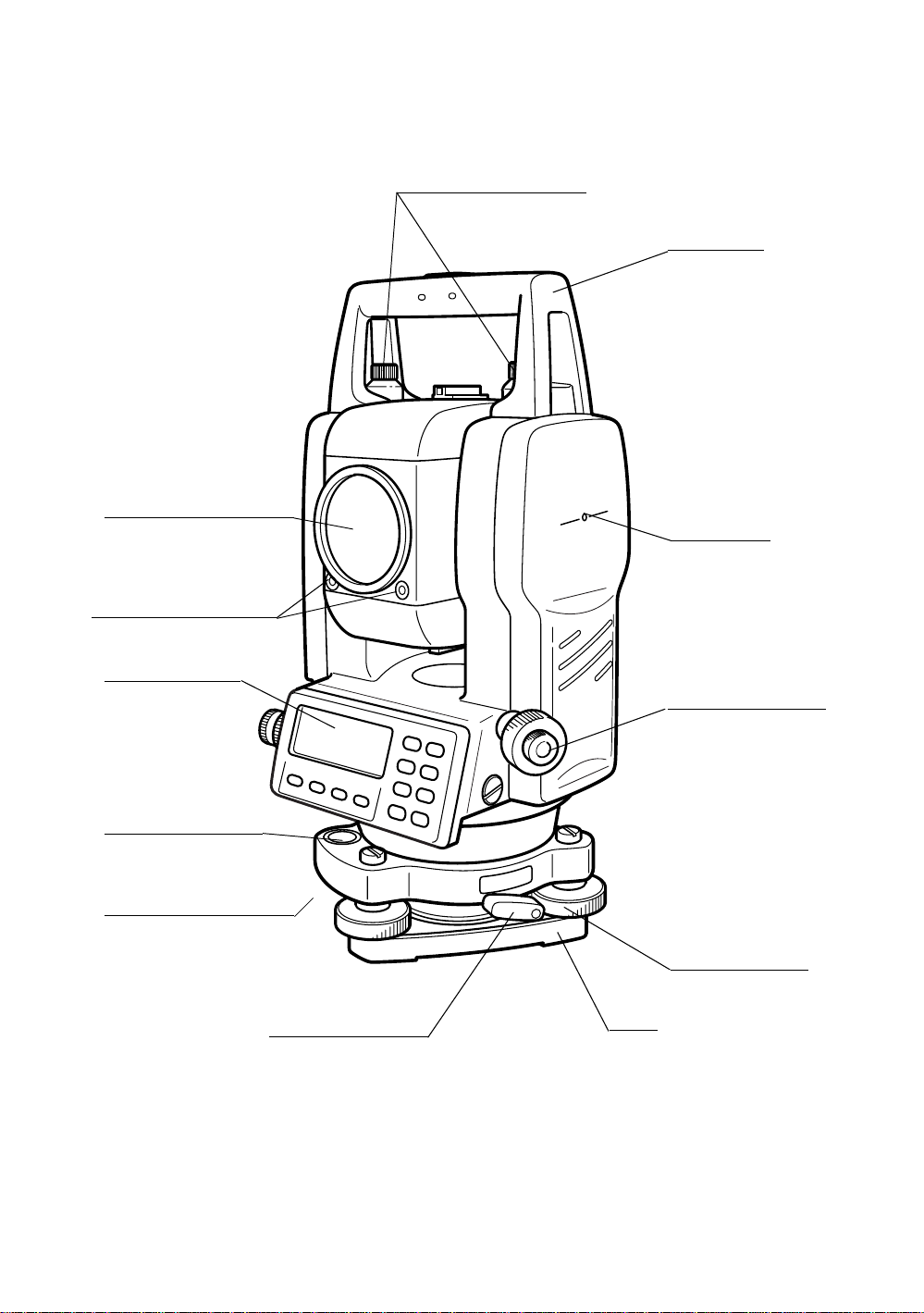
1.1 Nomenclature
Handgrip locking screw
Objective lens
Laser pointer
Laser aperture
Handgrip
Instrument
center ma rk
Point guide
Displa y uni t
(Only for
GPT-3002W/3003W/
3005W)
Circular level
Adjustment screw
for circular level
Tribrach fixing lever
Optical plummet
telescope
(Optical plummet
telescope type only)
Lev eling screw
Base
1-1
Page 13
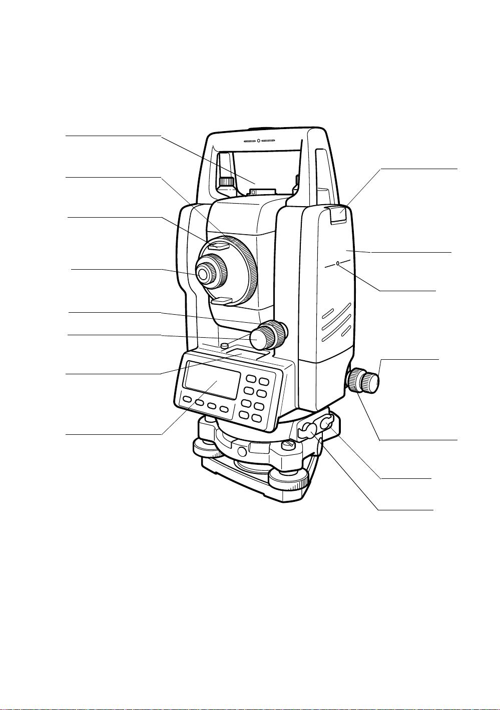
Sighting collimator
er
1 NOMENCLATURE AND FUNCTIONS
Telescope focusin g knob
Telescope gr i p
Telescope eye piece
*Vertical motion clamp
*Vertical tangent screw
Plate level
Display unit
Battery locking lev
On-board battery
BT-52QA
Instrument
center mark
Horizontal
tangent screw
Horizontal
motion clamp
Power supply
connector
Serial Signal
connector
*The position of vertical motion clamp and Vertical tangent screw will differ depending on the market.
1-2
Page 14
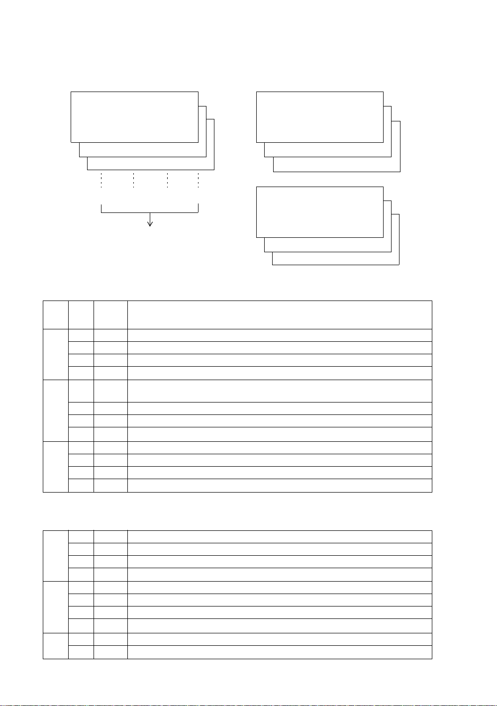
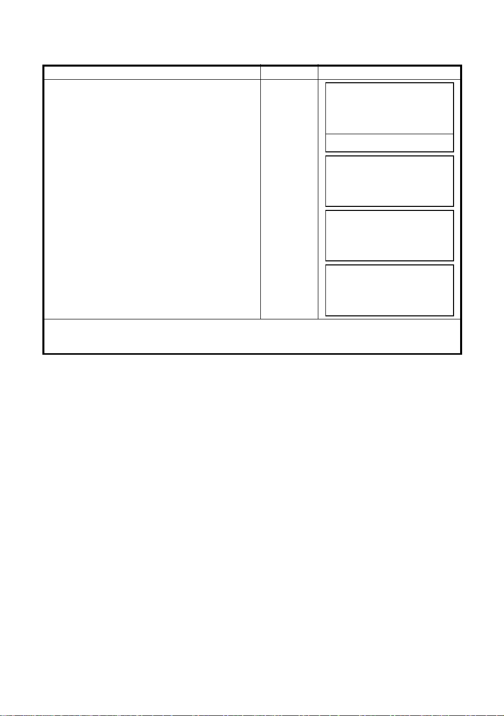
1.2 Display
● Display
The display uses a graphic LCD which has 4 lines and 20 characters per line. In general, the upper
three li nes display measured data, and the bottom line disp l a ys the soft key function whi ch changes
with the measuring mode.
● Contrast and Illumination
The contrast and illumination of display window are adjusted. See Chapter 6 “SPECIAL MODE
(Menu Mode)” or section 1.5 “Star key mode”.
● Example
1 NOMENCLATURE AND FUNCTIONS
V : 90°10'20"
HR: 120°30'40"
HR: 120°30'40"
HD* 65.432 m
VD: 12.345 m
0SET HOLD HSET P1
Angle measure me nt mode
V-angle : 90°10’20”
H-angle : 120°30’40”
Feet unit
HR: 120°30'40"
HD* 123.45 f
VD: 12.34 f
MEAS MODE NP/P P1
Horizontal-angle : 120°30’40”
Horizontal distance : 123.45ft
Relative elevation : 12.34ft
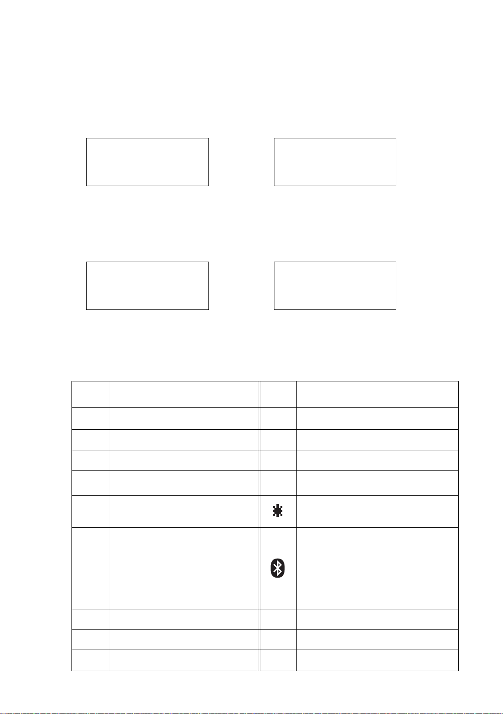
● Display marks
Display Contents Display Content
V V-angle
↓
MEAS MODE NP/P P1
Distance measurement mode
Horizontal-angle :120°30’40”
Horizontal distance : 65.432m
Relative elevation :12.345m
Feet and inch unit
HR: 120°30'40"
HD* 123.04.6f
VD: 12.03.4f
↓
MEAS MODE NP/P P1
Horizontal-angle : 120°30’40”
Horizontal distance : 123ft4in6/8in
Relative el ev at io n : 12ft3in4/8i n
✻
EDM working
↓
↓
HR H-angle right m Meter unit
HL H-angle lef t f Feet uni t / Feet and inch unit
N
HD Horizontal distance
VD Relative elevation Laser emitting mark
SD Slope distance
N N coordinate
E E coordinate
Z Z coordinate
Switches non-prism mode or prism mode
P
Bluetooth
communication.
(This symbol mark of the Bluetooth ™ will
be displayed above the battery mark when
the pulse total station is in the state which
can be communicated by Bluetooth™.)
™
is under
1-3
Page 15
1 NOMENCLATURE AND FUNCTIONS
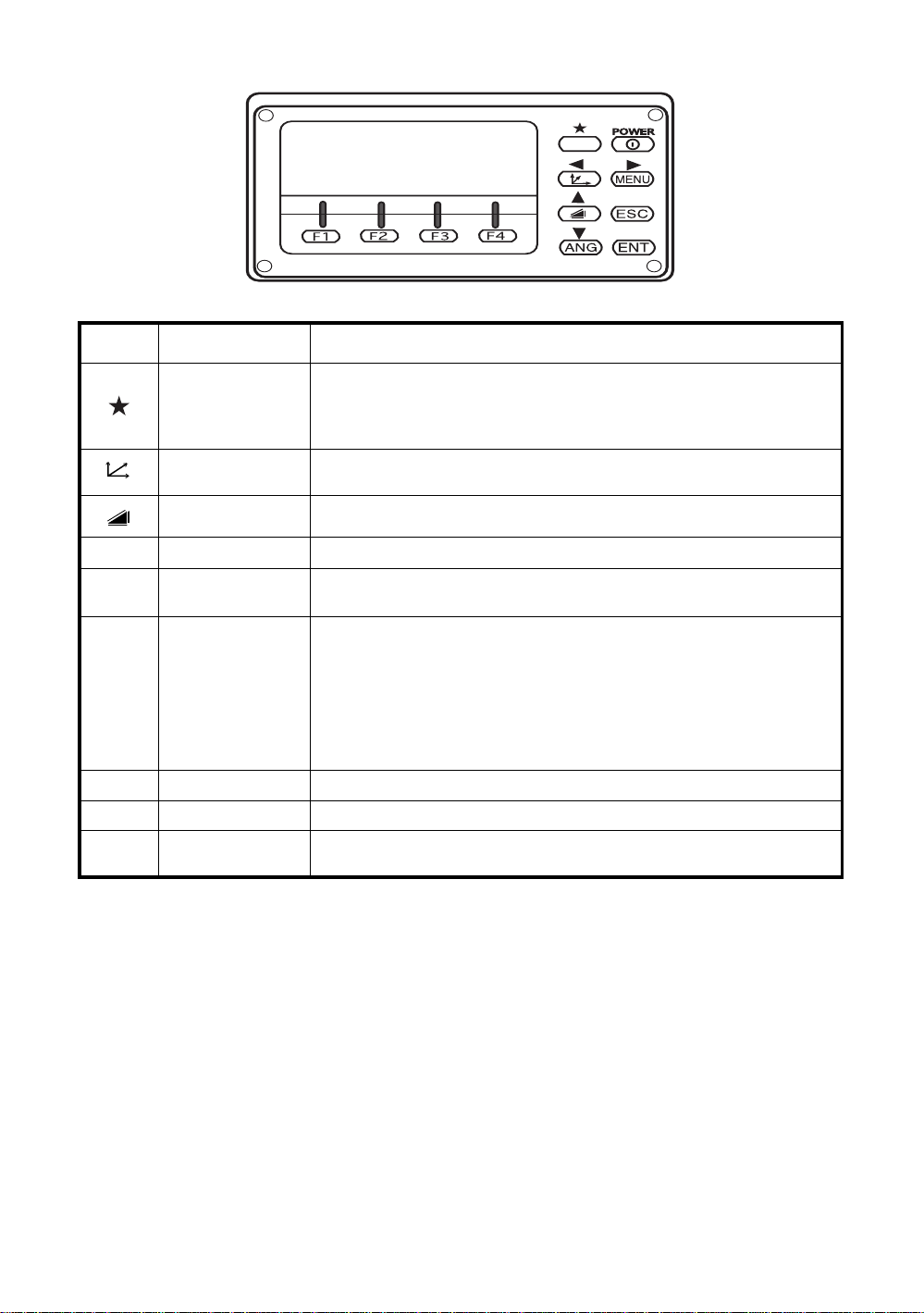
1.3 Operat ing Key
Keys Name of Key Funct ion
Star key mode is used f or each presetting or di splaying as follows.
Star key
Coordinate
meas.key
Distance meas.key Distance measurement mode
ANG Angle meas.key Angle measurement mode
MENU Menu key
1 Contrast of t he display 2 R e ticle illumina tion 3 Back Light
4 Non-prism/Prism 5 Laser poi nter 6 Laser plummet ( Laser plummet
type only) 7 Tilt correction 8 Point guide 9 Set audio mode
Coordinate measurement mode
To be menu mode. To set applic a t ion measur emen ts and adju s t i n the
menu mode.
● Returning to the mea sur ement mode or pre vious layer mode from the
mode set .
ESC Escape key
ENT Enter key Press at the end of inputting values.
POWER Power sour ce key ON/OFF of power source
F1–F4
Soft key
( Function key)
● To be DATA COLLECT ION mode or LAYOUT mode directly from the
normal measurement mode.
● It is also possible to use as Record key in normal measurement mode.
To select func ti on of Esc ape key,
see Chapter 16 “SE LEC TI N G MODE” .
Responds to the message displayed.
1-4
Page 16
1 NOMENCLATURE AND FUNCTIONS
1.4 Function Key (Soft Ke y)
The Soft Key message is displayed at the bottom line of display. The functions are according to the
displayed message.
Angle measurement mode Distance measurement mode
V: 90°10'20"
HR:120°30'40"
0SET HOLD HSET P1
TILT REP V% P2
H-BZ R/L CMPS P3
[F1] [F2] [F3] [F4]
Soft keys
Angle measurement
Soft
Page
1
2
3
Display
key
mark
F1 0SET Angle of Horizontal is set to 0°00'00"
F2 HOLD Hold the horizontal angle.
F3 HSET Sets a requi r ed horizontal a ngl e by ent eri ng numeral s.
F4
F1 TILT
F2 REP Repetition angle measurement mode
F3 V% Vertical angle percent grade(%) mode
F4
F1 H-BZ Sets the buzzer sound for every horizontal angle 90°.
F2 R/L Switches R/L rotation of horizontal angle.
F3 CMPS Switches the COMPASS ON/OFF of ver tical angle.
F4
The fu nction o f soft keys i s shown on next page (P2).
P1
↓
Setting Tilt Correction
If ON, the display shows tilt correction value.
The fu nction o f soft keys i s shown on next page (P3).
P2
↓
The fu nction o f soft keys i s shown on next page (P1).
P3
↓
HR:120°30'40"
HD*[r] <<m
VD: m
↓
↓
↓
MEAS MODE NP/P P1
OFSET S.O S/A P2
--- m/f/i --- P3
Coordina t es meas ur eme nt mode
↓
↓
↓
N: 123.456 m
E: 34.567 m
Z: 78.912 m
MEAS MODE NP/P P1
R.HT INSHT OCC P2
OFSET m/f/i S/A P3
Function
↓
↓
↓
Distance measurement mode
F1 MEAS Start measuring
F2 MODE Sets a measuring mode, Fine/Coarse/Tracking.
1
F3 NP/P Switches non-pris m mode or pri sm mode.
F4
F1 OFSET Select Off-set measurement mode.
F2 S.O Select stake out measurement mode.
2
F3 S/A Select set audio mode.
F4
F2 m/f/i Switches meter, feet or feet and inch unit.
3
F4
The fu nction o f soft keys i s shown on next page (P2).
P1
↓
The function of soft keys is shown on next page (P3).
P2
↓
The function of soft keys is shown on next page (P1).
P3
↓
1-5
Page 17

Coor di n ate measurem ent mo de
F1 M EAS Start measuri ng.
F2 MODE Sets a measuring mode, Fine/Coarse/Tracking.
1
F3 NP/P Switches non-pris m mode or pri sm mode.
F4
F1 R.HT Sets a prism height by input values.
F2 INSHT Sets an instrument height by input values.
2
F3 OCC Sets an instrument coordinate point by input values.
F4
F1 OFSET Select Off-set measurement mode.
F2 m/f/i Switches meter, feet or feet and inch unit.
3
F3 S/A Select set audio mode.
F4
The fu nction o f soft keys i s shown on next page (P2).
P1
↓
The function of soft keys is shown on next page (P3).
P2
↓
The function of soft keys is shown on next page (P1).
P3
↓
1 NOMENCLATURE AND FUNCTIONS
1-6
Page 18
1 NOMENCLATURE AND FUNCTIONS
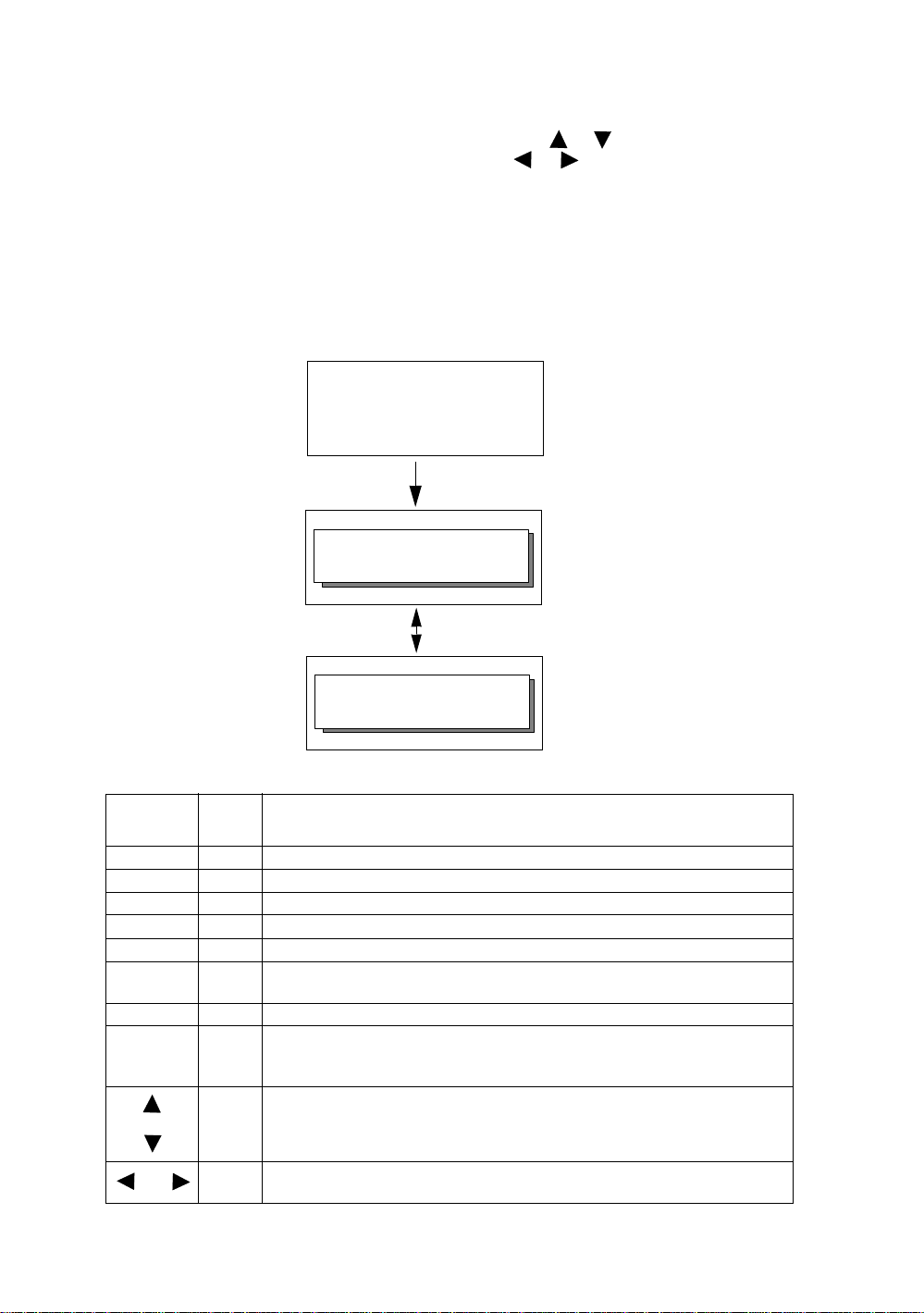
1.5 Star key mode
Press the (★) key t o vie w the inst rum ent options.
The following instrument options can be selected from the (★):
1.Adjustment the cont rast of the display (0 to 9 st eps) [or ]
2.Adjustment the reticle illumination (1 to 9 steps) [ or ]
3.Turn the backlight of the di splay, reticle illuminat i on ON / OFF
4.Select Non-prism mode / Prism mode
5.Turn the Laser pointer option ON /Bli n k/O FF
6. Tur n the Laser plummet option ON/OFF (Only for the laser plummet type)
7.Setting Tilt Correction
8.Turn the Point Guide option ON/OFF
9.S/A (set audio) mode
Note: Star k e y m ode do es not functio n when the same function as the func t io n assigned t o t he star key
mode is performed from the main routine.
V : 90°10'20"
HR : 20°30'40"
0SET HOLD HSET P1
Press the star (★) key.
↓
CONT:5 ↕ RTCL:5 ↔
B.LT NP/P L.P.L.PL
Press the star (★) key.
CONT:5 ↕ RTCL:5 ↔
--- TILT P.G. S/A
key
F1 B.LT Turn the backlight of the display, re ticle illumination ON/OFF
F2 NP/P Non-prism mode / Prism mode selection
F3 L.P. Turn the Laser pointer option ON / Blink / OFF
F4 L.PL Turn the Laser plummet option ON/OFF (Only for the laser plummet type)
F1 --- ----
F2 TILT
F3 P.G. Tu rn the Point Guide option ON/OFF
F4 S/A
Display
mark
Setting Tilt Correction
If ON, the display shows tilt correction value.
The light acceptance qua nti ty lev el for the E DM (S IGN AL), the atmos phe ric
correction value (PPM), the correction value of non-prism constant (NPM)
and correction value of prism constant (PSM) are displayed.
Function
or
or
CONT Adjust the contrast of the display (0 to 9 steps)
RTCL
Adjust the Reticle Illumination (1 to 9 steps)
ON/OFF of the ret i cl e ill um ination is linked with ON/ OF F of the bac klight.
1-7
Page 19

1 NOMENCLATURE AND FUNCTIONS
● Adju st ment th e cont r ast ( 0 to 9 ) of the displa y (CONT )
This enable you to adjust the contr ast of the d isp lay.
Press the up or down arrow keys to adjust the contrast.
● Adju stment the re ticle illumination (1 to 9 ) (RTCL)
This enable you to adjust the reticle illumination.
Press the right or left arrow keys to adjust the reticle illumination.
The switch of reticle illumination will be interlocked with the switch of display backlight.
● Turn the display backlight ON/OFF
To turn the bac k l ight ON, press the [F1] key. Press [F1] again to turn the back li gh t OFF.
● Switching the non-prism mode/prism mode
To switch the non -pri sm /p rism m ode , press the [F2](NP/P) key. Fo r mo re informatio n , see Chapter
4 “DISTANCE MEASUREMEN T” .
● Lighting, Blinking, and Extinguishing of Laser Pointer
Whenever the [F3] (L.P.) key is pressed, the laser pointer will light up, blink, or be extinguished, in
that order. The laser pointer assists wi th c ollimation by radiating visible laser light from the objective
lens to the target.
Laser aperture
● The laser pointer indicates the approximate collimation position of the telescope. It does not
indicate the exact collimation position. To adjust the laser pointer, see 17.2.2 “Checking the
optical axis of Laser pointer”.
● When the EDM is working, the laser pointer will blink.
● You cannot see the laser point er whe n looki ng through the tele scope . The ref ore , plea se loo k
directly, with the naked eye, at the point indicated by the laser pointer.
● The distance to which the laser pointer can be used will vary with climatic conditions and
with the eyesight of the user.
● When the laser pointer is used, the operating time of internal power source will become
short.
1-8
Page 20

1 NOMENCLATURE AND FUNCTIONS
● Tilt correction
The tilt setting mode performed here will not be memorized after powering OFF. To set TILT
correction in the initialized setting (it is memorized after powering OFF), see Section 6.4.3 “Ver tical
and Horizontal Angle Tilt correction ( Tilt ON/OFF)” .
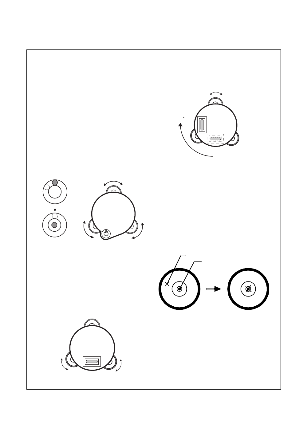
● Point guide
Fast and simple to use, the Point Guide feature is useful when doing stake out work. The Point
Guide System on the instrument telescope assist the rod person to get on-lin e. When using with the
Point Guide System, the operating time of internal power source will become short.
Turning the Point Guide ON and Operation:
Press the [F3] key to turn ON the Point Guide.
Looking at th e obj ective lens of the telescope, the right
LED will blink and the left LED will stay lit.
The Point Guide should be used wit hi n a distance of 100
meters (328 f e et). The qualit y of it s result s will depe nd on
the weather condi tions and the user
The goal of th e rod person is to look at both LED’s on the
instrument and move the prism on-line until both LED
are equally bright.
If the solid LED is brighter, move right.
If the blinking LED is brighter, move left.
Once you have determined that both of the LED's are equally bright, you are on-line with the
instrument.
Turning the Point Guide OFF:
To turn OFF the Point Guide System, press the [F3] key again.
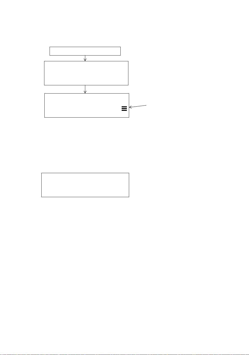
● Set audio mode
The light acceptance quantity level (Signal level) is displayed in this mode.
When reflected light from the prism is received, a buzzer sounds. Th i s functio n is good for easy
collimation when the target is difficult to find.
Press the [F4] key to view the set audio screen.
(1) To stop the buzzer , refer to Chapter 16 “SELECTIN G MODE”.
(2) Also, it is possible to display the signal level in Distance Measuring Mode.
s eyesight.
’
s
’
Illuminate
Instrument
Blink
Prism
The temperature, pressure, PPM, PSM and NPM can be viewed in set audio mode.
Refer to Chapter 10 “SET AUDIO MODE”, Chapter 11 “SETTING THE PRISM / NON-PRISM
CONSTANT VALUE” and Chapter 12 “ SETTING ATMO SPHERIC COR RECTION”, for furth e r
instructions.
1-9
Page 21

1 NOMENCLATURE AND FUNCTIONS
1.6 Serial signal RS-2 32C conn ecto r
The serial sig nal connector is used fo r co nnecting the GPT-3000W series with a comp uter or T OPCON
Data Collecto r , whi ch enab les t he compu ter to rece ive me asured dat a from the GPT-3000W series or to
send preset data of horizontal angle, etc. to it.
● The following data will be output at each mode.
Mode Output
Angle mode ( V,HR or HL) ( V in percent) V,HR (or HL)
Horizontal distance mode (HR, HD, VD) V,HR, HD, VD
Slope dista nce mo de (V, HR,SD) V,HR, SD,HD
Coordinate mode
● The display and the output at the coarse mode are the same as the contents above.
● Output at the tracking mode is displayed as distance data only.
The details necessary for the connection with the GPT-3000W series are obtained from its Interface
Manual which is optionally available. Please refer to the manual.
N, E, Z, HR (or V ,HR,SD,N,E,Z)
1.7 Bluetooth™ communication
By built-in Bluetooth, it can communicat e with DK-7W or ot her Bluetooth instr um ents by wireless ,
without connecting a serial signal connector.
1-10
Page 22
1 NOMENCLATURE AND FUNCTIONS
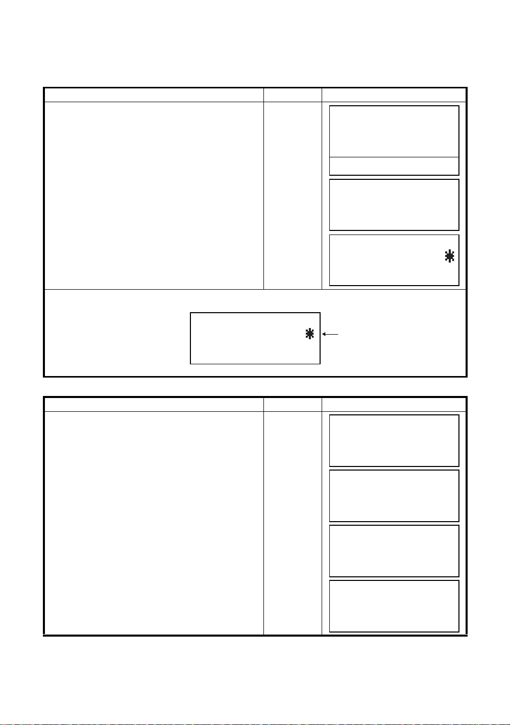
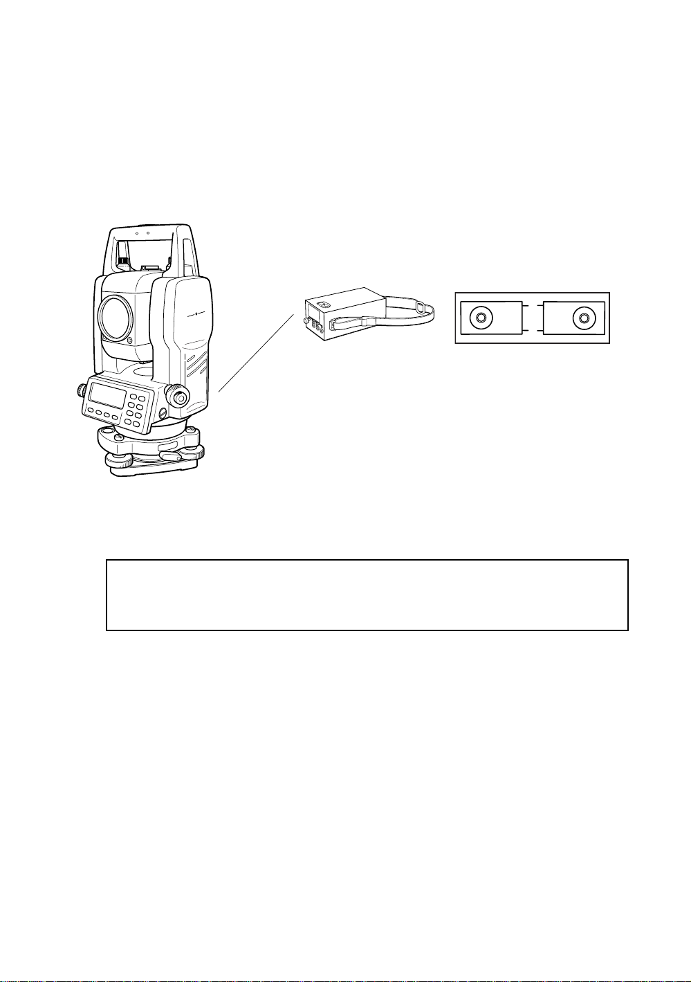
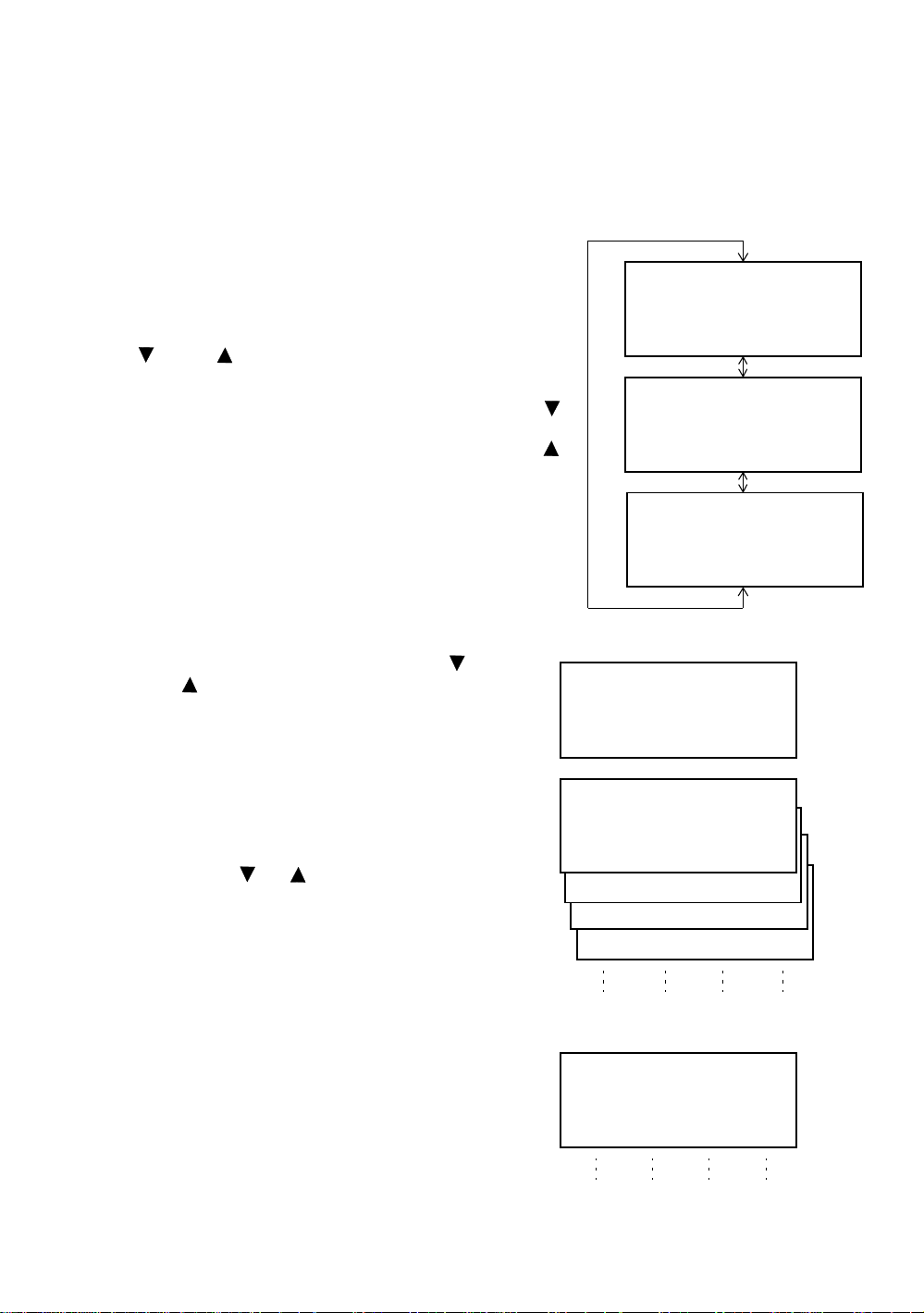
1.8 Laser Plummet ON/OFF (Only for Laser Plummet typ e)
Laser plummet option will help you to center the instrument easily onto the measurement point.
There are two ways to turn on/off of laser plummet option as follows.
● On/Off of lase r plumm et option by Soft Key in Tilt Cor rection
Operating procedure Option Display
Press the [F4] key to get the function page 2.
1
[F4]
V : 90°10'20"
HR: 120°30'40"
Press the [F1] (TILT) key.
2
In case ON is already select ed , th e display shows
tilt cor rection value.
Press the [F4] (L.PL) key.
3
By pressing the [F4](L.PL) key, the laser plummet
will be turned On / Off alternat ely.
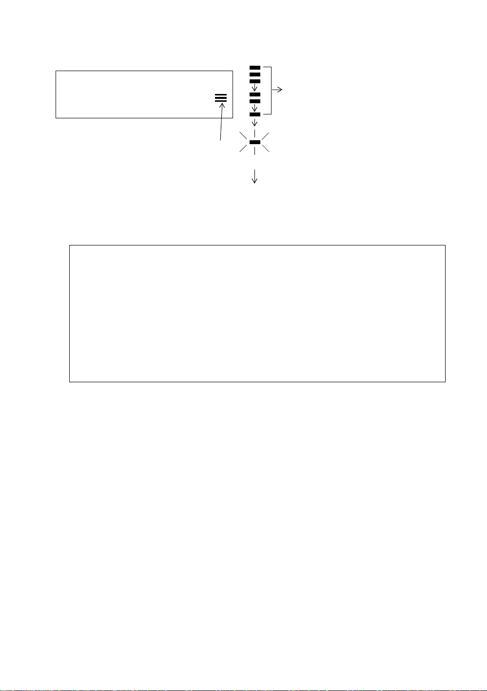
● Symbol mark while the laser is emitting.
The following symbol mark will appear at the right side of the second line.
[F1]
[F4]
TILT SENSOR:[XY-ON]
X:-0°00'25"
Y: 0°00'20"
X-ON XY-ON OFF L.PL
● On/Off of laser plumm et option from ME NU mode
Operating procedure Operation Display
Press the [MENU] key.
1
[MENU]
0SET HOLD HSET P1
TILT REP V% P2
TILT SENSOR:[XY-ON]
X:-0°00'25"
Y: 0°00'20"
X-ON XY-ON OFF L.PL
TILT SENSOR:[XY-ON]
X:-0°00'25"
Y: 0°00'20"
X-ON XY-ON OFF L.PL
Symbol mark
MENU 1/3
F1:DATA COLLECT
F2:LAYOUT
F3:MEMORY MGR. P
↓
↓
↓
Press the [F4] (P↓) key to get the menu on page 2.
2
[F4]
MENU 2/3
F1:PROGRAMS
F2:GRID FACTOR
↓
Press the [F3] k ey.
3
[F3]
F3:LASER PLUMMET P
LASER PLUMMET [OFF]
F1:ON
F2:OFF
Press the [ F1 ] or [F2] key to turn on or off the laser
4
plum m et opt ion.
[F1] or [F2]
LASER PLUMMET [ON]
F1:ON
F2:OFF
Laser Plummet auto-cut off function
The laser plummet will be turned off automatically after 1 to 99 minutes (Default :3 minutes). It is also
possible to stop the aut o-cut off functi on.
Refer to C hapter 16 “SELEC TING MODE” to change the time or to invalidat e the function.
1-11
Page 23
2 PREPARATION FOR MEASUREME NT
2 PREPARATION FOR MEASUREMENT
2.1 Power Connection
(unnecessary if on-board Ni-MH battery BT-52QA is used)
See below for connecting the external battery pack.
● Large cap acity battery pack BT-3L
Po w er cord PC-6 is used.
Battery pack
PC-6
BT-3L
Connector ends
PC-6
Note: BT-32Q on-board (Ni-Cd) battery can be al so available.
To use BT-32Q ( Ni- C d) ba t tery, it is required to change battery type in sel ecting mode, see
Section 6.4.5 “Selecting Battery Type”.
2-1
Page 24
2 PREPARATION FOR MEASUREME NT
Leveling screw C
9
2.2 Setting Instrument Up For Measurement
Mount the instrument to the tripod. Level and center the instrument precisely to insure the best
performance. Use tripods with a tripod screw of 5/8 in. diameter and 11 threads per inch, such as the
Type E TOPCON wide- frame wooden tripod.
Reference: Leveling and Centering the Instrument
1. Setting up the Tripod
First, extend the extension legs to suitable lengths
and tighten t he screws on their midsections.
2. Attaching the Instrument on the Tripod
Head
Place the instrument careful ly on the tripod head
and slide the instrument by loosening the tripod
screw. If the plumb bob is positioned right over the
center of th e point, slightly ti gh t en the trip od
screw.
3. Roughly Leveling the Instrument by Using
the Circular Level
1 Turn the leveling screws A and B to move the
bubble in the circular level. The bubble is now
located on a line perpendicular to a line
running thr ough the center s of the t wo le v e ling
screws bei ng adjusted.
Leveling
screw A
2 Turn the leveling screw C to bring the bubble
to the center of the cir c ular lev el .
4. Centering by Using the Plate Level
1 Rotate the instrument horizont ally by using
the Horizontal motion/clam p scr ew and place
the plate lev el par alle l with the line con necting
leveling screws A and B, and then bring the
bubble to the center of the plate level by
turning levelin g screws A and B.
Leveling screw B
Rotate the in strument 90° (10 0gon) arou nd its
2
vertical axis and turn the remaining leveling
screw or C to center the bubble once more.
Leveling screw C
0
90°
3 Repeat the procedures 1 and 2 for each 90°
(100gon) rot ation of the instrum ent and c hec k
whether the b ubb le is cor rectl y cente red for all
four p oin ts.
5. Centering by Using the Optical Plummet
Telescope
Adjust t he e y epiece of the optica l plumm et
telescope t o yo ur ey e si g ht .
Slide the instrument by loosening the tripod
screw, place the point on the center mark, and
then tighten the tripod screw. Sliding the
instrument carefully not to rotate that allows you
to get the least dislocation of the bubble.
Point
Center mark
6. Completely Leveling the Instrument
Lev eling the instrument pr ec isely in a similar wa y
to 4. Rotate the instrument and check to see that
the bubble is in the c enter of the plate level
regardless of telescope direction, then tighten the
Leveling
screw A
Leveling
screw B
tripod screw hard.
2-2
Page 25
2.3 Po wer Switch K ey ON
Confirm the instrument is leveled.
1
Press the pow er ke y.
2
Press the power key
TOPCON GPT-3000W
V : 90°10'20"
HR: 0°00'00"
2 PREPARATION FOR MEASUREME NT
Battery Power Rem aining Display
0SET HOLD HSET P1
● Confirm the battery power remaining display. Replace with charged battery or charge when battery
level is low or indicates “Battery empty”. see Section 2.4“Battery Power Remaining Display” .
● Contrast adjustment
You can confirm prism constant value (PSM), non - pri sm constant value (NPM), atm ospheric
correction value (PPM) and you can also adjust the contrast of the display when the instrument is
turned on.
To display this screen, see Chapter 16 “SELECT I NG MODE” .
↓
CONTRAST ADJUSTMENT
PSM: 0.0 PPM 0.0
NPM: 0.0
↓
↑ - - - ENTER
This enables you to adjust the brightness by pressing the [F1](
To memorize the setting value after powering off, press [F4](ENTER) key.
) or [F2](↑) key.
↓
2-3
Page 26
2.4 Battery Power Remaining Display
Battery power remaining display indicates the power condition.
V : 90°10'20"
HR: 0°00'00"
2 PREPARATION FOR MEASUREME NT
Measurement is possible.
0SET HOLD HSET P1
Battery power remaining display
Note: 1 The battery operating time will vary depending on the environmental conditions such as
ambient temperature, charging time, th e number of times of charging and discharging etc.
It is recommended for safety to charge the battery beforehand or to prepare spare full
charged batteries.
2 For general usage of the battery, see Chapter 14 “POWER SOURCE AND CHARGING” .
3 The battery power remaining display shows the power level regarding to the
measurement mode now operating.
The safety condition indicated by the battery power remai ning di s play in the angle
measurement mode does not nec essa ri ly assure the battery’s ability to be used in the
distance measurement mode.
It may happen that the mode change from the angle mode to the distance mode will stop
the operation because of insufficient battery power for the distance mode which
consumes more power than angle mode.
↓
The power is poor. The battery
should be recharged or replaced.
Blinking
<Battery empty>
Other displays disappear.
Measurement is imposs i b le.
Need to recharge or replace
the battery.
2-4
Page 27
2 PREPARATION FOR MEASUREME NT
g
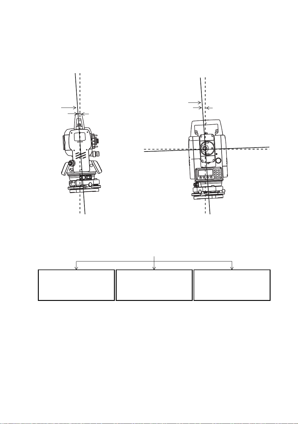
2.5 Vertical and Horizontal Angle Tilt Correction
(GPT-3007W has vertical angle tilt correction only.)
When the tilt sensors are activated, automatic correction of vertical and horizontal angle for
misle velment is displaye d.
To ensure a precise angle measurement, tilt sensors must be turned on. The display can also be used
to fine level the instrument. If the (TILT OVER) display appears the instrument is out of automatic
compensat ion range and must be leveled man ually.
Zenith
Zenith
Standing axis
Standing axis
Inclination of the standing
axis in the X direction
Inclination of the standin
axis in the Y direction
Horizontal
● GPT-3000W compensa t es both the vertic al an gl e and the horizon tal angl e readings due to
inclination of the standing axis in the X and Y directions .
● For more informati on about dual axis com pensation, re fer to APPEN DIX 1 “Dual Axis
Compensation”.
When the instrument is out of compensation. (TILT OVER)
V : ° ' "
HR: ° ' "
<X TILT OVER>
Standing Axis in the X direction
out of range
V : ° ' "
HR: ° ' "
<Y TILT OVER>
Standing Axis in the Y direction
out of range
V : ° ' "
HR: ° ' "
<XY TILT OVER>
Standing Axis in the X and Y
directions out of range
Trunnion ax i s
● The display of Vertical or Horizontal angl e i s unstable whe n instrument is on an un st able stage or a
windy day. You can turn off the auto tilt correction function of V/H angle in this case.
● To set auto tilt correct io n fr om the moment t hat power is on, see Section 6.4.3“V ertical and
Horizontal Angle Tilt correction ( Tilt ON/OFF)” .
2-5
Page 28
● Setting Tilt Correction by Soft Key
To enable you to select tilt ON/OFF function. setting is not memorized after power is OFF.
[Example] Setting X,Y Tilt OFF
Operating procedure Option Display
Press [F4] k ey to get t he functi on page 2.
1
2 PREPARATION FOR MEASUREME NT
[F4]
V : 90°10'20"
HR: 120°30'40"
0SET HOLD HSET P1
TILT REP V% P2
Press [F1](TILT) key.
2
In case ON is already select ed , th e display shows
tilt cor rection value.
[F1]
TILT SENSOR:[XY-ON]
X:-0°00'25"
Y: 0°00'20"
X-ON XY-ON OFF ---
Press [F3](OFF) ke y.
3
[F3]
TILT SENSOR: [OFF]
X-ON XY-ON OFF ---
Press [ESC] key.
4
[ESC]
V : 90°10'20"
HR: 120°30'40"
0SET HOLD HSET P1
● The setting mode performed here wil l not be memori z ed af ter powering OF F. To set TIL T cor rection in
the initialized setting ( it is memorized after powering OFF), see Section 6.4.3“Vertical and Horizontal
Angle Tilt corr ection ( Tilt ON/OFF) ” .
↓
↓
↓
2-6
Page 29
2 PREPARATION FOR MEASUREME NT
2.6 How to Enter Alphanumeric characters
This enables you to enter alphanumeric characters such as the instrument height, prism height,
occupied point, backsight point etc..
● How to select a item
[Exa mple se t t ing] Oc cupied point in the data collection mode.
The arrow indicates a item to enter.
PT# →ST-01
ID :
The arrow line moves up or down when the
[ ] key or [ ] key is pressed.
INS.HT: 0.000 m
INPUT SRCH REC OCNEZ
● How to enter characters
Move the arrow to enter a item using th e []
1
or [ ] key.
Press the [F1] (INPUT) ke y.
2
The arrow changes to the equal (=) .
The characters are displayed on the bottom
line.
Press the [ ] or [ ] key to select a page .
3
[]
or
[]
PT# :ST-01
ID
→
INS.HT: 0.000 m
INPUT SRCH REC OCNEZ
PT# :ST-01
ID :
→
INS.HT
0.000 m
INPUT SRCH REC OCNEZ
PT#
→
ID :
INS.HT: 0.000 m
INPUT SRCH REC OCNEZ
PT# =
ID :
INS.HT: 0.000 m
1234 5678 90.- [ENT]
ABCD EFGH IJKL [ENT]
MNOP QRST UVWX [ENT]
YZ+#[SPC][CLR][ENT]
Press the soft key to select a group of
4
characters.
Example: [F2](QRST) key is pressed.
[F1] [F 2] [F3] [F 4 ]
PT# =
ID :
INS.HT: 0.000 m
(Q) (R) (S) (T)
[F1] [F2] [F3] [F4]
2-7
Page 30

Press sof t key to select a charact er.
5
Example: [F4](T) key is pre sse d.
2 PREPARATION FOR MEASUREME NT
PT# =T
ID :
INS.HT: 0.000 m
MNOP QRST UVWX [ENT]
Select next character in the same manner.
PT# =TOPCON-1
ID :
INS.HT : 0.000 m
MNOP QRST UVWX [ENT]
Press [F4](ENT) key.
6
The arrow moves to next item.
Select next character in the same manner.
● To correct a character, move the cursor to correct c har acter by pressing [ ] or [ ] k ey and enter
again.
PT# :TOPCON-1
ID
→
INS.HT : 0.000 m
INPUT SRCH REC OCNEZ
2-8
Page 31

3 ANGLE MEASUREME NT
)
3 ANGLE MEASUREMENT
3.1 Measuring Hor izon tal An gle Righ t and Vertical Angle
Make sure the mode is in Angle measurement.
Operating procedure Operation Display
Collimate the 1st target (A).
1
Collimate A
V : 90°10'20"
HR: 120°30'40"
0SET HOLD HSET P1
Set horiz on tal angle of target A at 0° 00' 00".
2
Press the [F1](0 set) key and press the [F3](Y ES)
key .
[F1]
H ANGLE 0 SET
> OK?
--- --- [YES][NO]
[F3]
V : 90°10'20"
HR: 0°00'00"
0SET HOLD HSET P1
Collimate the 2nd target (B).
3
The required V/H angle to target B will be
displayed.
Collimate B
V : 98°36'20"
HR: 160°40'20"
0SET HOLD HSET P1
Reference : How to Collimate
1 Point the telescope toward the light. Turn the diopter ring and adjust the diopter so that the cross
hairs are clearly observed.
(Turn the diopter ring toward you first and then backward to focus.)
2 Aim the target at the peak of the t ri angle mark of the sighti ng collimator. Allow a certain space
between the sighting collimator and yourself for collimating.
Focus the target with the focusing knob.
3
↓
↓
↓
*If parallax is created between the cross
hairs and the targe t when viewing
vertically or hor iz ontally while looking
into the telescope, focusing is incorrect
or diopter adjustment is poor. This
adver sel y affects precision in
measurement or survey Eliminate the
parallax by carefully f oc usin g
and using diopter adjustment.
3-1
Åá
Åá
Focu sing knob
Telescope eyepiece (Diopter ring
Åá
Åá
Page 32

3.2 Switching Horizontal Angle Right/Left
Make sure the mode is Angle measurement.
Operating procedure Operation Display
Press the [F4] (↓) key twic e to get the f unction
1
on page 3.
twice
[F4]
3 ANGLE MEASUREME NT
V : 90°10'20"
HR: 120°30'40"
0SET HOLD HSET P1
TILT REP V% P2
H-BZ R/L CMPS P3
Press the [F2] (R/L) key.
2
The mode Horizontal angle Right (HR)
switc hes t o (HL) mod e .
[F2]
V : 90°10'20"
HL: 239°29'20"
H-BZ R/L CMPS P3
Measure as HL mode.
3
● Every time pressing the [F2] (R/L) key, HR/HL mode swi t ches.
3.3 Measuring from the Requir ed Horizontal A ngle
3.3.1 Setting by Holding the Angle
Make sure the mode is angle measurement.
Operating procedure Operation Display
Set the required ho rizon tal angle, using
1
Horizontal tangent screw
Display an gle
V : 90°10'20"
HR: 130°40'20"
0SET HOLD HSET P1
↓
↓
↓
↓
↓
Press the [F2] (HO LD) key.
2
Collimate the target.
3
Press the [F3](YES) key to finish holding the
4
horizontal angle.*1)
The display turns back to normal angle
measurement mode.
*1) To return to the previous mode, press the [F4](NO) key.
3-2
[F2]
Collimate
[F3]
H ANGLE HOLD
HR: 130°40'20"
> SET ?
--- --- [YES][NO]
V : 90°10'20"
HR: 130°40'20"
0SET HOLD HSET P1
↓
Page 33

3.3.2 Setting a Horizontal Angle from the Keys
Make sure the mode is Angle measurement.
Operating procedure Operation Display
Collimate the target.
1
Collimate
3 ANGLE MEASUREME NT
V : 90°10'20"
HR: 170°30'20"
0SET HOLD HSET P1
Press the [F3] (HS ET) key.
2
[F3]
H ANGLE SET
HR:
INPUT --- --- ENTER
1234 5678 90.-[ENT]
Input the required horizontal angle by
3
using ke ys . *1)
For example :70° 40'20"
When completed, normal measuring from the
required Horizontal angle is possible.
*1) To enter Alphanumeric cha racters, see Section 2.6 “How to Enter Alphanumeric characters” .
[F1]
70.4020
[F4]
V : 90°10'20"
HR: 70°40'20"
0SET HOLD HSET P1
3.4 Vertical Angle Percent Grade(%) Mode
Make sure the mode is Angle measurement.
Operating procedure Operation Display
Press the [F4](↓) key to get t he function on pag e 2.
1
[F4]
V : 90°10'20"
HR: 170°30'20"
0SET HOLD HSET P1
↓
↓
↓
TILT REP V% P2
Press the [F3] (V% ) ke y. *1)
2
[F3]
V : -0.30 %
HR: 170°30'20"
TILT REP V% P2
*1) Every tim e pressing the [F 3] (V%) key, the disp lay mode swi tches.
● When the measurement is carried out over ±45° (±100%) from the horizontal, the displ a y shows
<OVER>.
3-3
↓
↓
Page 34

3 ANGLE MEASUREME NT
3.5 Repetition Angle Measurement
● Repetiti on angle measuremen t can be done by horizontal angle right measurement mode.
Make sure the mode is Horizontal Angle Right measurement.
Operating procedure Operation Display
Press the [F4](↓) key to get t he function on pag e 2.
1
[F4]
V : 90°10'20"
HR: 170°30'20"
Press the [F2] (RE P)key.
2
Press the [F3] (YE S) key.
3
Collimate the target A and press the [F1] (0SET)
4
key.
Press the [F3] (YE S) key.
5
Collimate the target B using the horizontal clamp
6
and tangent screw.
Press the [F4] (HO LD) key.
[F2]
[F3]
Collimate A
[F1]
[F3]
Collimate B
[F4]
0SET HOLD HSET P1
TILT REP V% P2
↓
↓
REPETITION ANGLE
> OK?
--- --- [YES][NO]
REP-ANGLE COUNT[ 0]
Ht: 0°00'00"
Hm:
0SET V/H REL HOLD
REPETITION ANGLE
INITIALIZE
> OK?
--- --- [YES][NO]
REP-ANGLE COUNT[ 0]
Ht: 0°00'00"
Hm:
0SET V/H REL HOLD
REP-ANGLE COUNT[ 1]
Ht: 45°10'00"
Hm: 45°10'00"
0SET V/H REL HOLD
Recolli ma t e tar get A using the hor i zontal clamp
7
and tangent screw, and press the [F3](REL)key.
Recolli ma t e tar get B using the hor i zontal clamp
8
and tangent screw, and press the [F4](HOLD) key.
Repeat 7 to 8 to measure the desired number of
9
repetitions.
3-4
Collimate A
[F3]
Collimate B
[F4]
REP-ANGLE COUNT[ 1]
Ht: 45°10'00"
Hm: 45°10'00"
0SET V/H REL HOLD
REP-ANGLE COUNT[ 2]
Ht: 90°20'00"
Hm: 45°10'00"
0SET V/H REL HOLD
REP-ANGLE COUNT[ 4]
Ht: 180°40'00"
Hm: 45°10'00"
0SET V/H REL HOLD
[Example] 4 measurement
Page 35

To return to the normal angle mode, press the
10
[F2](V/H) key or [ESC] key.
Press the [F3] (YE S) key.
11
[ESC]
or
[F2]
[F3]
3 ANGLE MEASUREME NT
REPETITION ANGLE
Exit
> OK?
--- --- [YES][NO]
V : 90°10'20"
HR: 170°30'20"
0SET HOLD HSET P1
● Horizontal angle can be accumulated up to
(3600°00'00" – minimum reading) (horizontal angle right).
In case of 5 second reading, horizontal angle can be accumulated up to +3599°59'55".
● Error will be displayed when the results differ from first measurement by more than ±30".
3.6 Buzzer Sounding for Horizontal Angle 90° Increments
When the horiz ontal angle f alls in the ra nge of less than ± 1° of 0°, 90°, 180° o r 270° , the buzzer
sounds. Buzzer stops only when the horizontal angle is adjusted to 0°00’00”, 90°00’00” , 180°00’00” or
270°00’00”.
This settin g is not memoriz ed after powering off. Refer to 16 “SELECTING MODE ” to set the init ial
setting (memorized after powering off).
Make sure the mode is Angle measurement.
Operating procedure Operation Display
Press the [F4] (↓) key twic e to get the f unction
1
on page 3.
Press the [F1] (H-B Z) k ey.
2
The data previously set is shown.
[F4]
twice
[F1]
V : 90°10'20"
HR: 170°30'20"
0SET HOLD HSET P1
H-BZ R/L CMPS P3
H-ANGLE BUZZER [OFF]
[ON] [OFF] --- ENTER
↓
↓
↓
Pres s the [F1](O N ) key or [F2](OF F ) key to select
3
the buzzer ON/ OFF.
Press the [F4] (EN TER ) ke y.
4
3-5
[F1] or [F2]
[F4]
H-ANGLE BUZZER [ON]
[ON] [OFF] --- ENTER
V : 90°10'20"
HR: 170°30'20"
0SET HOLD HSET P1
↓
Page 36

3.7 Compasses ( vertical angle)
LOCK
Vertical angle is displayed as shown below.
3 ANGLE MEASUREME NT
+90°
0°
LOCK
-90°
Operating procedure Operation Display
Press the [F4] (↓) key twic e to get the f unction
1
on page 3.
Press the [F3] (CM PS) key. *1)
2
[F4]
twice
[F3]
*1) Every time pressing the [F3](CMPS) key, the display mode switches.
0°
V : 98°10'20"
HR: 170°30'20"
0SET HOLD HSET P1
H-BZ R/L CMPS P3
V : - 8°10'20"
HR: 170°30'20"
H-BZ R/L CMPS P3
↓
↓
↓
3-6
Page 37

4 DISTANCE MEASUREMENT
4 DISTANCE MEASUREMENT
Note: Those distance shorter than 1m and 400m or more will not be displayed in Non-prism
mode.
● Prism mode and Non-prism mode
In GPT-3000W series, the distance measurement will b e done using invisible pulse laser beam emitted
from pulse lase r diode. You can sel ec t measuremen t mode between Prism mode whic h collimating a
prism and Non-prism mode that is collimating a target object except prism.
● Regardles s of whether the laser pointer is used, meas urem ent is possible with bot h the non - prism
mode and the prism mo d e. Tha t is, when the GPT-3000W is used in the open air, in an urban area,
etc., the laser pointer can be stopped and distance measurement then conducted, making it
possible to prevent the laser light from hitting a third party.
● When using a reflection sheet, measure with the prism mode.
● For measurement with a prism, be sure to measure with the prism mode. If you measure with the
non-prism mode, accuracy cannot be guaranteed.
● Non-prism mode enables all d ist ance measureme nt s such Distance measur ement, Coordinate
measurement, Offset measurement and Layout.
● To switch over Prism mode to N on-prism mode or contrary, press the [NP/P] sof t key in eac h
measurement display. [NP] of Non-prism mode indicator will be shown at the right corner of the
display in Non-prism mode measurement.
Changing mode shall be done before measurement.
Example
● It is possible to set Non-prism mode for distance measurement during the power on time. Refer to
● If happened collimating the near distance prism in Non-prism mode, measurement will not be done
Distance measurement mode
HR: 120°30'40"
HD* 65.432 m
VD: 12.345 m
MEAS MODE NP/P P1
To change the mode, press the [NP/P] soft key in each measurement.
16.SELECTING MODE to set the option.
because of too much light.
N
P
↓
Non-prism
mode
indicator
Coordinate measurement mode
N: 120.456 m
E: 34.567 m
N
Z: 12.345 m
MEAS MODE NP/P P1
P
↓
4.1 Setting of the Atmospheric Correction
When setting the atmospheric correction, obtain the correction value by measuring the temperature
and pressure. Refer to Section 12.2 “Setting of Atmospheric Correction Value”.
4.2 Setting of the Correction for Prism C o nstant / N on-prism Co nstant
Topcon’s p rism co nstant value is 0. Set correction for prism at 0. If the prism is of anothe r manufacture,
the appropriate constant shall be set beforehand. Refer to Chapter 11 “SETTING THE PRISM / NONPRISM CONSTANT V AL UE ”. The setting value is kept in the memory ev e n after po w er is off.
Note: Confirm that Non-pri sm cor rec t ion value is set at zer o before measurem ent target such
as a wall in Non-prism mode.
4-1
Page 38

4 DISTANCE MEASUREMENT
4.3 Distance Measur eme nt (Con tin u ou s Measur em ent )
Make sure the mode displays angle measurement.
Operating procedure Operation Display
Collimate the center of prism.
1
Collimate P
V : 90°10'20"
HR: 120°30'40"
↓
Press the [ ] key.
2
Distance measurement starts. *1),2)
[ ]
0SET HOLD HSET P1
HR: 120°30'40"
HD*[r] << m
VD: m
↓
The measured distances are shown. *3)~*5)
MEAS MODE NP/P P1
HR: 120°30'40"
HD* 123.456 m
VD: 5.678 m
MEAS MODE NP/P P1
● Pressing the [ ] key again, the display
changes to horizontal (HR) and ver tical (V)angle
and slope distance(SD). *6)
*1) When EDM is working, the "✻ " mark appears in the display.
*2) To change mode from Fine to Coa rse or Tracki ng, refer to secti on 4.5 “Fine Mode/Tracking Mo de/
Coarse Mode”.
To set the distance measurement on when the i nstrument is power ed on, refer t o Chapter 16
“SELECTING MODE”.
*3) Th e distance unit indi cator "m" (f or met er) , "f" (for f ee t or feet inch) app ears and disa ppe ars alterna tive ly
with buzzer sounds at every renewal of distance data.
*4) Measurement may repeat automatica l ly in the instru ment if the resu l t is affected by shim me r etc. .
*5) To return to the normal measuring angle mode from a distance measuring mode, press the [ANG] key.
*6) It i s possible to choose the display ord er (HR, HD, VD) or (V, HR, SD) fo r ini ti al measuring distance
mode. Refer to Chapter 16 “SELECTING MODE” .
[ ]
V : 90°10'20"
HR: 120°30'40"
SD* 131.678 m
MEAS MODE NP/P P1
↓
↓
4-2
Page 39

4 DISTANCE MEASUREMENT
4.4 Distance Measur eme nt
When the number of time s meas urem ent is preset, the GPT-3000W series measures the dis ta nce the
set number of times. The average distance will be displayed.
When presetting the number of times as 1, it does not display the average distance, because of single
measurement . Si n gl e mea sure me nt is set at the factory.
Make sure the mode displays angle measurement.
Operating procedure Operation Display
Collimate the center of prism.
1
(N-time Measurement/Single Measurement)
V : 90°10'20"
HR: 120°30'40"
0SET HOLD HSET P1
Press the [ ] key.
2
Continuous measuring starts.*1)
[ ]
HR: 120°30'40"
HD*[r] << m
VD: m
MEAS MODE NP/P P1
Press [F1]( ME AS) key while continuous
3
meas uring i s exceedin g. * 2)
The average value is displayed and "*" mark
disappears.
● While EDM is working, press [F1](MEAS) key
again, the mode will be changed to continuous
measuring mode.
[F1]
HR: 120°30'40"
HD*[n] << m
VD: m
MEAS MODE NP/P P1
HR: 120°30'40"
HD: 123.456 m
VD: 5.678 m
MEAS MODE NP/P P1
↓
↓
↓
↓
*1) It i s possi bl e to set the measu rement mode f or N- times me asurem ent mode or co ntinuo u s measurement
mode when the power is turned on. Refer to Chapter 16 “SELECTING MODE”.
*2) For setting the number of times (N-times) in the measurement, refer to Chapter 16 “SELECTING
MODE”.
4-3
Page 40

4 DISTANCE MEASUREMENT
● Choose meter /f eet / feet+inch uni t by soft ke y
It is possible to change the unit for distance measurement mode by soft key.
This setting is not memorized after power off. Ref er to 16 “SELECTING MODE” to set at the initial
setting (memorized after power off).
Operating procedure Operation Display
Press the [F4] (P1↓) key twice to get the function
1
on page 3.
[F4]
HR: 120°30'40"
HD* 2.000 m
VD: 3.000 m
MEAS MODE NP/P P1
↓
OFSET S.O S/A P2
--- m/f/i --- P3
Press the [F2](m/f/i) key, the display unit will be
2
changed.
● Every time pressin g the [F2 ](m /f/i) key, the unit
mode swi tche s.
[F2]
HR: 120°30'40"
HD* 6.560 f
VD: 9.845 f
--- m/f/i --- P3
4.5 Fine Mode/Tracking Mode/Coarse Mode
This setting is not memorized after power is off. Refer to Chapter 16”SELECTING MODE” to set at the
initial set ting (memorized after power is off).
•Fine Mode : This is a normal distance measuring mode.
The unit to be displayed can be changed.
Measurement time will vary depending on the unit to be displayed.
•Tracking Mode : This mode measures in shorter time than in fine mode.
It is very useful when tailing the moving object or carrying out stake-out work.
•Coarse Mode : This mode measures in shorter time than in fine mode.
The unit to be displayed can be changed.
To change the unit to be d isp layed in fine mode, see Chapter 16 “SELECTING MODE” and to change
the unit in course mode, see section 6.4.1 “Setting Minimum Reading”.
For the details of the unit and measurement time in each mode, see Chapter 23 “SPECIFIC ATIONS” .
↓
↓
↓
Operating procedure Operation Display
Press the [F2] (MO DE ) ke y f rom the dis t anc e
1
measuring mode.*1)
The initial character (F/T/C) of set mode is
displayed . (F:Fine, T:Tracking, C:Coarse)
Press the [F1] (FINE) key, [F2](TRACK ) key, or
2
[F3](C O AR SE) key.
*1) To cancel the setting, press the [ESC] key.
4-4
[F2]
[F1]~[F3]
HR: 120°30'40"
HD* 123.456m
VD: 5.678m
MEAS MODE NP/P P1
HR: 120°30'40"
HD* 123.456m
VD: 5.678m
FINE TRACK COARSE F
HR: 120°30'40"
HD* 123.456m
VD: 5.678m
MEAS MODE NP/P P1
↓
↓
Page 41

4 DISTANCE MEASUREMENT
4.6 Stake Out (S.O)
The difference between the measured distance and the input stake out distance is displayed.
Measured distance — Stake out distance = Displayed value
● In stake out operati on, you can select either horizontal distance (HD), relative el evati on (V D) and
slope distance (SD)
Operating procedure Operation Display
Press the [F4] (↓) key in the dista nce me asu ring
1
mode to get the function on page 2.
[F4]
HR: 120°30'40"
HD* 123.456 m
VD: 5.678 m
MEAS MODE NP/P P1
↓
Press the [F2] (S . O ) ke y.
2
The data previously set is shown.
Select th e measuring mode by pre ssin g the [F1] to
3
[F3] key.
Example : Horizontal dist ance
Ente r th e dist ance for stake ou t. *1)
4
Collimate the target (Prism).
5
Measuring starts.
The difference between the measured distance
and the stake out distance is displayed.
Move the target until the difference becomes 0m.
6
[F2]
[F1]
[F1]
Enter data
[F4]
Collimate P
OFSET S.O S/A P2
STAKE OUT
HD : 0.000 m
HD VD SD ---
STAKE OUT
HD : 0.000 m
INPUT --- --- ENTER
1234 5678 90.-[ENT]
STAKE OUT
HD : 100.000 m
INPUT --- --- ENTER
HR: 120°30'40"
dHD*[r] << m
VD: m
MEAS MODE NP/P P1
HR: 120°30'40"
dHD* 23.456 m
VD: 5.678 m
MEAS MODE NP/P P1
↓
↓
↓
*1) Refer to section 2.6 “How to Enter Alphanumeric characters”.
● To return to normal distance measurement mode, stake out distance to "0" or turn the power off.
4-5
Page 42

4 DISTANCE MEASUREMENT
4.7 Offset Measurement
There are four offset measurement mode s in the Offs et Meas urem en t .
● Angle offse t
● Distance offset
● Plane offse t
● Column offset
To show the offset measurement menu, press the [OFSET] soft key from distance or coordinate
measurement mode.
Example:
Distance measurement
HR: 120°30'40"
HD: 123.456 m
VD: 5.678 m
MEAS MODE NP/P P1
OFSET S.O S/A P2
Press the [F1](OFSET) key.
↓
↓
Coordinate measurement
N: 123.456 m
E: 34.567 m
Z: 78.912 m
MEAS MODE NP/P P1
R.HT INSHT OCC P2
OFSET m/f/i S/A P3
Press the [F1](OFSET) key.
↓
↓
↓
Offset Measurement Menu
OFFSET 1/2
F1:ANG.OFFSET
F2:DIST.OFFSET
F3:PLANE OFFSET P
[F4]
↓
OFFSET 2/2
F1:COLUMN OFFSET
P
↓
● Outputting the Measurement Data
The results of offset measurement can be output to external device.
Setting the function of th e [ESC] key to (RE C) , the [F3] soft key wh ich assigned (REC) will appear in
measured result display.
Refer to Chapter 16 “SELECTING MODE” to set this option.
OFFSET-MEASUREMENT
HR: 120°30'40"
SD: 123.456 m
NEXT --- REC ---
[F3]
● Distance measurement mode of the offset measurement
Offset measurement will be done by N-time fine measurement mode.
For setting measuring times refer to Chapter 16 “SELECTING MODE”.
4-6
Page 43

4 DISTANCE MEASUREMENT
4.7.1 Angle Offset
This mode is useful when it is difficult to set up the prism directly, for example at the center of a tree.
Place the prism at the same horizontal distance from the instrument as that of point A0 to measure.
To measure the coordinates of the center position, operate the offset measurement after setting the
instrument height/prism height.
When measuring coordinates of ground point A
:Set the inst rumen t height/prism height.
When measuring coordinates of point A
Prism P
Prism height
Instrument height
Occ. Point
● Set the instrument height/prism height before proceeding to the offset measurement mode.
● When setting the coordinat e v al ue f or the occupied stat io n, refer to Section 5.1 “Set ting Coordinate
V alues of Occupied Point”.
the instrument height only. (Set t he prism hei ght
to 0 ).
When sighti ng to A
ways. One is to fix v ertical angle to the prism
positi on e ven updown the telescope posit i on, and
the other is to gear vertical angle to the updown of
telescope movement. In case following the
vertical angle to the movement of telescope,
SD(Slope Distance) and VD(Vertical Distance)
will be changed according to the movement of
telescope.
To set this option, refer to Chapter 16
“SELECTING MODE ”.
, you can select one of two
0
: Set
0
1
Operating procedure Operation Display
Press the [F4] (P1↓) key from distance measuring
1
mode to get the function on page 2.
Press the [F1] (OF SET) key.
2
Press the [F1](ANG. OFFSET) key.
3
Collimate prism P, and press the [F1](MEAS) key.
4
[F4]
[F1]
[F1]
Collimate P
[F1]
HR: 120°30'40"
HD: 123.456 m
VD: 5.678 m
MEAS MODE NP/P P1
OFSET S.O S/A P2
OFFSET 1/2
F1:ANG.OFFSET
F2:DIST.OFFSET
F3:PLANE OFFSET P1
OFFSET-MEASUREMENT
HR: 120°30'40"
HD: m
MEAS --- NP/P ---
OFFSET-MEASUREMENT
HR: 110°20'30"
HD* [n] << m
>Measuring...
↓
↓
↓
4-7
Page 44

4 DISTANCE MEASUREMENT
The horizontal distance from the instrument to the
prism will be measured.
OFFSET-MEASUREMENT
HR: 110°20'30"
HD: 56.789 m
NEXT --- --- ---
Collimate point A0 using the horizontal motion
5
clamp and hori zontal tang ent s cr ew.
Collimate
A
0
OFFSET-MEASUREMENT
HR: 113°30'50"
HD: 56.789 m
NEXT --- --- ---
Show t he rela t i ve eleva t ion of point A0.
6
[ ]
OFFSET-MEASUREMENT
HR: 113°20'30"
VD: 3.456 m
NEXT --- --- ---
Show the slope distance of point A0.
7
[ ]
● Each time pressing the [ ] key, horizontal
distance, relative elevation and slope distance are
shown in sequence.
Show N coordinate of point A0 or A1.
8
● Each time pressing [ ] key, N,E and Z
coordinate are show n in sequence.
● To return to procedure
● To return to the previous mode, press the [ESC] key.
● To select the Non-prism or Prism mode, press the [F3](NP/P) key after the step
, press the [F1](NEXT) key.
4
[]
OFFSET-MEASUREMENT
HR: 113°20'30"
SD: 56.894 m
NEXT --- --- ---
OFFSET-MEASUREMENT
HR: 113°20'30"
N : -12.345 m
NEXT --- --- ---
.
3
4-8
Page 45

4 DISTANCE MEASUREMENT
4.7.2 Distance Offset Measurement
Measuring distance and coordinate of the center of a pond or a tree of which the radius is known.
Measuring the di st ance or co ordinate till P0 point, input
point showing as following draw in distance offset measurement. The display shows distance or
coordinate value until P0 point.
P0
oHD val ue as an of fset value and measu r e P1
P1
P1
oHD >0
In case the mea suring point of (P1) is front side than that of requiring
point of (P0), t he off s et value shall be plus, and if it is rear si d e, the
offset va lue shall be minus.
Occ. Point
● When setting the coordinat e v al ue f or the occupied stat io n, refer to Section 5.1 “Set ting Coordinate
V alues of Occupied Point”.
Operating procedure Operation Display
Press the [F4] (P1↓) key from distance measuring
1
mode to get the function on page 2.
[F4]
oHD < 0
HR: 120°30'40"
HD: 123.456 m
VD: 5.678 m
MEAS MODE NP/P P1
OFSET S.O S/A P2
Press the [F1] (OF SET) key.
2
[F1]
OFFSET 1/2
F1:ANG.OFFSET
F2:DIST.OFFSET
F3:PLANE OFFSET P
↓
↓
↓
Press the [F2](DIST. OFFSET) key.
3
Press the [F1] (INP UT ) ke y and enter a offset
4
value, and press the [F4](E N TER) key.
Collimate prism P1, and press the [F1](MEAS)
5
key.
Measuring will start.
4-9
[F2]
[F1]
Offset
value
[F4]
Collimate
P1
[F1]
DISTANCE OFFSET
INPUT FORWARD HD
oHD: m
INPUT --- --- ENTER
DISTANCE OFFSET
HR: 80°30'40"
HD: m
MEAS --- NP/P ---
DISTANCE OFFSET
HR: 80°30'40"
HD* [n] << m
>Measuring...
Page 46

4 DISTANCE MEASUREMENT
After measuring, the result added offset value will
be show n.
DISTANCE OFFSET
HR: 80°30'40"
HD* 10.000 m
NEXT --- --- ---
Show t he rela t i ve eleva t ion of point P0.
6
● Each time pressing the [ ] key, horizontal
distance, relative elevation and slope distance are
shown in sequence.
[ ]
DISTANCE OFFSET
HR: 80°30'40"
VD: 11.789 m
NEXT --- --- ---
DISTANCE OFFSET
HR: 80°30'40"
SD: 11.789 m
NEXT --- --- ---
● Show coordinate of point P0.
[]
N : 12.345 m
E : 23.345 m
Z : 1.345 m
NEXT --- --- ---
, press [F1](NEXT) key.
● To return to procedure
● To return to the previous mode, press [ESC] key.
● To select the Non-prism or Prism mode, press the [F3](NP/P) key after the step 4.
4
4-10
Page 47

4 DISTANCE MEASUREMENT
4.7.3 Plane Offset Measurement
Measuring will be taken for the place where direct measuring can not be done, for example distance or
coordinate measuring for a edge of a plane.
Three random prism points (P1, P2, P3) on a plane will be measured at first in the plane offset
measurement to determine the measured plane. Collimate the measuring target point (P0) then the
instrument ca lc ulates and displays coordinate and distance value of cross point between collimation
axis and of the plane.
Edge
P
3
P
● When setting the coordinat e v al ue f or the occupied stat io n, refer to Section 5.1 “Set ting Coordinate
V alues of Occupied Point”.
Example: Non - pr i sm measurement
Operating procedure Operation Display
Press the [F4] (P1↓) key from distance measuring
1
mode to get the function on page 2.
P
2
P
Target heights of P1 to P3 is set to zero automatically.
[F4]
HR: 120°30'40"
HD: 123.456 m
VD: 5.678 m
MEAS MODE NP/P P1
OFSET S.O S/A P2
↓
↓
Press the [F1] (OF SET) key.
2
Press the [F3] (PLA NE OF FSE T) ke y.
3
Press the [F3] (NP /P) k e y to cha nge to the non-
4
prism mode.
Collimate first point P1, and press the [F1](MEAS)
5
key.
N-time measuring will start.
After measur ing, the disp l ay will show the second
point measurement.
4-11
[F1]
[F3]
[F3]
Collimate
P1
[F1]
OFFSET 1/2
F1:ANG.OFFSET
F2:DIST.OFFSET
F3:PLANE OFFSET P
PLANE
N001#:
SD: m
MEAS --- NP/P ---
PLANE
N001#:
N
SD: m
MEAS --- NP/P ---
PLANE
N001#:
N
SD* [n] << m
>Measuring...
↓
P
P
Page 48

Measure the second and third points in the same
6
way.
Collimate
P2
[F1]
4 DISTANCE MEASUREMENT
PLANE
N002#:
N
SD: m
MEAS --- NP/P ---
P
The instrume nt calculates and displays coo r dina t e
and distance value of cross point between
collimation ax is and of the plane. *1),2)
Collimate the edge (P 0) of the plane. *3) ,4)
7
To show the slope distance (SD), press the []
8
key.
● Each time pressing the [ ] key, horizontal
distance, relative elevation and slope distance are
shown in sequence.
● To show coordinate of point P0, press the [ ]
key.
To escape the measur ing, press the [F1] (EXIT)
9
key. The display returns to the previous mode.
Collimate
P3
[F1]
Collimate
P0
PLANE
N003#:
SD: m
MEAS --- NP/P ---
HR: 80°30'40"
HD: 54.321 m
VD: 10.000 m
EXIT
HR: 75°30'40"
HD: 54.600 m
VD: -0.487 m
EXIT
V : 90°30'40"
HR: 75°30'40"
SD: 56.602 m
EXIT
N
P
N
P
N
P
N
P
*1) In case the calculation of plane was not successful by the measured three points, error displays. Start
measuring ov er again from the first point.
*2) Data display is the mode beforehand of offset measurement mode.
*3) Error will be displa y e d when collimated to the direction which does not cross with the determined plane.
*4) The point height of the target point P0 is set to zero automatically
4-12
Page 49

4 DISTANCE MEASUREMENT
4.7.4 Column Offset Measurement
If it is possible to meas ure circumscript io n point (P1) of colum n d ir ec tl y, the dista nce to the center of the
column (P0), coor dina te and dire ction angle can be calculat ed b y measured circumscr ipti on points (P 2)
and (P3).
The direction angle of the center of the column is 1/2 of total direction angle of circumscription points
(P2) and (P3).
2
P
P
● When setting the coordinat e v al ue f or the occupied stat io n, refer to Section 5.1 “Set ting Coordinate
V alues of Occupied Point”.
Example: Non - pr i sm measurement
Operating procedure Operation Display
Press the [F4] (P1↓) key from distance measuring
1
mode to get the function on page 2.
P
[F4]
3
P
HR: 120°30'40"
HD: 123.456 m
VD: 5.678 m
MEAS MODE NP/P P1
OFSET S.O S/A P2
Press the [F1] (OF SET) key.
2
[F1]
OFFSET 1/2
F1:ANG.OFFSET
F2:DIST.OFFSET
F3:PLANE OFFSET P
↓
↓
↓
Press the [F4] (P↓) key .
3
Press the [F1] (CO LUM N OFFSET ) k ey.
4
Press the [F3] (NP /P) k e y to cha nge to the non-
5
prism mode.
4-13
[F4]
[F1]
[F3]
OFFSET 2/2
F1:COLUMN OFFSET
P
COLUMN OFFSET
Center
HD: m
MEAS --- NP/P ---
COLUMN OFFSET
Center
N
HD: m
MEAS --- NP/P ---
↓
P
Page 50

Collimate the center of the column (P1) and press
6
the [F1](MEAS) key.
N-time measuring will start.
After the meas urement, angle measuring displ ay
of the left side (P2) will be shown.
Collimate the left side of the column (P2) and
7
press the [F4]( SET ) ke y.
After the meas urement, angle measuring displ ay
of the right side (P3) w ill be shown.
Collimate the right side of the column (P3) and
8
press the [F4]( SET ) ke y.
Collimate
P1
[F1]
Collimate
P2
[F4]
Collimate
P3
[F4]
4 DISTANCE MEASUREMENT
COLUMN OFFSET
Center
N
HD* [n] << m
>Measuring...
COLUMN OFFSET
Left
N
HR: 120°30'40"
--- --- --- SET
COLUMN OFFSET
Right
N
HR: 180°30'40"
--- --- --- SET
P
P
P
The distance between the instrument and center
of the column (P0) will be calculated.
To show the rela ti ve ele vation (VD), pr ess the
9
[] key.
Each time pressing the [ ] key, horizontal
distance, relative elevation and slope distance are
shown in sequence.
● To show coordinate of point P0, press th e []
key.
To escape the measur i ng, press the [ESC] k ey.
10
The display returns to the previous mode.
[]
COLUMN OFFSET
HR: 150°30'40"
HD: 43.321 m
NEXT --- --- ---
COLUMN OFFSET
HR: 150°30'40"
VD: 2.321 m
NEXT --- --- ---
N
P
N
P
4-14
Page 51

5 COORDINATE MEASUREMENT
E
<
<
<
<
<
<
5 COORDINATE MEAS UREME NT
5.1 Setting Coordinate Values of Occupied Point
Set the coordinates of the instrument (occupied point) according to coordinate origin, and the
instrument a utomatically converts and displ ays the unk nown point (pris m point) coordinates f ollowing
the origin.
It is possible to retain the coordinates of the occupied point after turning the power off.
Refer to Chapter 16 “SELECTING MODE”.
N
n
Occupied point C
Origin(0,0,0)
e
Prism (n,e,z)
z
Operating procedure Operation Display
Press the [F4] (↓) key from the coordinate
1
measurement mode to get the f unction on page 2.
Press the [F3] (OC C) k ey.
2
Enter N coordinate value. *1)
3
Enter E and Z coordinate values in the same
4
manner.
After entering the values, the display returns
coordinate measuring display.
*1) Refer to Section 2.6 “How to Enter Alphanumeric characters”.
● Input range –99999999.9990 N,E,Z +99999999.9990 m
–9999 9999.999 N,E,Z +99999999.999 ft.
–9999 9999.11.7 N,E,Z +99999999.11.7 ft.+inch
[F4]
[F3]
[F1]
Enter data
[F4]
N: 123.456 m
E: 34.567 m
Z: 78.912 m
MEAS MODE NP/P P1
R.HT INSHT OCC P2
N→ 0.000 m
E: 0.000 m
Z: 0.000 m
INPUT --- --- ENTER
1234 5678 90. –[ENT]
N: -72.000 m
→
0.000 m
E
Z: 0.000 m
INPUT --- --- ENTER
N: 51.456 m
E: 34.567 m
Z: 78.912 m
MEAS MODE NP/P P1
↓
↓
↓
5-1
Page 52

5 COORDINATE MEASUREMENT
<
<
<<<
<
<
<
<<<
<
5.2 Setting Height of the Instrument
It is possible to retain the height of instrument after turning the power off. Ref er to Chapter 16
“SELECTING MODE”.
Operating procedure Operation Display
Press the [F4] (↓) key from the coordinate
1
measurement mode to get the f unction on page 2.
Press the [F2] (INS HT ) ke y.
2
The c urrent val ue is displayed.
Enter the instrum ent hei g ht . *1)
3
*1) Refer to Section 2.6 “How to Enter Alphanumeric characters”.
● Input range –999.9999 Instrument height +999.9999 m
–999.999 Instrument height +999.999 ft.
–999.11.7 Instrument height +999.11.7 ft.+inch
[F4]
[F2]
[F1]
Enter In st .HT
[F4]
N: 123.456 m
E: 34.567 m
Z: 78.912 m
MEAS MODE NP/P P1
R.HT INSHT OCC P2
INSTRUMENT HEIGHT
INPUT
INS.HT: 0.000 m
INPUT ––– ––– ENTER
1234 5678 90. –[ENT]
N: 123.456 m
E: 34.567 m
Z: 78.912 m
MEAS MODE NP/P P1
↓
↓
↓
5.3 Setting Height of Target (Pris m He ight)
This mode can be used to obtain Z coordinate values . It is possible to retain the height of target after
turning the power off. Refer t o Chapter 16 “SELECTING MO DE”.
Operating procedure Operation Display
Press the [F4] (↓) key from the coordinate
1
measurement mode to get the f unction on page 2.
Press the [F1] (R.H T) k ey.
2
The c urrent val ue is displayed.
Enter the prism height. *1)
3
*1) Refer to Section 2.6 “How to Enter Alphanumeric characters”.
● Input range –999.9999 Prism height +999.9999 m
–999.999 Prism height +999.999 ft.
–999.11.7 Prism height +999.11.7 ft.+inch
[F4]
[F1]
[F1]
Enter R. HT
[F4]
N: 123.456 m
E: 34.567 m
Z: 78.912 m
MEAS MODE NP/P P1
R.HT INSHT OCC P2
REFLECTOR HEIGHT
INPUT
R.HT: 0.000 m
INPUT ––– ––– ENTER
1234 5678 90. –[ENT]
N: 123.456 m
E: 34.567 m
Z: 78.912 m
MEAS MODE NP/P P1
↓
↓
↓
5-2
Page 53

5 COORDINATE MEASUREMENT
5.4 Executi on of Co ordinate Measu rin g
Measure the coordinates by entering the instrument height and prism height, coordinates of unknown
point will be measured directly.
● When setting coordinate values of occupied point, see Section 5.1 “Setting Coordinate Values of
Occupied Point”
● When setting the instrument height and prism height, see Section 5.2 “Setting Height of the
Instrument” and 5.3 “Setting Height of Target (Prism Height)”.
● The coordinates of the unk nown point are calculated as shown below and displayed:
Coordinates of occupied point : (N
Instrument height : INS.HT
Prism height : R.HT
Vertical distance (Relative elevation) : z (VD)
Coordinates of the center of the prism,
originat ed from the cen t er point of the instrumen t : (n,e,z)
Coordina t es of unknown point :(N
N
+n
1=N0
1,E1,Z1
)
E1=E0+e
Z
+INS.HT+z - R.HT
1=Z0
Coordinates of the center of the prism, originated from the
center point of the instrument (n, e, z)
Center point of the instrument
(No, Eo, Zo+INS.HT)
0,E0,Z0
)
Unknown point
(N
, E1, Z1)
1
Occupied point (No, Eo, Zo)
Origin (o, o, o)
Operating procedure Operation Display
Set the direction angle of known point A. *1)
1
Collimate target prism.
2
Press the [ ] key.
3
Measuring starts.
Set direction
angle
Collimate P
[]
V : 90°10'20"
HR: 120°30'40"
0SET HOLD HSET P1
N*[r] << m
E: m
↓
Z: m
MEAS MODE NP/P P1
↓
N* 123.456 m
The result will be shown.
E: 34.567 m
Z: 78.912 m
MEAS MODE NP/P P1
*1) Refer to Section 3.3 “Measuring from the Required Horizontal Angle”.
● In case the coordinate of instrument point is not entered, (0,0,0) will be used as the default for the
instrument point.
The instrument height will be calculated as 0 when the instrument height is not entered.
● The prism height will be calculated as 0 when the prism height is not set.
↓
5-3
Page 54

6 SPECIAL MODE (Menu Mode)
By pressing the [MENU] key, the instrument will be in MENU mode.
In this mode, special measuring , setting and adjustment are possible.
Normal measurement mode
[ESC]
[ESC]
[ESC]
MENU 1/3
F1:DATA COLLECT
F2:LAYOUT
F3:MEMORY MGR. P
MENU 2/3
F1:PROGRAMS
F2:GRID FACTOR
F3:ILLUMINATION P
[MENU]
[F4]
[F4]
[ESC]
[F1]
[ESC]
[F2]
[F3]
[F1]
[F2]
↓
↓
6 SPECIAL MODE (Menu Mode)
"DATA COLLECTION MODE"
See Chapter 7 “DATA COLLECTION”.
"LAYOUT MODE"
See Chapter 8 “LAYOUT”.
"MEMORY MANAGER MODE"
See Chap t er 9 “MEMORY MANAGER
MODE”.
Programs
PROGRAMS 1/2
F1:REM
F2:MLM
F3:Z COORD. P
Grid factor
↓
GRID FACTOR
=1.000000
>MODIFY? [YES][NO]
MENU 3/3
[ESC]
F1:PARAMETERS 1
F2:CONTRAST ADJ.
P
[F4]
Reticle illumination
ILLUMINATION[ON:1]
[F3]
F1:ON
F2:OFF
F3:LEVEL
Setting mode 1
PARAMETERS 1 1/3
[ESC]
[F1]
F1:MINIMUM READING
F2:AUTO POWER OFF
↓
F3:TILT P
Display contrast adjustment
↓
CONTRAST ADJUSTMENT
[F2]
LEVEL:4
↓
↑ --- ENTER
6-1
Page 55

6 SPECIAL MODE (Menu Mode)
6.1 Application Measurement (P RO GRAMS)
6.1.1 Remote Elevation measurement (REM)
To obtain elevation of the point at which setting the target prism is not possible, place the pri sm at any
point on the vertical line from the target then carry out REM procedure as follows.
Target K
Prism
Prism height
Instrument
1) With prism height (h) input (Example :h=1.5m)
Operating procedure Operation Display
After press ing the [ ME NU ] ke y, press the [F4](P↓)
1
key to get t he menu on page 2.
[MENU]
[F4]
MENU 2/3
F1:PROGRAMS
F2:GRID FACTOR
F3:ILLUMINATION P
↓
Press the [F1] k ey.
2
[F1]
PROGRAMS 1/2
F1:REM
F2:MLM
Press the [F1] (RE M) k ey.
3
[F1]
F3:Z COORD. P
REM
↓
F1:INPUT R.HT
F2:NO R.HT
Press the [F1] k ey.
4
[F1]
REM-1
<STEP-1>
R.HT : 0.000 m
INPUT ––– ––– ENTER
Enter prism heig ht . *1)
5
[F1]
Enter R.HT
[F4]
1234 5678 90. –[ENT]
REM-1
<STEP-2>
HD: m
Collimate prism.
6
Press the [F1] (ME AS) key.
7
Measuring starts.
Collimate P
[F1]
MEAS ––– NP/P –––
REM-1
<STEP-2>
HD*[n] << m
>Measuring...
6-2
Page 56

6 SPECIAL MODE (Menu Mode)
Horizontal distance (HD) between the instrument
and prism will be shown.
Collimate target K.
8
Vertical distance (VD) will be shown. *2),3)
*1) Refer to Section 2.6 “How to Enter Alphanumeric characters”.
*2) To return to procedure
To return to procedure
*3) To return to PROGRAMS Menu, press the [ESC] key.
2) Without prism height input
Operating procedure Operation Display
After press ing the [ ME NU ] ke y, press the [F4](P↓)
1
key to get t he menu on page 2.
, press the [F2](R.HT) key.
5
, press the [F3](HD) key.
6
Collimate K
[MENU]
[F4]
REM-1
<STEP-2>
HD* 123.456 m
>Measuring...
REM-1
VD: 1.500 m
––– R.HT HD –––
REM-1
VD: 10.456 m
––– R.HT HD –––
MENU 2/3
F1:PROGRAMS
F2:GRID FACTOR
F3:ILLUMINATION P
↓
Press the [F1] k ey.
2
[F1]
PROGRAMS 1/2
F1:REM
F2:MLM
↓
Press the [F1] (RE M) k ey.
3
[F1]
F3:Z COORD. P
REM
F1:INPUT R.HT
F2:NO R.HT
Press the [F2] k ey.
4
[F2]
REM-2
<STEP-1>
HD: m
MEAS ––– NP/P –––
Collimate prism.
5
Press the [F1] (ME AS) key.
6
Measuring starts.
Collimate P
[F1]
REM-2
<STEP-1>
HD* [n] << m
>Measuring...
Horizontal distance (HD) between the instrument
and prism will be shown.
REM-2
<STEP-1>
HD* 123.456 m
>Measuring...
6-3
Page 57

6 SPECIAL MODE (Menu Mode)
The prism position will be decided.
Collimate gr ound point G.
7
Press the [F4] (SE T) key.
8
The po s ition of poi nt G will be decided. *1)
Collimate target K.
9
Vertical distance (VD) will be shown. *2)
, press the [F3](HD) key.
*1) To return to procedure
To return to procedure
*2) To return to PROGRAMS Menu, press the [ESC] key.
5
, press the [F2](V) key.
7
Collimate G
[F4]
Collimate K
REM-2
<STEP-2>
V : 60°45'50"
––– ––– ––– SET
REM-2
<STEP-2>
V : 123°45'50"
––– ––– ––– SET
REM-2
VD: 0.000 m
––– V HD –––
REM-2
VD: 10.456 m
––– V HD –––
6-4
Page 58

6 SPECIAL MODE (Menu Mode)
6.1.2 Missing Line Measurement (MLM)
Measurement for horizontal distance (dHD), slope distance (dSD), elevation (dVD ) a nd horizontal
bearing (HR) between two target prisms.
It is possible to enter the coordinate value directly or calculate from coordinate data file.
MLM mode has two modes.
1: MLM-1 (A-B, A-C) :Measurement is A-B, A-C, A-D,......
2: MLM-2 (A-B, B-C) :Measurement is A-B, B-C, C-D,......
Prism A
Prism B
Instrument
Prism C
Instrument
● It is necessary to set the direction angle of the instrument.
[Example] MLM-1 (A-B, A-C)
● Proc edure of MLM-2 (A-B, B-C) mode is completely same as MLM-1 mode
Operating procedure Operation Display
After press ing the [ ME NU ] ke y, press the [F4](P↓)
1
key to get t he menu on page 2.
Press the [F1] k ey.
2
Press the [F2] (ML M) k ey.
3
Prism A
[MENU]
[F4]
[F1]
[F2]
Prism B
MENU 2/3
F1:PROGRAMS
F2:GRID FACTOR
F3:ILLUMINATION P
PROGRAMS 1/2
F1:REM
F2:MLM
F3:Z COORD. P
MLM
F1:USE FILE
F2:DON’T USE
↓
↓
Press the [F1] or [F2] key to select using
4
coordinate file.
[Example:F2 : DON’T USE]
[F2]
GRID FACTOR
F1:USE G.F.
F2:DON’T USE
6-5
Page 59

Press the [F1] or [F2] key to select using
5
GRID FACTOR.
[Example:F2 : DON’T USE]
Press the [F1] k ey.
6
Collimate prism A, and press the [F1](MEAS) key.
7
Horizontal distance (HD) between the instrument
and prism A will be shown.
[F2]
[F1]
Collimate A
[F1]
6 SPECIAL MODE (Menu Mode)
MLM
F1:MLM-1(A-B, A-C)
F2:MLM-2(A-B, B-C)
MLM-1(A-B, A-C)
<STEP-1>
HD: m
MEAS R.HT NEZ NP/P
MLM-1(A-B, A-C)
<STEP-1>
HD*[n] << m
MEAS R.HT NEZ NP/P
MLM-1(A-B, A-C)
<STEP-1>
HD* 123.456 m
MEAS R.HT NEZ NP/P
The prism position will be decided.
Collimate prism B and press the [F1](MEAS) key.
8
Horizontal distance (HD) between the instrument
and prism B will be shown.
The horizontal distance (dHD) and relative
elevation (dVD) between prism A and B.
To show slope distance (dSD) , press [ ] key.
9
To measure the di stan ce between po ints A and C,
10
press the [F3]( HD) . *1)
Collimate B
[F1]
[]
[F3]
MLM-1(A-B, A-C)
<STEP-2>
HD: m
MEAS R.HT NEZ NP/P
MLM-1(A-B, A-C)
<STEP-2>
HD*[n] << m
MEAS R.HT NEZ NP/P
MLM-1(A-B, A-C)
<STEP-2>
HD* 345.678 m
MEAS R.HT NEZ NP/P
MLM-1(A-B, A-C)
dHD : 123.456 m
dVD : 12.345 m
––– ––– HD –––
MLM-1(A-B, A-C)
dSD : 124.072 m
HR : 12°34'40"
––– ––– HD –––
MLM-1(A-B, A-C)
<STEP-2>
HD: m
MEAS R.HT NEZ NP/P
Collimate point C (Prism C) and press the
11
[F1](MEAS) key.
Horizontal distance (HD) between the instrument
and p r ism C will be shown .
Collimate
prism C
[F1]
6-6
Page 60

6 SPECIAL MODE (Menu Mode)
The horizontal distance (dHD) and relative
elevation (dVD) between prism A and C.
MLM-1(A-B, A-C)
dHD : 234.567 m
dVD : 23.456 m
––– ––– HD –––
To measu re the distanc e betw een points A and D,
12
repeat procedure 12 to14. *1)
*1) To re turn to previous mode, press the [ESC] key.
● How to use coordinate data
It is possible to input coordinate value directly or calculate from coordinate data file
Operating procedure Operation Display
To use coordin ate data file, sel ect “US E FILE ”
.
4
in step
After procedure
.
6
MLM-1(A-B, A-C)
<STEP-1>
HD: m
MEAS R.HT NEZ NP/P
Press the [F3] (NE Z) key.
1
Direct key input dis pl a y will be shown.
[F3]
N> 0.000 m
E: 0.000 m
Z: 0.000 m
INPUT ––– PT# ENTER
Press the [F3] (PT #) key to use coordina te data
2
file.
Point number input display will be shown.
Pressing the [F3](HD) key, the display will return
.
to procedure
After sel ecting coordinat e inpu t mode b y p ressing
the [F3](NEZ or PT# or HD) key, pres s the
[F1](INPUT) key and enter the data.
6
[F3]
MLM-1(A-B,A-C)
PT#:__________
INPUT LIST HD ENTER
6-7
Page 61

6 SPECIAL MODE (Menu Mode)
6.1.3 Setting Z Coordinate of Occupied Point
Occupied point coordinate dat a and known point act ual measuring data are utiliz ed, z coor d ina te of
occupied point is calculated and reset again.
Known point d ata an d coord i nate data can use the coordinate data file.
1) Setting occupied coordinate
[Example setting] Using coordinate data file.
Operating procedure Operation Display
After pressing [MENU] key, press [F4](P↓) key to
1
get the menu on page 2.
[MENU]
[F4]
MENU 2/3
F1:PROGRAMS
F2:GRID FACTOR
F3:ILLUMINATION P
Press the [F1] k ey.
2
[F1]
PROGRAMS 1/2
F1:REM
F2:MLM
F3:Z COORD. P
Press the [F3] (Z COORD.) key.
3
[F3]
Z COORD.SETTING
F1:USE FILE
F2:DON’T USE
Press the [F1] (US E FILE) key.
4
[F1]
SELECT A FILE
FN:_________
INPUT LIST ––– ENTER
Press the [F1] (INP UT ) ke y and enter the File
5
Name.
[F1]
Enter FN
[F4]
Z COORD.SETTING
F1:OCC.PT INPUT
F2:REF.MEAS
↓
↓
Press the [F1] k ey.
6
[F1]
OCC.PT
PT#:_________
INPUT LIST NEZ ENTER
Press the [F1] (INP UT ) ke y and enter the Point
7
number. Inst rumen t hei ght set t i ng display will be
shown.
[F1]
Enter PT#
[F4]
INSTRUMENT HEIGHT
INPUT
INS.HT: 0.000 m
INPUT ––– ––– ENTER
Press the [F1] (INP UT ) ke y and enter the height .
8
The display returns to Z coordinate menu.
● For more information about data file, see Chapter 9 “MEMORY MANAGER MODE” .
[F1]
Enter HT
[F4]
Z COORD.SETTING
F1:OCC.PT INPUT
F2:REF.MEAS
6-8
Page 62

6 SPECIAL MODE (Menu Mode)
2) Z Coordinate Calculation from Known Point Measuring Data
[Example setting] Using coordinate data file
Operating procedure Operation Display
After pressing [MENU] key, press [F4](P↓) key to
1
get the menu on page 2.
[MENU]
[F4]
MENU 2/3
F1:PROGRAMS
F2:GRID FACTOR
F3:ILLUMINATION P
Press the [F1] k ey.
2
[F1]
PROGRAMS 1/2
F1:REM
F2:MLM
F3:Z COORD. P
Press the [F3] (Z COORD.) key.
3
[F3]
Z COORD.SETTING
F1:USE FILE
F2:DON’T USE
Press the [F1] (US E FILE) key.
4
[F1]
SELECT A FILE
FN:_________
INPUT LIST ––– ENTER
Press the [F1] (INP UT ) ke y and enter the File
5
Name.
[F1]
Enter FN
[F4]
Z COORD.SETTING
F1:OCC.PT INPUT
F2:REF.MEAS
↓
↓
Press the [F2] k ey.
6
[F2]
NOO1#
PT#:_________
INPUT LIST NEZ ENTER
Press the [F1] (INP UT ) ke y and enter the Point
7
Number in coo r dinate data file.
[F1]
Enter PT#
[F4]
N: 4.356 m
E: 16.283 m
Z: 1.553 m
>OK ? [YES][NO]
Press the [F3] (YE S) ke y and enter the Point
8
Number in coo r dinate data file.
[F3]
REFLECTOR HEIGHT
INPUT
R.HT: 0.000 m
INPUT ––– ––– ENTER
Press the [F1] (INP UT ) ke y and enter the height .
9
[F1]
Enter R. HT
[F4]
REFLECTOR HEIGHT
INPUT
R.HT: 0.000 m
MEAS ––– NP/P –––
Collimate a prism on the point and press the
10
[F1](MEAS) key.
Measuring starts. *1)
Collimate P
[F1]
HR: 120°30'40"
HD*[n] << m
VD: m
>Measuring...
6-9
Page 63

Press the [F4] (CA LC) key.*2)
11
Z : Z coordinate
dZ: Standard deviation
Press the [F4] (SE T) ke y. *3)
12
Z coordinate of the occupied point will be set.
Bascksight point measuring screen will be shown.
Press the [F3] (YE S) key.
13
Horizontal angle will be set.
The display returns to Programs 1/2 menu.
*1) Measurement is Fine N-times measurement mode.
*2) To measure other points, press the [F1](NEXT) k ey.
*3) Pressing the [F3] key, the display will be changed alternately.
[F4]
[F4]
[F3]
6 SPECIAL MODE (Menu Mode)
HR: 120°30'40"
HD: 12.345 m
VD: 23.456 m
NEXT ––– ––– CALC
Z COORD. SETTING
Z : 1.234 m
dZ : 0.002 m
––– ––– BS SET
BACKSIGHT
HR: 23°20'40"
>OK? [YES][NO]
PROGRAMS 1/2
F1:REM
F2:MLM
F3:Z COORD. P
↓
6-10
Page 64

6 SPECIAL MODE (Menu Mode)
6.1.4 Area Calculation
This mode calculate the area of a closed figure.
There are two area calculation methods as follows.
1) Area Calculation from Coordinate data file
2) Area Calculation from Measured data
● Area is not calculated correctly if enclosed lines cross each other.
● It is impossible to calculate what a mix of coordinate file data and measured data.
● If the coordinate data file does not exist, the area calculation from measured data is done
automatically.
● The numbers of poi n t s used to calculate are not limited.
1) Area Calculation from Coordinate Data File
Operating procedure Operation Display
After press ing the [ ME NU ] ke y, press the [F4](P↓)
1
key to get t he menu on page 2/3.
[MENU]
[F4]
MENU 2/3
F1:PROGRAMS
F2:GRID FACTOR
F3:ILLUMINATION P
Press the [F1] k ey.
2
[F1]
PROGRAMS 1/2
F1:REM
F2:MLM
F3:Z COORD. P
Press the [F4] (P↓) key to get the PROGRAMS
3
menu on page 2/2.
[F4]
PROGRAMS 2/2
F1:AREA
F2:POINT TO LINE
P
↓
↓
↓
Press the [F1] (AR EA) key.
4
Press the [F1] (FI L E D ATA) key.
5
Press the [F1] (INP UT ) ke y and enter the File
6
Name.
Initial display will be shown.
Press the [F4] (NE XT) key. *1),2)
7
The top of the file data (DATA-01) will be set and
the second point number will be shown.
Repeat pressing the [F4](NEXT) key to set
8
required number of points.
[F1]
[F1]
[F1]
Enter FN
[F4]
[F4]
[F4]
AREA
F1:FILE DATA
F2:MEASUREMENT
SELECT A FILE
FN:_________
INPUT LIST ––– ENTER
AREA 0000
m.sq
NEXT# :DATA-01
PT# LIST UNIT NEXT
AREA 0001
m.sq
NEXT# :DATA-02
PT# LIST UNIT NEXT
6-11
Page 65

6 SPECIAL MODE (Menu Mode)
When 3 or more points are set, the area
surrounde d by the poi n ts is cal culated and the
result will be shown.
AREA 0021
123.456 m.sq
NEXT# :DATA-22
PT# LIST UNIT NEXT
*1) To set speci fy point, press the [F1] (PT #) ke y.
*2) To show the list of t he coordina te data in the file, press the [F2](LIS T) key.
2) Area Calculation from Measured Data
Operating procedure Operation Display
After press ing the [ ME NU ] ke y, press the [F4](P↓)
1
key to get t he menu on page 2/3.
[MENU]
[F4]
MENU 2/3
F1:PROGRAMS
F2:GRID FACTOR
F3:ILLUMINATION P
Press the [F1] k ey.
2
[F1]
PROGRAMS 1/2
F1:REM
F2:MLM
F3:Z COORD. P
Press the [F4] (P↓) key to get the PROGRAMS
3
menu on page 2/2.
[F4]
PROGRAMS 2/2
F1:AREA
F2:POINT TO LINE
P
↓
↓
↓
Press the [F1] (AR EA) key.
4
Press the [F2] (ME ASU RE ME NT) key.
5
Press the [F1] or [F2] key to select using GRID
6
FACTOR.
[Example:F2 : DON’T USE]
Collimate a prism and press the [F1](MEAS) key.
7
Measuring starts. *1)
Collimate next point and press the [F1](MEAS)
8
key.
[F1]
[F2]
[F2]
Collimate P
[F1]
Collimate
[F1]
AREA
F1:FILE DATA
F2:MEASUREMENT
AREA
F1:USE G.F.
F2:DON’T USE
AREA 0000
m.sq
MEAS ––– UNIT NP/P
N*[n] <<< m
E: m
Z: m
>Measuring...
AREA 0001
m.sq
MEAS ––– UNIT NP/P
6-12
Page 66

6 SPECIAL MODE (Menu Mode)
When 3 or more points are measured, the area
surrounde d by the poi n ts is cal culated and the
result will be shown.
*1) Measurement is Fine N-times measurement mode.
● To c hange the display unit
It is possible to change the di splaye d area uni t.
Operating procedure Operation Display
Press the [F3] (UN IT) k ey.
1
Select a unit by pressing the [F1] to [F4] key.
2
Example: [F2](ha) key.
[F3]
[F2]
AREA 0003
234.567 m.sq
MEAS ––– UNIT NP/P
AREA 0003
100.000 m.sq
MEAS ––– UNIT NP/P
AREA 0003
100.000 m.sq
m.sq ha ft.sq acre
AREA 0003
0.010 ha
MEAS ––– UNIT NP/P
● m.sq : square meter ha : hectare ft.sq : square feet acre : acre.
6-13
Page 67

6 SPECIAL MODE (Menu Mode)
6.1.5 Point to Line Measurement
This mode is used to obtain the coordinate data with the origin point A(0,0,0) and the line AB as N
axis.
Place the 2 prisms at the points A and B on t he line, and place the instrument at unknown po int C . Aft er
measuring the 2 prisms , the coordinate data and the direction angle of t he instrument wil l be calculated
and restored.
P(n, e, z)
Prism P1
R.HT
INS.HT
Operating procedure Operation Display
After press ing the [ ME NU ] ke y, press the [F4](P↓)
1
key to get t he menu on page 2/3.
Press the [F1] k ey.
2
Press the [F4] (P↓) key to get the PROGRAMS
3
menu on page 2/2.
Instrument Point (Unk nown point)
Prism P2
[MENU]
[F4]
[F1]
[F4]
Line
MENU 2/3
F1:PROGRAMS
F2:GRID FACTOR
F3:ILLUMINATION P
PROGRAMS 1/2
F1:REM
F2:MLM
F3:Z COORD. P
PROGRAMS 2/2
F1:AREA
F2:POINT TO LINE
P
↓
↓
↓
Press the [F2] k ey.
4
[F2]
INSTRUMENT HEIGHT
INPUT
INS.HT: 0.000 m
INPUT ––– ––– ENTER
Press the [F1] (INP UT ) ke y and enter instrument
5
height.
Press the [F1] (INP UT ) ke y and enter reflector
6
A(P1) heig ht.
[F1]
Enter
INS.HT
[F4]
[F1]
Enter R.HT
[F4]
REFLECTOR HEIGHT
INPUT
R.HT: 0.000 m
INPUT ––– ––– ENTER
POINT TO LINE
MEAS.P1
HD: m
MEAS ––– NP/P –––
6-14
Page 68

Collimate prism P1 (Origin) and press [F1](M EAS)
7
key.
Measuring starts. *1)
Collimate
P1
[F1]
6 SPECIAL MODE (Menu Mode)
POINT TO LINE
MEAS.P1
HD*[n] << m
>Measuring...
Input display of reflector B(P2) height will be
shown.
Press [F1](INPUT) key and enter reflector B(P2)
8
height.
Collimate prism B (P2)(Origin) and press the
9
[F1](MEAS) key.
Measuring starts. *1)
The coordina t e data an d t he direction angle o f t he
instrument are calculated and restored.
The result (The distance between A and B) will be
displayed.
dHD: Horizontal distance
dVD:Vertical distance
dSD:Slope di stance *2) ,3)
Press [F1](NEZ) key to measure other points.
10
Collimate a prism and press [F1](MEAS) key.
11
Coordinate measurement starts. *4)
The result will be shown. *5)
[F1]
Enter R. HT
[F4]
Collimate
P2
[F1]
[F1]
Collimate P
[F1]
REFLECTOR HEIGHT
INPUT
R.HT: 0.000 m
INPUT ––– ––– ENTER
POINT TO LINE
MEAS.P2
HD: m
MEAS ––– NP/P –––
POINT TO LINE
MEAS.P2
HD*[n] << m
>Measuring...
DIST. (P1-P2) 1/2
dHD: 10.000 m
dVD: 0.000 m
NEZ S.CO ––– P
↓
N: 0.000 m
E: 0.000 m
Z: 0.000 m
MEAS R.HT NP/P –––
>Measuring...
N: 3.456 m
E: 5.432 m
Z: 0.000 m
MEAS R.HT NP/P –––
*1) Measurement is Fine N-times measurement mode.
*2) To show dS D, press [F4](P
*3) To show the new occupied data, press [F2](S .CO ) key.
*4) Measurement is Fine N-times measurement mode.
*5) To return to previous mode, press the [ESC] key.
) key.
↓
6-15
Page 69

6 SPECIAL MODE (Menu Mode)
6.2 Setting the GRID FACTOR
GRI D FACTOR can rese t in this menu mode.
For more information, refer to Section 8.1.1 “Setting the GRID FACTOR”.
Grid Factor can be applied to the following application programs.
It is also possible to c ancel the Grid fa ctor fun ction b y selectin g "DON'T USE" in “ SELECTING MODE” .
At this time the setting and selecting screens for Grid Factor will be omitted.
● Data collection mode
When the NEZ automatic calc ulation (NEZ AUTO. CALC) is ON, Grid factor will be applied to the
coordinate data (Including PTL data) recorded into a coordinate data file when the RAW data is
measured and recorded. (In this case, Grid Factor is not applied to the RAW data recorded into the
measured data file.)
PTL (Point To Line measurement)
When executing PTL m eas ur em en t mod e, the NEZ Auto Calc ulation wil be turne d on com pu lsor ily an d
Grid factor will be applied to the coordinate data.
● Layout
Execu ti on Layout ( Inc l uding PTL measurement mode )
1. When displa yi ng the dif f eren ce (dHD) between grid hori zonta l distance to a lay out po int (HDg) o n the
projection plane and measured ground horizontal distance to a prism point (HD) , Grid factor will be
applied to gri d dist a nce (HD g) i n order to re verse-convert grid distance to ground distan ce .
2. After completion of a layout point, the displayed coordinate data will be applied to grid factor in order
to compare with surveying data and calculated da ta on the pr oject i on plane.
(NEW POINT-Side Shot)
In side shot method, a new point coordinate data will be applied to grid factor and the new point
coordinate data will be recorded into a coordi nate data file .
(NEW POINT - Resection)
In resectio n metho d, when a new point calculated coor dina t e data is displayed or reco r de d, th e n ew
point coor dinate data will be applied to grid factor and the coordinate data will be recorded into a
coordinate data file.
● MLM (Missing Line Measurement)
When selecting grid factor "USE G.F.", measured data will be applied to grid factor. At this time,
horizontal distance (dHD) and slope distance (dSD) will be on the projection plane.
● AREA (Area c al culation / Measured method)
When selecting grid factor "USE G.F.", measured data will be applied to grid factor. At this time, the
calculated area will be on the projection plane.
Note: Calculation of Z coordinate is not influenced even if it is applied to grid factor.
Operating procedure Operation Display
After press ing the [ ME NU ] ke y, press the [F4](P↓)
1
key to get t he menu on page 2.
[MENU]
[F4]
MENU 2/3
F1:PROGRAMS
F2:GRID FACTOR
F3:ILLUMINATION P
↓
Press the [F2] (GR ID FACTOR) key.
2
[F2]
GRID FACTOR
=0.998843
>MODIFY? [YES][NO]
6-16
Page 70

Press the [F3] (YE S) key.
3
Press the [F1] (IN PUT ) ke y and enter Elev at io n.
4
*1) Press the [F4](ENT) key.
Enter Scale Factor in the same way.
5
[F3]
[F1]
Enter ELEV.
[F4]
[F1]
Enter Scale
[F4]
6 SPECIAL MODE (Menu Mode)
GRID FACTOR
ELEV.→1000 m
SCALE:0.999000
INPUT ––– ––– ENTER
1234 5678 90. –[ENT]
GRID FACTOR
ELEV.:2000 m
SCALE
→
1.001000
INPUT ––– ––– ENTER
Grid F actor is displayed f or 1 to 2 second and
display returns to menu.
*1) Refer to Section 2.6 “How to Enter Alphanumeric characters”.
● Input Range :Elevation : –9,999 to +9,999 meter (–32,805 to +3,2805 ft, ft+in)
Scale Factor: 0.990000 to 1.010000
GRID FACTOR
=1.000686
6.3 Setting Illuminat ion of Di splay and Cross Hairs
Setting ON/OFF/LEVEL (1 to 9) for illumination of display (LCD) and reticle.
Setting LEVEL (1 to 9) is only for reticle.
[Example sett ing] LEVEL:2 and turn on the illumination.
Operating procedure Operation Display
After press ing the [ ME NU ] ke y, press the [F4](P↓)
1
key to get t he menu on page 2.
Press the [F3] k ey.
2
The data previously set is shown.
[MENU]
[F4]
[F3]
MENU 2/3
F1:PROGRAMS
F2:GRID FACTOR
F3:ILLUMINATION P
ILLUMINATION [OFF:1]
F1:ON
F2:OFF
F3:LEVEL
↓
Press the [F3] (LEVEL) key.
3
[F3]
ILLUMINATION [OFF:1]
[LEVEL MODE]
↓
↑ ––– ENTER
Press the [F2] (↑) key, and then press the
4
[F4](ENTER) key.
[F2]
[F4]
ILLUMINATION [OFF:2]
F1:ON
F2:OFF
F3:LEVEL
Press the [F1] (ON ) ke y.
5
[F1]
ILLUMINATION [ON:2]
F1:ON
F2:OFF
F3:LEVEL
● To retu rn to previ ous mode, pre ss the [ESC] key.
6-17
Page 71

6 SPECIAL MODE (Menu Mode)
6.4 Setti ng Mode 1
In this mode, the following settings are possible.
1. Setting Minimum Reading
2. Auto Power off
3. Vertical and Horizontal Angle Tilt Correction (Tilt ON/OFF)
(GPT-3007W has vertical angle tilt cor rection only.)
4. Systematic Error of Instrument Correction (GPT-3002W/3003W/3005W)
5. Selecting battery type
6. Heater ON/OFF
7. Setting for RS-232C communication
● This setting is memorized after power off.
6.4.1 Setting Minimum Reading
Select minimum display unit for angle measurement, coarse distance measurement mode.
● To select minimum displa y f or fine mea surement mode, see Cha pter 16 “SELECTIN G MODE” .
Models
GPT-3002W
GPT-3003W
GPT-3005W
GPT-3007W 10" / 5" 2mgon / 1mgon 0.1mil / 0.01mil
[Example] Minimum angle : 5”, Coarse : 1mm
Degree GON MIL
5" / 1" 1mgon / 0.2mgon 0.1mil / 0.01mil
Angle Unit
Coarse mode
Distance unit
10mm (0. 02ft)/
1mm(0.005ft)
Operating procedure Operation Display
After press ing the [ ME NU ] ke y, press the [F4](P↓)
1
key t wice to get the menu on page 3.
Press the [F1] k ey.
2
Press the [F1] k ey.
3
Press the [F1] k ey.
4
Press the [F2] (5") ke y and press the [F4](ENTER)
5
key.
Press the [F2] k ey.
6
[MENU]
[F4]
[F4]
[F1]
[F1]
[F1]
[F2]
[F4]
[F2]
MENU 3/3
F1:PARAMETERS 1
F2:CONTRAST ADJ.
P
PARAMETERS 1 1/3
F1:MINIMUM READING
F2:AUTO POWER OFF
F3:TILT P
MINIMUM READING
F1:ANGLE
F2:COARSE
MINIMUM ANGLE
[F1: 1" ]
F2: 5"
ENTER
MINIMUM READING
F1:ANGLE
F2:COARSE
COARSE READING
F1: 1mm
[F2:10mm]
ENTER
↓
↓
6-18
Page 72

6 SPECIAL MODE (Menu Mode)
Press the [F1] key and press the [F4 ]( EN TER ) k ey.
7
[F1]
[F4]
MINIMUM READING
F1:ANGLE
F2:COARSE
● To retu rn to previ ous mode, pre ss the [ESC] key.
6.4.2 Auto Power Off
If no key operation is given or no process of measurement is performed for more than 30 minutes ( No
change exce edin g 30” has occur red duri ng horizont al angle or ve rtical angl e measurem ent. ), the po wer
turns off automatically. If the instrument is set at distance measurement mode ( No change in distance
excee ding 10 cm has occu rred du ring distance measurement), the mode changes to angle
measurement automatically in case that the instrument does not operate for approximately 10 minutes,
and the power turns off after 20 minutes.
Operating procedure Operation Display
After press ing the [ ME NU ] ke y, press the [F4](P↓)
1
key t wice to get the menu on page 3.
[MENU]
[F4]
[F4]
MENU 3/3
F1:PARAMETERS 1
F2:CONTRAST ADJ.
P
Press the [F1] k ey.
2
[F1]
PARAMETERS 1 1/3
F1:MINIMUM READING
F2:AUTO POWER OFF
F3:TILT P
↓
↓
Press the [F2] k ey.
3
The data previously set is shown.
Press the [F1](ON) key or [F2](OFF) key, and
4
press the [F4]( EN TER ) key.
[F2]
[F1] or [F2]
[F4]
AUTO POWER OFF [OFF]
F1:ON
F2:OFF
ENTER
6-19
Page 73

6 SPECIAL MODE (Menu Mode)
6.4.3 Vertical and Horizontal Angle Tilt correction ( Tilt ON/OFF)
(GPT-3007W has vertical angle ti lt correction onl y.)
In case the instrument is used in an unstable situation, constant indexing of vertical and horizontal
angle may be impossible. In this case, the function of tilt correction can be stopped by selecting TILT
OFF. It has been set to X,Y (V/H) TILT ON at the factory.
● This setting is memorized after powering off.
Operating procedure Operation Display
After press ing the [ ME NU ] ke y, press the [F4](P↓)
1
key t wice to get the menu on page 3.
[MENU]
[F4]
[F4]
MENU 3/3
F1:PARAMETERS 1
F2:CONTRAST ADJ.
P
Press the [F1] k ey.
2
[F1]
PARAMETERS 1 1/2
F1:MINIMUM READING
F2:AUTO POWER OFF
F3:TILT P
Press the [F3] k ey.
3
The data previously set is shown.
If already ON, the di sp lay shows til t correc ti on
value.
Press the [F1](X-ON) key or [F2](XY-ON) or
4
[F3](OFF) key, and press the [F4](ENTER) key.
[F3]
[F1]~[F3]
[F4]
TILT SENSOR:[XY-ON]
X: 0°02'10"
Y: 0°03'00"
X-ON XY-ON OFF ENTER
↓
↓
6.4.4 Systematic Error of Instrument Correction
(only for GPT-3002W/3003W/3005W)
Setting ON/OFF f or error correction of collimation and horizontal axis for angle measurement.
Note: Perform this item after complete Section 17.5 “Adjustment of Compensation Systematic Error of
Instrument”.
Operating procedure Operation Display
After press ing the [ ME NU ] ke y, press the [F4](P↓)
1
key t wice to get the menu on page 2.
[MENU]
[F4]
[F4]
MENU 3/3
F1:PARAMETERS 1
F2:CONTRAST ADJ.
P
Press the [F1] k ey.
2
[F1]
PARAMETERS 1 1/3
F1:MINIMUM READING
F2:AUTO POWER OFF
F3:TILT P
Press the [F4] k ey.
3
[F4]
PARAMETERS 1 2/3
F1:ERROR CORRECTION
F2:BATTERY TYPE
F3:HEATER P
Press the [F1] k ey.
4
The data previously set is shown.
[F1]
ERROR CORR. [OFF]
F1:ON
F2:OFF
ENTER
↓
↓
↓
Press the [F1](ON) key or [F2](OFF) key, and
5
press the [F4]( EN TER ) key.
[F1] or [F2]
[F4]
6-20
Page 74

6 SPECIAL MODE (Menu Mode)
6.4.5 Selecting Battery Type
On-board battery BT-32Q can be also available for GPT-3000W series. When you use BT-32Q (Ni-Cd)
battery, select [Ni-Cd] type of battery in this parameters 1 menu.
If you select wrong type of battery, the battery remaining display may work incorrectly.
BT-52QA : Ni-MH battery typ e , BT-32Q : Ni-Cd battery type.
Operating procedure Operation Display
After press ing the [ ME NU ] ke y, press the [F4](P↓)
1
key t wice to get the menu on page 3/3.
[MENU]
[F4]
[F4]
MENU 3/3
F1:PARAMETERS 1
F2:CONTRAST ADJ.
P
Press the [F1] k e y and pres s th e [F4](P↓) key to
2
get the menu on page 2.
[F1]
[F4]
PARAMETERS 1 2/3
F1:ERROR CORRECTION
F2:BATTERY TYPE
F3:HEATER P
Press the [F2] k ey.
3
[F2]
BATTERY TYPE
[F1:Ni-MH ]
F2:Ni-Cd
ENTER
Press the [F2] k e y to select Ni-Cd battery type.
4
Then pr ess th e [F 4](ENT ER) key.
[F2]
[F4]
↓
↓
6.4.6 Heater ON/ OFF
The heater option for both display units can be turned OFF or ON.
Operating procedure Operation Display
After press ing the [ ME NU ] ke y, press the [F4](P↓)
1
key t wice to get the menu on page 2.
Press the [F1] k ey.
2
Press the [F4] k ey.
3
Press the [F3] k ey.
4
The data previously set is shown.
Press the [F1](ON) key or [F2](OFF) key, and
5
press the [F4]( EN TER ) key.
[F1] or [F2]
[MENU]
[F4]
[F4]
[F1]
[F4]
[F3]
[F4]
MENU 3/3
F1:PARAMETERS 1
F2:CONTRAST ADJ.
P
↓
PARAMETERS 1 1/3
F1:MINIMUM READING
F2:AUTO POWER OFF
F3:TILT P
↓
PARAMETERS 1 2/3
F1:ERROR CORRECTION
F2:BATTERY TYPE
F3:HEATER P
HEATER [OFF]
F1:ON
F2:OFF
ENTER
↓
6-21
Page 75

6 SPECIAL MODE (Menu Mode)
R
R
6.4.7 Setting RS-232C communication with external device
You can set the parameters f or RS-232C communi cation with ext ernal device from parame t ers setting
menu .
The following parameters can be set.
Item Selecting items
Baud rate 1200, 2400, 4800, 9600, 19200, 38400
Character bit/Parity 7/Even, 7/Odd, 8/None
Stop bit 1, 2
ACK mode Standard , Omitted
CR,LF ON, OFF
REC type REC-A, REC-B
Fac tory sett ing
ACK mode, CRLF and REC type are interlocked with the same items in the selecting mode.
Refe r to 16 “SELECTING MODE ”
Sample setting
STOP BITS: 2
Baud rate:1200 ba ud, Character bit/Parity:7/E ven, CRLF:OFF, REC
type: REC-A, ACK:Standard
Operating procedure Operation Display
After press ing the [ ME NU ] ke y, press the [F4](P↓)
1
key t wice to get the menu on page 2.
Press the [F1] k ey.
2
[MENU]
[F4]
[F4]
[F1]
MENU 3/3
F1:PARAMETERS 1
F2:CONTRAST ADJ.
P
↓
PARAMETERS 1 1/3
F1:MINIMUM READING
F2:AUTO POWER OFF
↓
Press the [F4] k ey twice.
3
[F4]
[F4]
F3:TILT P
PARAMETERS 1 3/3
F1:RS-232C
F2:SELECT COM
↓
Press the [F1] k ey.
4
The data previously set is shown.
[F1]
F3:BLUETOOTH P
RS-232C 1/3
F1:BAUD RATE
F2:CHAR./PARITY
↓
Press the [F3] k ey to select ST OP BI TS.
5
The data previously set is marked.
[F3]
F3:STOP BITS P
STOP BITS
[F1:1 ]
F2:2
ENTE
Press the [F 2](2) k ey to s elec t stop bit 2, a nd press
6
the [F4](ENTER) ke y.
[F2]
STOP BITS
F1:1
[F2:2 ]
ENTE
Press the [F4] (EN TER ) ke y.
7
[F4]
6-22
Page 76

6.4.8 Selecting Communication Port
You can change the communicat ion port to RS-232C port.
Operating procedure Operation Display
After press ing the [ ME NU ] ke y, press the [F4](P↓)
1
key t wice to get the menu on page 3.
Press the [F1] k ey.
2
Press the [F4] k ey.
3
Press the [F4] k ey.
4
Press the [F2] k ey.
5
[MENU]
[F4]
[F4]
[F1]
[F4]
[F4]
[F2]
6 SPECIAL MODE (Menu Mode)
MENU 3/3
F1:PARAMETERS 1
F2:CONTRAST ADJ.
P
↓
PARAMETERS 1 1/3
F1:MINIMUM READING
F2:AUTO POWER OFF
F3:TILT P
↓
PARAMETERS 1 2/3
F1:ERROR CORRECTION
F2:BATTERY TYPE
F3:HEATER P
↓
PARAMETERS 1 3/3
F1:RS-232C
F2:SELECT COM
F3:BLUETOOTH P
SELECT COM
↓
[F1:BLUETOOTH]
F2:RS-232C
ENTER
Press the [F2] (RS -232 C) key to select the
6
communication port and press the [F4](ENTER)
key.
The disp lay will return to the previous menu.
[F2]
[F4]
SELECT COM
F1:BLUETOOTH
[F2:RS-232C]
ENTER
6-23
Page 77

6 SPECIAL MODE (Menu Mode)
6.4.9 Confirming the Bluetooth™ Device Address and Setting the PIN code
You can confirm the Bl uetooth™ address and set the PIN code
Operating procedure Operation Display
After press ing the [ ME NU ] ke y, press the [F4](P↓)
1
key t wice to get the menu on page 3.
[MENU]
[F4]
[F4]
MENU 3/3
F1:PARAMETERS 1
F2:CONTRAST ADJ.
P
Press the [F1] k ey.
2
[F1]
PARAMETERS 1 1/3
F1:MINIMUM READING
F2:AUTO POWER OFF
F3:TILT P
Press the [F4] k ey.
3
[F4]
PARAMETERS 1 2/3
F1:ERROR CORRECTION
F2:BATTERY TYPE
F3:HEATER P
Press the [F4] k ey.
4
[F4]
PARAMETERS 1 3/3
F1:RS-232C
F2:SELECT COM
F3:BLUETOOTH P
Press the [F3] k ey.
5
The Bluetooth device address and PIN code will
display.
[F3]
BLUETOOTH
ADDR. :0000E14F49B4
PIN CODE : 1234
INPUT --- --- ENTER
↓
↓
↓
↓
To change the PIN code, press the [F1](INPUT)
6
key.
Enter a new PIN co de and press the [F4](ENTER ]
7
key.
● To communicate between the GPT-3000W and the DK-7W or some other Bluetooth-enabled
instrument, it i s necessary to make the PIN codes of both instruments identical.
If two PIN codes don’t coincide, the two instrument cannot communicate each other.
● For setting the PIN code of the DK- 7W or other Bluetooth-enabled instrument, see the instrument’s
instruction manual.
[F1]
Enter PIN
code
[F4]
BLUETOOTH
ADDR. :0000E14F49B4
PIN CODE : 2233
1234 5678 90.- ENTER
6.5 Setting Contrast of Display
Setting level f or contrast of dis play (LCD)
Operating procedure Operation Display
After press ing the [ ME NU ] ke y, press the [F4](P↓)
1
key t wice to get the menu on page 3.
Press the [F2] k ey.
2
Press the [F1] (↓) key or [F2](↑) key, and press the
3
[F4](ENTER) key.
[MENU]
[F4]
[F4]
[F2]
[F1]or [F2]
[F4]
MENU 3/3
F1:PARAMETERS 1
F2:CONTRAST ADJ.
P
CONTRAST ADJUSTMENT
LEVEL: 4
↓
↑ ––– ENTER
↓
6-24
Page 78

7 DATA COLLECTION
The GPT-3000W is ab l e to store the measured data into the internal memory.
The internal memory is shared by the measured data files and the coordinate data files.
● Measured data
The collected data is memorized into a files.
● The number of measurement points
( In case not using the internal memory in lay out mode)
MAX. 8,000 points
Because the internal memory covers both data collection mode and layout mode, the number of
measurement points will be decreased when the layout mode is used.
For the internal memory, refer to Chapter 9 “MEMORY MANAGER MODE”.
1) When tur ni ng off t he power, ensure that you are in the main menu screen or main angle
measurement mode.
This ensures completion of the memory access process and avoids possible damage to the
stored data.
2) It is recommended for safety to charge the battery (BT-52QA) beforehand and prepare fully
charged spare batteries.
7 DATA COLLECTION
7-1
Page 79

● Data collect menu operation
By pressing the [MENU] key, the instrument will be in MENU 1/3 mode.
Press the [F1](DATA COLLECT) key, the menu of data collect 1/2 will be shown.
Normal measurement mode
7 DATA COLLECTION
[ESC]
[MENU]
MENU 1/3
F1:DATA COLLECT
F2:LAYOUT
F3:MEMORY MGR. P
[F1]
↓
SELECT A FILE
FN:
INPUT LIST ––– ENTER
Set file
DATA COLLECT 1/2
F1:OCC.PT# INPUT
F2:BACKSIGHT
F3:FS/SS P
DATA COLLECTION MENU 1/ 2
[F4]
↓
DATA COLLECT 2/2
F1:SELECT A FILE
F2:PCODE INPUT
F3:CONFIG. P
DATA COLLECTION MENU 2/ 2
↓
Selecting data collection file
[ESC] [F1]
OCC.PT# INPUT
Setting occupied point
See Section 7.1.3 “Occupied Point and
[F2]
Backsight Point”.
BACKSIGHT
Setting dir ection angle
See Section 7.1.3 “Occupied Point and
[F3]
Backsight Point”.
FS/SS
Executing dat a col l ection
See section 7.2 “Operational Procedure of
[ESC] [F1]
DATA COLLEC T”
SELECT A FILE
File can be selected for Data collect.
See Section 7.1.1 “Selecting a File for Data
[F2]
Collection”.
PCODE INPUT
Editing PCODE library
See Section 7.6 “Editing PCODE Library
[F3]
[PCODE I NPUT]”
CONFIG
Setting Parameter of Da ta Collec t
See Section 7.7 “Setting Parameter of Data
Collect [CONFIG.]”.
7-2
Page 80

7 DATA COLLECTION
7.1 Preparation
7.1.1 Selecting a File for Data Collection
A file used by data collection mode must be selected at first.
Select a fi le before beginning data collecti on mod e becau se selection screen of a file is displaye d. And
a selection fro m data collection menu is possible in the mode.
Operating procedure Operation Display
MENU 1/3
F1:DATA COLLECT
F2:LAYOUT
F3:MEMORY MGR. P
Press [F1](DATA COLLECT) key from menu 1/3.
1
Press [F2](LIST) key to display the list of file. *1)
2
Scroll file list by pressing [ ] or [ ] key and
3
select a file to use. *2),3)
[F1]
[F2]
[] or []
SELECT A FILE
FN:_________
INPUT LIST ––– ENTER
AMIDATA /M0123
→
*HILDATA /M0345
TOPDATA /M0789
––– SRCH ––– ENTER
TOPDATA /M0789
→
RAPDATA /M0564
SATDATA /M0456
––– SRCH ––– ENTER
↓
Press [F4] (EN TER ) key.
4
The file will be set and data coll ect 1/2 menu will
be show n.
*1) If you want to make a new file or input file name directly, press [F1](INPUT) key and enter a file name.
*2) When a file has been selected already, '*' mark is indicated on left of current file name.
*3) Data in a file shown with arrow can be searched by pressing [F2](SRCH) key.
DATA COLLECT 2/2
F1:SELECT A FILE
●It is possible to select a file from DATA COLLECT 2/2 menu in the
same way.
[F4]
DATA COLLECT 1/2
F1:OCC.PT# INPUT
F2:BACKSIGHT
F3:FS/SS P
↓
F2:PCODE INPUT
F3:CONFIG. P
↓
7-3
Page 81

7 DATA COLLECTION
7.1.2 Selecting a Coordinate File for Data Collection
When coordina te data in a coordinate data fi le are used for occupied poin t or back s igh t point, select a
coordinate file from the data collect menu 2/2 beforehand.
Operating procedure Operation Display
DATA COLLECT 2/2
F1:SELECT A FILE
F2:PCODE INPUT
F3:CONFIG. P
Press the [F1] (SE LECT A FILE) key fr o m DAT A
1
COLLECT menu 2 / 2 .
[F1]
SELECT A FILE
F1:MEAS.DATA
F2:COORD.DATA
Press the [F2] (CO OR D.DAT A) key.
2
[F2]
SELECT A FILE
FN:
INPUT LIST --- ENTER
Select a coordinate file in the same manner as
3
Section 7. 1.1 “ Sele ct ing a File for Dat a Collection”.
7.1.3 Occupied Point and Backsight Point
The occupied point and direction angle in the da ta collect mode are li nked w ith the occupied point and
direction angle in normal coordinate measurement.
It is possible to set or change the occupied point and direction angle from the data collect mode.
↓
Occupied point can be set by two setting methods as follow.
1) Setting from the coordinate data stored in the internal memory.
2) Direct key input.
The following three set ti ng met hods for backsig ht point can be selected .
1) Setting from the coordinate data stored in the internal memory.
2) Direct key input of coordinate data.
3) Direct key input of setting angle.
Note: See 9.4 “Coordi n ate Data Direct Key Input” and 9.7.2 “Loa ding Da ta” for h ow to store
coordinate into the internal memory.
● Example for setting the occupied point:
In case of setting occupied point from the coordinate data stored in the internal memory.
Operating procedure Operation Display
Press the [F1](OCC.PT# INPUT) k ey from the
1
data collect menu 1/2.
The previous data is shown.
[F1]
PT# →PT-01
ID :
INS.HT: 0.000 m
INPUT SRCH REC OCNEZ
Press the [F4] (OC NE Z) key.
2
[F4]
OCC.PT
PT#:PT-01
INPUT LIST NEZ ENTER
Press the [F1] (INP UT ) ke y and enter PT#.*1)
3
Press the [F4] (EN T) key.
[F1]
Enter PT#
[F4]
N: 0.000m
E: 0.000m
Z: 0.000m
>OK? [YES] [NO]
7-4
Page 82

Press the [F3] (YE S) key.
4
[F3]
PT# →PT-11
ID :
INS.HT: 0.000 m
INPUT SRCH REC OCNEZ
Enter ID , INS .H T in the same way. *2),3)
5
Enter ID,
INS.HT
PT# :PT-11
ID :
INS.HT
INPUT SRCH REC OCNEZ
Press [F3](REC) ke y.
6
Press [F3](YES) ke y.
7
The display returns to the data collect menu 1/2.
[F3]
[F3]
>REC ? [YES][NO]
DATA COLLECT 1/2
F1:OCC.PT# INPUT
F2:BACKSIGHT
F3:FS/SS P
*1) Refer to Section 2.6 “How to Enter Alphanumeric characters”.
*2) ID can be inpu t by inpu t ting a register numbe r linked with PCODE Library.
To show the list of PCODE li brary , pr e ss the [F2]( S RC H) k e y.
*3) Press the [F3](REC) key when you do not input the INS.HT.
● The data recorded in data collect is PT#, ID and INS.HT.
● If point is not found in internal memory "PT# DOES NOT EXIST" is displayed.
7 DATA COLLECTION
→
1.335 m
↓
7-5
Page 83

7 DATA COLLECTION
● Example for setting the direction angle:
The foll owing i s to m e m orize the dat a of the backsight a fter settin g the ba cksigh t po i nt from poi n t
number.
Operating procedure Operation Display
Press the [F2] (BACKSIGHT) k ey from the data
1
collect menu 1/2.
The previous data is shown.
[F2]
BS#
→
PCODE :
R.HT : 0.000 m
INPUT 0SET MEAS BS
Press the [F4] (BS ) ke y. *1)
2
[F4]
BACKSIGHT
PT#:
INPUT LIST NE/AZ ENT
Press the [F1] (INP UT ) ke y and enter PT#. *2)
3
[F1]
Enter PT#
[F3]
M: 0.000m
E: 0.000m
Z: 0.000m
>OK? [YES] [NO]
Press the [F3] (YE S) key.
4
[F3]
BS# →PT-22
PCODE :
Enter PCO DE,R.HT in the same way. *3),4)
R.HT : 0.000 m
INPUT 0SET MEAS BS
Press the [F3] (ME AS) key.
5
[F3]
BS# →PT-22
PCODE :
R.HT : 0.000 m
*VH SD NEZ NP/P
Collimate back sight point.
6
Select one of the measuring mode and press the
soft key.
EXAMPLE : [F2](Slope Di st ance) key.
Horizontal circle is set to calculated direction
angle. Measuring starts.
Measuring result is memorized and the display
returns to the data collect menu 1/2.
*1) Pr essing ea ch tim e the [F 3] ke y, the input method chang es as Coord inat e val ue , Angle, Coordina te poin t
name alternati v el y.
*2) Refer to Chapter 2.6 “How to Enter Alphanumeric characters”.
*3) PCODE can be input by inputting a register number linked with PCODE Library.
To show the list of PCODE li brary , pr e ss the [F2]( S RC H) k e y.
*4) Data collect sequence can be set to [EDIT
Collect [CONFIG.]”.
● If point is not found in internal memory " PT# DOES NOT EXIST" is displayed.
MEAS]. Refer to Section 7.7 “Setting Parameter of Data
→
Collimate
BS
[F2]
V : 90°00'00"
HR: 0°00'00"
SD*[n] <<< m
> Measuring...
DATA COLLECT 1/2
F1:OCC.PT# INPUT
F2:BACKSIGHT
F3:FS/SS P
↓
7-6
Page 84

7.2 Operational Procedure of DATA COLLECT
Operating procedure Operation Display
Press the [F3] (FS / SS) key from the data collect
1
menu 1/2.
The previous data is shown.
Press the [F1] (INP UT ) ke y and enter PT#.
2
Press the [F4] (EN T) key. *1)
Enter PCODE, R.HT in the same way. *2),3)
3
Press the [F3] (ME AS) key.
4
Collimate the target point.
5
[F3]
[F1]
Enter PT#
[F4]
[F1]
Enter
PCODE
[F4]
[F1]
EnterR.HT
[F4]
[F3]
7 DATA COLLECTION
DATA COLLECT 1/2
F1:OCC.PT# INPUT
F2:BACKSIGHT
F3:FS/SS P
PT#
→
PCODE :
R.HT : 0.000 m
INPUT SRCH MEAS ALL
PT# =PT-01
PCODE :
R.HT : 0.000 m
1234 5678 90.– [ENT]
PT# :PT-01
PCODE
→
R.HT : 0.000 m
INPUT SRCH MEAS ALL
PT# →PT-01
PCODE :TOPCON
R.HT : 1.200 m
INPUT SRCH MEAS ALL
VH *SD NEZ P1
↓
↓
Collimate
Press one of the [F1] to [F3] key. *4)
6
Example: [F2](SD) key.
Measuring starts.
[F2]
V : 90°10'20"
HR: 120°30'40"
SD*[n] < m
> Measuring...
The measuring data i s memorized and the display
changes to the next point. *5)
PT# is automatically incremented.
< complete >
PT# →PT-02
PCODE :TOPCON
R.HT : 1.200 m
INPUT SRCH MEAS ALL
Enter the next point data and colli mat e the n ex t
7
point.
Press [F4](ALL) key.
8
Measuring starts in the same measuring mode of
the previous point.
Data is recorded.
Collimate
[F4]
V : 90°10'20"
HR: 120°30'40"
SD*[n] < m
> Measuring...
< complete >
Continue the measurin g in the same way.
To finish the mode , press [ESC] key.
PT# →PT-03
PCODE :TOPCON
R.HT : 1.200 m
INPUT SRCH MEAS ALL
7-7
Page 85

7 DATA COLLECTION
*1) Refer to Section 2.6 “How to Enter Alphanumeric characters”.
*2) PCODE can be input by inputting a register number linked with PCODE Library.
To show the list of PCODE li brary , pr e ss the [F2]( S RC H) k e y.
*3) Data collect sequence can be set to [EDIT→MEAS]. See to Sect ion 7. 7 “Setting Paramet er of Dat a
Collect [CONFIG.]”.
*4) The mark "*" indicates the previous measuring mode.
*5) You can confirm the measured data as follows. Refer to Section 7.7 “Setting Parameter of Data Collect
[CONFIG.]”.
V : 90°10'20"
HR: 120°30'40"
SD: 98.765 m
> OK ? [YES][NO]
7.2.1 Searching the recorded data
While executing the D ATA COLLECT mode, you can search the recorded data.
Operating procedure Operation Display
PT# →PT-02
PCODE :
R.HT : 1.200 m
INPUT SRCH MEAS ALL
While e xecuting the DAT A COLLE CT m od e, press
1
[F2](SRCH) key. *1)
The using file name will appear on the top of the
right side of the display.
Select one of three search methods by pressing
2
[F1] to [F3] key. *2)
*1) It is pos s i ble to see the PCODE li st when the ar r ow is l ocated bes ide PCODE or I D .
*2) The operation is same as the "SEARCH" in the MEMORY MANAGER mode.
For more information, refer to Section 9.2 “Searching Data”.
[F2]
[F1] to [F3]
SEARCH [TOPCON]
F1:FIRST DATA
F2:LAST DATA
F3:PT# DATA
7.2.2 Entering PCODE / ID using PCODE Library
While executing the DAT A COLLE CT mod e , you can enter PCODE /ID from PCODE Lib rary .
Operating procedure Operation Display
PT# :PT-02
PCODE
→
R.HT : 1.200 m
INPUT SRCH MEAS ALL
Move the arrow to the PCODE or ID in the DATA
1
COLLECT mode, press the [F1](INPUT) key.
[F1]
PT# :PT-02
PCODE =32
R.HT : 1.200 m
1234 5678 90.– [ENT]
Enter a regis ter n umber li nke d with PC ODE libra ry
2
and press the [F4](ENT) key.
(Example)
Register number, 32 = TOPCON
Enter No
[F4]
PT# :PT-02
PCODE :TOPCON
→
R.HT
1.200 m
INPUT SRCH MEAS ALL
7-8
Page 86

7.2.3 Entering PCODE / ID from the list of PCODE
You can also enter PCODE / ID from the list of PCODE.
Operating procedure Operation Display
PT# :PT-02
PCODE
R.HT : 1.200 m
INPUT SRCH MEAS ALL
Move the arrow to the PCODE or ID in the DATA
1
COLLECT mode, press the [F2](SRCH) key.
[F2]
→
001:PCODE01
002:PCODE02
EDIT ––– CLR ENTER
By pressing the following keys, the register
2
number will increase or decrease.
[ ]or[ ]:Increasing or Decreasing one by one
[ ]or[ ]:By ten Increasing or Decreasing. *1)
Press the [F4] (EN TER ) ke y.
3
[]or[]
[]or[]
[F4]
031:PCODE31
→
032:TOPCON
033:HILTOP
EDIT ––– CLR ENTER
PT# :PT-02
PCODE :TOPCON
R.HT
INPUT SRCH MEAS ALL
*1) To edit the PCODE library, press the [F1](EDIT) key.
To delete the PCODE registered with shown an arrow, press the [F3](CLR) key.
PCODE can be edited in DATA COLLEC T m enu 2/ 2 or ME MOR Y M ANA GER menu 2/3.
7 DATA COLLECTION
→
→
1.200 m
7-9
Page 87

7 DATA COLLECTION
7.3 Data Collect Offset Mea sur em ent mo de
This mode is useful when it is difficult to set up the prism directly, for example at the center of a tree.
Data Collect . Offset Measurement has two measuring methods.
● Angle offse t measu rem ent
● Distance offset measurement
● Plane offse t measu rem ent
● Column offset measurement
7.3.1 Angle Offset Measureme nt
Place the prism at the same horizontal distance from the instrument as that of point A0 to measure.
When measuring coordinates of ground point A1 :Set the
instrument height / prism height .
When measuring coordinates of point A0 : Set the
instrument height only. (Set the prism height to 0 ).
Prism P
Prism height
Instrument height
Occ.Point
Operating procedure Operation Display
Press the [ F3]( MEAS) key and press the [F 4]key to
1
get to the next soft key page.
Press the [F1] (OF SET) key.
2
When sig hti ng to A
ways. One is to fix vertical angle to the prism
position ev en up down the telescope position, and
the other is to gear vertical angle to the up down
of telescope movement . In case f ollowing the
vertical angle to the mo vement of telescope, SD
(Slope Distan ce) and VD (Vertical Distance) will
be changed according to the movement of
telescope.
To set this option, refer to Ch apt e r 16
“SELEC TING MODE”.
, you can select one of two
0
PT# →PT-11
PCODE :TOPCON
R.HT : 1.200 m
INPUT SRCH MEAS ALL
[F3]
[F4]
PT# →PT-11
PCODE :TOPCON
R.HT : 1.200 m
VH *SD NEZ P1
OFSET PTL NP/P P2
[F1]
OFFSET 1/2
F1:ANG. OFFSET
F2:DIST. OFFSET
F3:PLANE OFFSET P
↓
↓
↓
Press the [F1] (AN G. O FFS ET) key.
3
[F1]
OFFSET-MEASUREMENT
HR: 120°30'40"
HD: m
MEAS --- NP/P ---
Collimate the prism.
4
Collimate P
7-10
Page 88

Press the [F1] (ME AS) key.
5
Continuous measuring starts.
Collimate point A0 using the horizontal motion
6
clamp and hori zontal tang ent s cr ew.
Show the horizontal distance of point A0.
7
Show t he rela t i ve eleva t ion of point A0.
8
● Each time pre ssin g [ ] key, horizont al dist ance ,
relative elevation and slope distance are shown in
sequence.
Show N c oordi nate of point A0 or A1.
9
● Each time pressing [ ] key, N,E and Z
coordinate are show n in sequence.
[F1]
Collimat e A
[]
[]
[]
7 DATA COLLECTION
OFFSET-MEASUREMENT
HR: 120°30'40"
HD*[n] < m
>measuring ...
OFFSET-MEASUREMENT
HR: 120°30'40"
SD* 12.345 m
>OK? [YES][NO]
0
OFFSET-MEASUREMENT
HR: 123°30'40"
SD: 12.345 m
>OK? [YES][NO]
OFFSET-MEASUREMENT
HR: 123°30'40"
HD: 6.543 m
>OK? [YES][NO]
OFFSET-MEASUREMENT
HR: 123°30'40"
VD: 0.843 m
>OK? [YES][NO]
OFFSET-MEASUREMENT
HR: 123°30'40"
N : –12.345 m
>OK? [YES][NO]
Press the [F3] (YE S) key.
10
[F3]
PT# →PT-12
PCODE :TOPCON
The data is recor ded and the nex t measuring poin t
is displayed.
R.HT : 1.200 m
INPUT SRCH MEAS ALL
7-11
Page 89

7 DATA COLLECTION
7.3.2 Distance Offset Measurement
The measurement of a place apart from a prism is possible by inputting offset horizontal distance of
front and back / right and left.
Forward HD
oHD sign
Instrument height
When measuring coordinates of ground point A
When measuring coordinates of point A
Operating procedure Operation Display
A
0
A
1
Occ.Point
Prism height
Prism P
: Set the instrument height / prism height.
1
: Set the instrument height only.
0
(Set the prism height to 0 ).
RorL HD
PT# →PT-11
PCODE :TOPCON
R.HT : 1.200 m
INPUT SRCH MEAS ALL
Press the [ F3]( MEAS) key and press the [F 4]key to
1
get to the next soft key page.
[F3]
[F4]
PT# →PT-11
PCODE :TOPCON
R.HT : 1.200 m
↓
↓
Press the [F1] (OF SET) key.
2
[F1]
VH *SD NEZ P1
OFSET PTL NP/P P2
OFFSET 1/2
F1:ANG. OFFSET
F2:DIST. OFFSET
↓
Press the [F2] (DIST.OFFSET) ke y.
3
[F2]
F3:PLANE OFFSET P
DISTANCE OFFSET
INPUT RorL HD
oHD: m
INPUT ––– SKP ENTER
Press the [F1] (INP UT ) ke y and enter Right and
4
Left direction offset value.*1)
[F1]
Enter HD
[F4]
DISTANCE OFFSET
INPUT FORWARD HD
oHD: m
INPUT ––– SKP ENTER
7-12
Page 90

Press the [F1] (INP UT ) ke y and enter Forwa rd
5
direction offset value. *1)
Collimate the prism.
6
Press the [F2] or [F3] key.
7
Example:[F3](NEZ) key
Measuring starts.
[F1]
Enter HD
[F4]
Collimate P
[F3]
7 DATA COLLECTION
PT# :PT-11
PCODE : TOPCON
R.HT : 1.200 m
––– *SD NEZ NP/P
N*[n] <<< m
E : m
Z : m
>measuring ...
>Calculating...
The data is recor ded and the nex t measuring poin t
is displayed.
*1) To skip en ter ing, press the [F3](SKP) key.
PT# →PT-12
PCODE :TOPCON
R.HT : 1.200 m
INPUT SRCH MEAS ALL
7-13
Page 91

7 DATA COLLECTION
7.3.3 Plane Offset Measurement
Measuring will be taken for the place where direct measuring can not be done, for example distance or
coordinate measuring for a edge of a plane.
Three random poin ts (P1 , P2, P3) on a plane will be measured at first in the plane offset measurement
to determine the measured plane. Collimate the measuring po int (P0) then the instrument calculates
and displays coordinate and distance value of cross point between collimation axis and of the plane.
P
Edge
Operating procedure Operation Display
Press the [ F3]( MEAS) key and press the [F 4]key to
1
get to the next soft key page.
Press the [F1] (OF SET) key.
2
P
3
P
2
P
Target heights of P1 to P3 is set to zero automatically.
PT# →PT-11
PCODE :TOPCON
R.HT : 1.200 m
INPUT SRCH MEAS ALL
[F3]
[F4]
PT# →PT-11
PCODE :TOPCON
R.HT : 1.200 m
VH *SD NEZ P1
OFSET PTL NP/P P2
[F1]
OFFSET 1/2
F1:ANG. OFFSET
F2:DIST. OFFSET
F3:PLANE OFFSET P
↓
↓
↓
Press the [F3] (PLA NE OF FSE T) ke y.
3
[F3]
PLANE
N001#:
SD: m
MEAS --- NP/P ---
Collimate prism P1, and press the [F1](MEAS)
4
key.
Measuring will start.
After measur ing, the disp l ay will show the second
point measurement.
Collimate
P1
[F1]
PLANE
N001#:
SD* [n] << m
>Measuring...
7-14
Page 92

5
Measure the second and third points in the same
way. *1)
Collimate
P2
[F1]
7 DATA COLLECTION
PLANE
N002#:
SD: m
MEAS --- NP/P ---
The display changes to PT# input in the plane
offset measurement.
Input point n umb er if nec essary .
6
Press the [F4] (ME AS) key.
The instrume nt calculates and displays coo r dina t e
and distance value of cross point between
collimation ax is an d of the plane. *2)
7
Collimate the edge (P 0) of the plane. *3), 4)
8
To show the slope distance (SD), press the []
key.
● Each time pressing the [ ] key, horizontal
distance, relative elevation and slope distance are
shown in sequence.
● To show coordinate value of point P0 , press the
[] key.
9
Press the [F3](YES) key . Next offset point number
will be displayed.
Collimate
P3
[F1]
[F4]
Collimate
P0
[F3]
PLANE
N003#:
SD: m
MEAS --- NP/P ---
PLANE
→
PT#
PT-11
PCODE :TOPCON
INPUT SRCH --- MEAS
HR: 80°30'40"
HD: 54.321 m
VD: 10.000 m
>OK? [YES][NO]
HR: 75°30'40"
HD: 54.600 m
VD: -0.487 m
>OK? [YES][NO]
V : 90°30'40"
HR: 75°30'40"
SD: 54.602 m
>OK? [YES][NO]
PLANE
→
PT#
PT-12
PCODE :TOPCON
INPUT SRCH --- MEAS
10
To escape the measur i ng, press the [ESC] key.
The display returns to the next point number in
data collect mode.
[ESC]
PT# →PT-12
PCODE :TOPCON
R.HT : 1.200 m
INPUT SRCH MEAS ALL
*1) In case the calculation of plane was not successful by the measured three points, error displays. Start
measuring ov er again from the first point.
*2) Data display is the mode beforehand of offset measurement mode.
*3) Error will be displa y e d when collimated to the direction which does not cross with the determined plane.
*4) The reflector he ight of the target point P0 is set to zero automatically
7-15
Page 93

7 DATA COLLECTION
7.3.4 Column Offset Measurement
If it is possible to meas ure circumscript io n point (P1) of colum n d ir ec tl y, the dista nce to the center of the
column (P0), coor dina te and dire ction angle can be calculat ed b y measured circumscr ipti on points (P 2)
and (P3).
The direction angle of the center of the column is 1/2 of total direction angle of circumscription points
(P2) and (P3).
2
P
Example: Non - pr i sm measurement
Operating procedure Operation Display
1
Press the [ F3]( MEAS) key and press the [F 4]key to
get to the next soft key page.
2
Press the [F1] (OF SET) key.
P
3
P
P
PT# →PT-11
PCODE :TOPCON
N
P
R.HT : 1.200 m
INPUT SRCH MEAS ALL
[F3]
[F4]
PT# →PT-11
PCODE :TOPCON
N
P
R.HT : 1.200 m
↓
↓
N
P
[F1]
VH *SD NEZ P1
OFSET PTL NP/P P2
OFFSET 1/2
F1:ANG. OFFSET
F2:DIST. OFFSET
F3:PLANE OFFSET P
↓
3
Press the [F4] (P1↓) key.
4
Press the [F1] (CO LUM N OFFSET ) k ey.
[F4]
[F1]
OFFSET 2/2
F1:COLUMN OFFSET
N
P
COLUMN OFFSET
Center
N
P
↓
P
HD: m
MEAS --- NP/P ---
5
Collimate the center of the column (P1) and press
the [F1](MEAS) key.
Measuring will start.
After the meas urement, angle measuring displ ay
of the left side (P2) will be shown.
Collimate
P1
[F1]
COLUMN OFFSET
Center
HD* [n] << m
>Measuring...
N
P
7-16
Page 94

6
Collimate the left side of the column (P2) and
press the [F4]( SET ) ke y.
After the meas urement, angle measuring displ ay
of the right side (P3) w ill be shown.
7
Collimate the right side of the column (P3) and
press the [F4]( SET ) ke y.
Collimate
P2
[F4]
Collimate
P3
[F4]
7 DATA COLLECTION
COLUMN OFFSET
Left
HR: 120°30'40"
--- --- --- SET
COLUMN OFFSET
Right
HR: 180°30'40"
--- --- --- SET
N
P
N
P
The distance between the instrument and center
of the column (P0) will be calculated.
COLUMN OFFSET
HR: 150°30'40"
HD: 43.321 m
>OK? [YES][NO]
To show the rela ti ve ele vation (VD), pr ess the
[] key.
Each time pressing the [ ] key, horizontal
distance, relative elevation and slope distance are
shown in sequence.
To show coordinate of point P0, press the [ ]
key.
8
Press the [F3](YES) key. The display returns to the
next point number in data collect mode.
[]
[F3]
COLUMN OFFSET
HR: 150°30'40"
VD: 2.321 m
>OK? [YES][NO]
PT# →PT-12
PCODE :TOPCON
R.HT : 1.200 m
INPUT SRCH MEAS ALL
7.4 NEZ Auto Calculation
As measur ed data is collected , coor dinates are calcul ated and sto r ed for traverse or topo collection.
Automatic making out function of coordinate data sets up in CONFIG of data collect. Refer to Section
7.7 “Setting Parameter of Data Collect [CONFIG.]”.
As a default, coordinate data calculated will be saved in a file of the same name as the measurement
data file.
When the coordinate data file of the same name as the measurement data file does not exist, it will be
generated automatically.
It is possib le to change a file f or saving coord inate dat a in the D ATA COLLECT Menu 2/2 (F1:SELEC T A
FILE).
To calculate a coordinate data, it is necessary to add a point number in Data Collect execution.
When a coordinate dat a of the same poin t number ex ist alr eady, it can be replaced with the ne w data by
confirming di splay.
N
P
N
P
N
P
● Coordinates will be calculated using the grid factor.
To set the grid factor, see Section 6.2“Setting the GRID FACTOR” .
7-17
Page 95

7.5 Point to Line Measurement
In this mode, a offsetting point from a certain determined line can be measured.
7 DATA COLLECTION
N
Ref.P1
∆L
OCC.PT
Offset
7.5.1 To change to the point to line measurement
Operating procedure Operation Display
Ref.P2
∆O
Line
PT#
(PT#PTL)
E
PT# →PT-01
PCODE :TOPCON
R.HT : 1.500 m
INPUT SRCH MEAS ALL
1
Press the [ F3]( MEAS) key and press the [F 4]key to
get to the next soft key page.
[F3]
[F4]
PT# →PT-01
PCODE :TOPCON
R.HT : 1.500 m
↓
↓
2
Press the [F2] (PT L) key.
[F2]
VH *SD NEZ P1
OFSET PTL NP/P P2
POINT TO LINE MODE
[F1:ON ]
F2:OFF
ENTER
3
Press the [F1] (ON ) ke y and press the
[F4](ENTER) key.
The input screen of a ref erence point 1 wil l appear.
[F4]
REF. POINT 1
PT#:
INPUT LIST --- ENTER
4
Enter the point 1 data and press the [F4](Enter).
The input screen of a reference point 2 will
appear.
Input data
[F4]
REF. POINT 2
PT#:
INPUT LIST --- ENTER
5
Enter the point 2 data and press the [F4](Enter).
The screen will return to data collect
measurement.
If the PTL measurement mode is available, ‘PTL’
will appear next to PT#.
Input data
[F4]
PT#PTL→PT-01
PCODE :TOPCON
R.HT : 1.500 m
INPUT SRCH MEAS ALL
7-18
Page 96

7.5.2 Executing a point to line measurement
Operating procedure Operation Display
7 DATA COLLECTION
Conduct data measurement according to the same
procedure as with ordi nary FS/SS (ALL can al so be
selected). However, when you conduct observation in
the angle mode, PTL data will not be displayed (only
the raw data will be recorded, upon which the
operation will end).
1
Press the [F3] (ME AS) key.
2
Press the [F2] (SD ) key.
If the PTL mode is on, then, after the coordinate
data is calculated, the PTL data will be displayed
regardless of the coordinate check setting, etc.
3
PTL measurement data will display.
Confirm the data and press [F3](YES) key.
The recorded dat a are measured dat a and
coordinate data generated at the same time as a
PTL data.
[F3]
[F2]
[F3]
PT#PTL→PT-01
PCODE :TOPCON
R.HT : 1.500 m
INPUT SRCH MEAS ALL
PT# →PT-01
PCODE :TOPCON
R.HT : 1.500 m
VH *SD NEZ P1
V : 90°10'20"
HR: 120°30'40"
SD* < m
> Measuring...
L: 44.789 m
O: 33.456 m
E: 2.321 m
>REC? [YES][NO]
PT#PTL→PT-02
PCODE :TOPCON
R.HT : 1.500 m
INPUT SRCH MEAS ALL
↓
● In the PTL measure ment mode, NEZ Auto Calculation wil be turned on compulsorily and the coordinate
data will be stored into a coordinate file.
7-19
Page 97

7.6 Editing PCODE Library [PCODE INPUT]
PCODE data can be entered into PCODE Library in this mode.
A PCODE is liked with a num ber of 1 to 50.
PCODE can be also edited in MEMORY MANAGER menu 2/3 in the same way.
Operating procedure Operation Display
1
Press the [F2](PCODE INPUT) key from Data
Collect menu 2/2.
2
By pressing the follow ing ke ys, the list will increase
or decrease.
[ ] or[ ] : Increasing or Decreasing one by one
[ ]or[ ] : By ten Increasing or Decreasing.
3
Press the [F1] (ED I T) k ey.
[F2]
[]or[]
[]or[]
[F1]
7 DATA COLLECTION
DATA COLLECT 2/2
F1:SELECT A FILE
F2:PCODE INPUT
F3:CONFIG. P
→
001:TOPCON
002:TOKYO
EDIT ––– CLR –––
011:URAH
→
012:AMIDAT
013:HILLTO
EDIT ––– CLR –––
011:URAH
→
012=AMIDAT
013:HILLTO
1234 5678 90.– [ENT]
↓
4
Enter PCODE and press the [F4](ENT) ke y. *1)
*1) Refer to Section 2.6 “How to Enter Alphanumeric characters”.
Enter
PCODE
[F4]
011:URAH
→
012:AMISUN
013:HILLTO
EDIT ––– CLR –––
7-20
Page 98

7.7 Setting Parameter of Data Collect [CONFIG.]
In this mode, the following settings of data collect mode are possible.
● Setting Items
Menu Selecting Item Contents
Select Fine /Coarse(1) /Coarse(10) mode in dista nce
measurement mode.
F1:DIST MODE
F2:HD/SD HD/SD
F3:MEAS. SEQ.
F1:DATA CONFIRM YES/NO
F2:COLLE CT SEQ.
F3:NEZ AUTO. CALC ON/OFF
FINE / CRS(1) /
CRS(10)
N-TIMES /
SINGLE / REPEAT
[EDIT→MEAS] /
[MEAS→EDIT]
The unit to be displ ayed is as follows.
Fine mode: 1mm (0.2mm)
Coarse (1) mode: 1mm
Coarse (10 ) mode: 10mm
Select the dis tance measurement mode Horizontal
Distance or Slope distance.
Select to set measurement mode for distance
measurement.
It is possib le to confirm the result of measuring da t a
before the data is r ecorded.
Select the procedure of data collect ion.
→
MEAS] :Measurement is carried out after
[EDIT
entering other data.
→
[MEAS
entering other data.
It is possible to calcul at e coordinate value of data collected
and store it into coordinate data file in every data collection.
EDIT] :Measurement is carried out before
7 DATA COLLECTION
● How to Set Items
Example Setting: DAT A CONFIRM : YES
Operating procedure Operation Display
1
Press the [F3 ] (CO NFIG.) k ey from the dat a coll ect
menu 2/2.
The CONFIG menu 1/2 is shown .
2
Press the [F4] (P↓) key to display the CON F IG
menu 2/2.
3
Press the [F1] (DATA CONFIRM) key.
[ ] indicates the current setting.
4
Press the [F1] (YE S) key.
[F3]
[F4]
[F1]
[F1]
DATA COLLECT 2/2
F1:SELECT A FILE
F2:PCODE INPUT
F3:CONFIG. P
CONFIG. 1/2
F1:DIST MODE
F2:HD/SD
F3:MEAS. SEQ. P
CONFIG. 2/2
F1:DATA CONFIRM
F2:COLLECT SEQ.
F3:NEZ AUTO. CALC P
DATA CONFIRM
F1:YES
[F2:NO ]
ENTER
DATA CONFIRM
[F1:YES]
F2:NO
ENTER
↓
↓
↓
5
Press the [F4] (EN TER ) ke y.
[F4]
7-21
Page 99

8LAYOUT
LAYOUT mode has tw o funct io ns which are setting of layout poi nts an d se tti ng new points using
coordinate data in the internal memory.
Also, i f the coordinate da ta is not store d in the i n ternal memory, this can be input f rom keyboard .
The coordinate data is loaded from PC to the internal memory via RS-232C.
● The coordinate data
The coordinate data is memorized into a fi le.
For the internal memory, refer to Chapter 9 “MEMORY MANAGER MODE”.
The GPT-3000W is ab l e to store the coordinate data i nt o the internal memory.
The internal memory is shared by the measured data and the coordinate data for layout.
Maximum 30 files can be generated.
● The nu mber of coord i nate da t a
( In case not using the internal memory in the data collect mode)
MAX. 8,000 points
Because the internal memory covers both data collection mode and layout mode, the number of
coordinate data will be decreased when the data collection mode is used.
1) When turning off the pow e r, ensure that you are in the main menu screen or main angle
measu r e m e nt mode.
This ensures compl e ti on of the memory access process and a v o i ds po ssible damage to
the stored data.
2) It is recommended for safety to charge the battery (BT-52QA) beforehand and prepare fully
charged spare batteries.
3) When recording new point data, rememb er to consider the amount of internal memory
available.
8 LA YOUT
8-1
Page 100

● Layout menu operation
By pressing the [MENU] key, the instrument will be in MENU 1/3 mode.
Press the [F2](LAYOUT) key, the menu of layout 1/2 will be shown.
Normal measurement mode
8 LA YOUT
[ESC]
[MENU]
MENU 1/3
F1:DATA COLLECT
F2:LAYOUT
F3:MEMORY MGR. P
[F2]
↓
SELECT A FILE
FN:_________
INPUT LIST SKP ENTER
[F3]/[F4]
LAYOUT 1/2
F1:OCC.PT INPUT
F2:BACKSIGHT
F3:LAYOUT P
LAYOUT MENU 1/2
[F4]
↓
Selecting a file for LAYOUT
[F1](INPUT) : Input a new file name.
[F2](LIST ) : Seek for a fil e.
[F3](SKP) : If you do not want to create or reselect a file.
[F4](ENTER ) : To sel ect d i splay file.
OCC.PT INPUT
OCC.PT
[ESC] [F1]
PT#:__________
INPUT LIST NEZ ENTER
BACKSIGHT
BACKSIGHT
[F2]
PT#:__________
INPUT LIST NE/AZ ENT
DATA INPUT
LAYOUT
[F3]
PT#:__________
LAYOUT 2/2
F1:SELECT A FILE
F2:NEW POINT
F3:GRID FACTOR P
LAYOUT MENU 2/2
↓
[ESC] [F1]
[F2]
[F3]
8-2
INPUT LIST NEZ ENTER
SELECT A FILE
SELECT A FILE
FN:__________
INPUT LIST ––– ENTER
NEW POINT
NEW POINT
F1:SIDE SHOT
F2:RESECTION
GRID FACTOR
GRID FACTOR
=1.000000
>MODIFY? [YES][NO]
 Loading...