

Page 1
OTMN-II
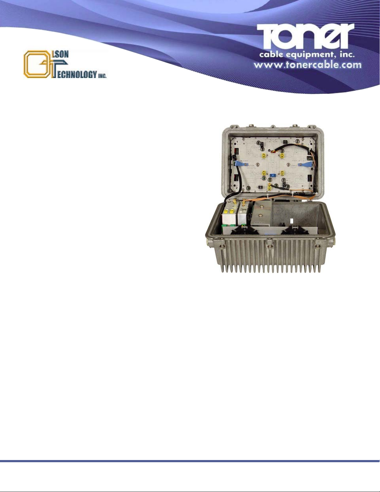
MetroNode 4-Output Compact, Modular, Scaleable Fiber Deep
FTTC Optical Node
969 Horsham Road lHorsham, Pennsylvania 19044 USA l Phone: 215-675-2053 Fax: 215-675-7543 linfo@tonercable.com
The OLSON TECHNOLOGY, INC. MetroNode Model OTMN-II
is a high performance, four output CATV optical node, offering
the capability of greater than +50dBmV output levels. This
node benefits the system operator by extending overall path
length, maximizing equipment usage and reducing the number
of network elements. Full RF output can be maintained with an
optical input as low as -4dBm. With system performance to
870MHz (or optional 1GHz), the MetroNode OTMN-II provides
the ideal platform for support of the evolving technologies and
services in today’s advanced HFC and PON networks.
MetroNode OTMN-II offers protection configurations which are
ideal for critical analog and digital transmission, telephony and
data services. Utilizing extensive modular design with easy infield replacement, the MetroNode OTMN-II can meet any
advanced broadband network requirement.
Features
• Flagship Model of the OT “Metro Node” family.
Field-Proven, 1000’s deployed worldwide
• High Performance, High Output, Economical, Low
Power Dissipation, Two-Way Capable
• Advanced GaAs device technology provides
Excellent RF Performance to 870MHz or optional
1GHz
• Quad RF Amplifier Module provides Four (4)
+50dBmV high level RF Output Ports
• Interstage Slope and RF Input/Output controlled via
internal Plug-in EQs and Plug-in attenuator Pads
• Choice of frequency Diplexer splits: 42/54 MHz -or65/85 MHz for NTSC, PAL & CENELEC use
• +50dBmV High RF Output Levels maintained over
Wide Optical Input Range: +3dBm to -4dBm
• Multiple Redundancy & Segmentation
Configurations via dual Receiver &/or dual
Transmitter Options
• Choice of FP, DFB & CWDM Return Lasers; High
Performance Return Path: >15dB over 41dB NPR
• Power Factor Corrected Switching Power Supply
accepts 40-90VAC; Overvoltage Protection to
140VAC
• Optional High Sensitivity Receiver (-8dBm to 3dBm)
• Optional Powering via 5th Dedicated AC Input Port;
No Power Inserter Required at the node
• Optional use of 5th Power Port for Return Path
Output/Input
• Optional NMS-Standard Status Monitoring &
Control module
• Integrated User-Friendly Fiber Management Tray to
accommodate optical fiber and splices
Page 2

Specifications Subject To Change Without Notice Rev 05-11 ©Toner Cable Equipment, Inc.
969 Horsham Road lHorsham, Pennsylvania 19044 USA l Phone: 215-675-2053 Fax: 215-675-7543 linfo@tonercable.com
Specifications
OTMN-II
MetroNode 4-Output Compact, Modular, Scaleable Fiber Deep
FTTC Optical Node
Optical Input Range (Standard) . . . . . . . . . . . . . . . . . . . . . . . .-4dBm to +3dBm
Optical Input Range (Optional High Sensitivity) . . . . . . . . . . .-8dBm to -3dBm
Forward Frequency Range . . . . . . . . . . . . . . . . . . . . . . . . . . .54MHz to 870MHz or 85MHz to 870MHz (optional 1GHz top end)
Reverse Frequency Range . . . . . . . . . . . . . . . . . . . . . . . . . . .5MHz to 42MHz or 5MHz to 65MHz
Forward Frequency Response . . . . . . . . . . . . . . . . . . . . . . . .<±0.75dB to 870MHz, ±1.0dB from 54MHz to 1GHz
Reverse Frequency Response . . . . . . . . . . . . . . . . . . . . . . . .<±0.75dB 5MHz to 42MHz or 5MHz to 65MHz
Output Level (Forward) . . . . . . . . . . . . . . . . . . . . . . . . . . . . . .+50dBmV @ 550MHz (Each of four outputs)
With -1dBm optical input, 10dB slope to 870MHz, and Transmitter
OMI @ 3.2%. (1GHz option is 12dB slope and +48dBmV output)
Distortion . . . . . . . . . . . . . . . . . . . . . . . . . . . . . . . . . . . . . . . . .>62dB CSO/CTB @ above output and +3dBm optical input.
Carrier loading (77 channels) to 550MHz. Simulated data loading
@ -6dB from 550MHz to 870MHz (or optional 1GHz)
Carrier to Noise . . . . . . . . . . . . . . . . . . . . . . . . . . . . . . . . . . . .>53dB @ -1dBm optical or greater
Carrier loading (77 channels) to 550MHz
In/Out Return Loss . . . . . . . . . . . . . . . . . . . . . . . . . . . . . . . . .>16dB - All ports 1 through 4 (as applicable) from 54-870MHz
>14dB - All ports 1 through 4 (as applicable) from 54MHz-1GHz
Port 5 (power port) >15dB to 65MHz with optional return port configuration
Return Laser Output Power(s) . . . . . . . . . . . . . . . . . . . . . . . . . 1.5, 2.0, 2.5 and 3.0mW ±0.5mW
Return Path NP . . . . . . . . . . . . . . . . . . . . . . . . . . . . . . . . . . . .Range over 41dB NPR is >15dB measured with 10dB of fiber
(With DFB Return Laser & OT LP-OR-300 return band receiver)
Return Path NPR . . . . . . . . . . . . . . . . . . . . . . . . . . . . . . . . . . .Range over 41dB NPR is as follows:(With DFB Return Laser) >13dB
measured with 10dB of fiber as above and both bands moving together.
Return Path NPR Threshold . . . . . . . . . . . . . . . . . . . . . . . . . .< -57dBmV/Hz
Operating Temperature Range . . . . . . . . . . . . . . . . . . . . . . . .-40°C to +65°C
Gain Variation vs. Temperature . . . . . . . . . . . . . . . . . . . . . . . .<±1dB typical
<±1.5dB Max
<±1.8dB REVERSE
AC Power Requirements . . . . . . . . . . . . . . . . . . . . . . . . . . . . .76.5 Watts @ 60 VAC @ 50-60Hz; (45VAC to 90VAC).
Will withstand overvoltage to 140 VAC
Internal Test Points . . . . . . . . . . . . . . . . . . . . . . . . . . . . . . . . .See unit diagram for functional description and location
Hum Modulation . . . . . . . . . . . . . . . . . . . . . . . . . . . . . . . . . . . .>60dB @ 15 Amps AC current from any one port 7MHz to 25MHz
>65dB @ 15 Amps AC current from any one port 25MHz to 870MHz
Size . . . . . . . . . . . . . . . . . . . . . . . . . . . . . . . . . . . . . . . . . . . . .11-1/2"W x 8-1/4"D x 9"H
N - # Outputs/Diplexer
0: 4-Output; 42/54
MHz
1: 4-Output; 65/85
MHz
XYZ - Return Transmitter(s)
000: No Return Transmitter
X = 0 (Single Transmitter)
1 (Dual Transmitter)
2 (1 TX; Status Monitoring TR)
3 (Dual TX; Split Feeder
Return)
Y = 2 (3mW DFB NTSC; 1310nm)
3 (3mW DFB PAL; 1310nm)
4 (1.5mW FP NTSC; 1310nm)
5 (1.5mW FP PAL; 1310nm)
6 (2.5mW DFB NTSC; 1550nm)
7 (2.5mW DFB PAL; 1550nm)
8 (2mW FP NTSC; 1310nm)
9 (2mW FP PAL; 1310nm)
Z = A (Filter Bypass)
B (10MHz High Pass Filter
AB - Receiver (s)
00: Single RX (std)
01: Dual RX w/ABS
02: Split Band Dual RX
03: High Sensitivity RX
CD - 5th Port Return
00: No 5th Port Return
01: 5th Port Return
EF - Status Monitoring
00: Without Status
01: With Status
/OPT - Other Options
/P: Powdercoating
/GHz: 1 GHz Bandwidth
Other options as
required (contact facto-
1) Plug-In Equalizers
Model #9508xxL (Individual 870 MHz Equalizer; xx = value 00 to 22)
Model #950800K (15 EQ 870 MHz Equalizer Kit; values 08 to 22)
Model #951015L (Individual 1 GHz Equalizer; 15 dB)
2) Plug-In Attenuators (19 Values; Specify 0dB to 18 dB in 1 dB increments.)
Model #9518xxL (Individual Attenuator Pads; xx = value 00 to 18)
Model #951800K (19 Pads Attenuator Kit; values 00 to 18)
*Typical 870 MHz OTMN-II node shipped with 10dB slope & +50dBmV output/port @ - 1 dBm optical
in. 1 GHz nodes ship with 12 dB slope and +48 dBmV output port @ -1dBm optical in.
Optional Pad & EQ accessories needed for different performance values.
OTMN -
OTMN-II Model Number Configuator
 Loading...