

Page 1
OT-1000-HH
1 GHz SuperMod 1550nm Optical Transmitter
969 Horsham Road lHorsham, Pennsylvania 19044 USA l Phone: 215-675-2053 Fax: 215-675-7543 linfo@tonercable.com
The Olson Technology, Inc. LaserLite Model OT-1000-HH 1GHz SuperMod
(Direct Mod) 1550nm Optical Transmitter is a cost effective, high quality,
full-featured 1RU 19" optical transmitter. Designed for optical transport of
forward path analog, return path and digital QAM broadcast signals, the OT1000-HH transmitter is ideal for CATV Hybrid Fiber Coax (HFC) applications
and Fiber-to-the-Premise (FTTP) deployments using Active/Passive Optical
Network (AON/PON) architectures.
The Model OT-1000-HH transmitter utilizes a high-quality, DFB, low-chirp,
optically isolated DWDM laser that uses advanced predistortion, SBS and
pre-chirping technology to provide excellent signal quality. Often referred to
as a Direct Mod 1550 nm transmitter, the OT-1000-HH SuperMod transmitter approaches External Modulator performance levels at distances from 0
to 20km at a substantially lower cost. The transmitter operates in the ITUgrid wavelength with adjustable wavelength to ±100GHz when used with the
Network Controller. The Network Controller can control a wide range of
transmitter parameters.
The OT-1000-HH provides exterior RF and optical connections and test
points. These are the perfect companion to Olson Technology’s LaserLite
OTEA-CO, OTEB-CO and OTEA-CM series EDFA’s and the MetroNode
Model OTMN-x and PremiseNode Model OTPN-x product families, but is
also designed to operate seamlessly with optical receivers and/or nodes
from most leading manufacturers.
Electrical to optical conversion of multichannel CATV
signals.
• Supports AM-VSB, FM, 8-VSB and
QAM CATV signals.
• Low noise SuperMod (DirectMod)
1550nm DFB Transmitter with predistortion technology; DWDM variants available.
• Very high-quality transmission from
0-20km. Usable to 35km.
• Available RF bandwidth of 51,000MHz for CATV digital multichannel transport.
• Downstream or upstream transmission in HFC networks.
• Optical output of +8dBm
• Advanced SBS suppression and
pre-chirping technology.
• Dual RF inputs: low and high level
inputs or optional narrowcast input
with high isolation.
• Preset or optional adjustment of
slope, gain, output power, OMI, prechirping, etc.
• Automatic load control (ALC) for
constant OMI
totrms
.
• SC/APC optical connector; RS485
control interface.
• 1RU 19” EIA rack mount chassis.
Page 2

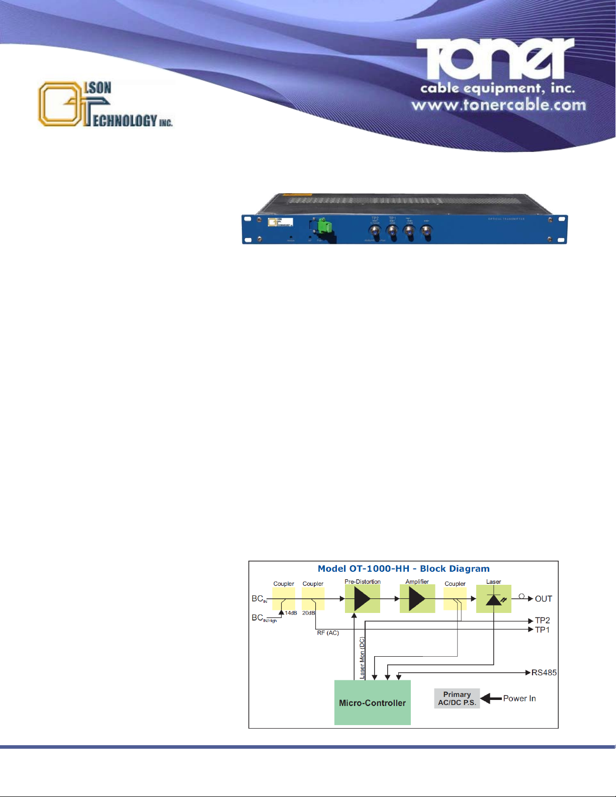
Test Points
Test Point TP1 20db Attenuation of RF Input
Test Point TP2 Dual Readings - +20dBmV+2ΔP
OPT
±2.0dB at OMI=5% (AC) / 0.1V/mW ±0.02V/mW (DC)
Transmission Performance Data
Channel Allocation Plan “C” “B” “N”
Number of Carriers/Plan Cenelec (42) PAL B/G (36) NTSC (77)
Optical Modulation Index 4.1% 4.4% 3.0%
Noise Bandwidth 5MHz 5MHz 4MHz
CNR ≥51dB ≥52dB ≥51dB
CSO
1,2
≥60dBc
3
≥60dBc ≥60dBc
CTB
1,2
≥62dBc ≥64dBc ≥63dBc
TEST CONDITIONS:
1) 20km non-dispersion shifted fiber, optical attenuator and optical receiver with P
OPTIN
=0dBm, Ieq=7.0pA/√Hz and η=0.95A/W (at 1550nm) used.
2) Non-dispersion shifted fiber, 0-20km, optical attenuator and optical receiver with P
OPTIN
=0dBm, Ieq=7.0pA/√Hz and η=0.95A/W used and fiber
length (chirp) compensation adjustment set to optimum.
3) Only for measured frequencies up to 600MHz. Otherwise the CSO value is 6dB lower.
Specifications Subject To Change Without Notice Rev 06-11 ©Toner Cable Equipment, Inc.
969 Horsham Road lHorsham, Pennsylvania 19044 USA l Phone: 215-675-2053 Fax: 215-675-7543 linfo@tonercable.com
Min Typ Max Units
Optical Output Pwr.
1
+7 +8 +9 dBm
Optical Output Pwr. Adj.
3
-3 0 dB
Output Pwr. Tolerance -1.5 +1.5 dB
Optical Wavelength Tuning
3
-100 +100 Ghz
Chirp Compensation Distance
4,5
0 20 km
SBS Suppression +15 dBm
Optical Return Loss 45 dB
Optical Connector SC/APC
Wavelength
1
DWDM
Specifications
OT-1000-HH
1 GHz SuperMod 1550nm Optical Transmitter
Min Typ Max Units
Power Supply Voltage +100 +240 V
AC
Power Supply Voltage +36 +60 V
DC
Power Supply Frequency 50 60 Hz
Power Consumption 17 W
Environmental Cond. Class 3.1 acc.
ETS 300 019-1-3
(temp. controlled)
Safety Cond. EN 50 083-1
EN 60 950
Laser Class 1M acc,
IEC 60 825-1
EMC Cond. EN 50 83-2
Min Typ Max Units
Frequency Range 5 1,000 MHz
Input Impedance 75 Ohms
Input Level (OMI 5%, BC
IN
) 13 dbmV
Input Level (OMI 5%, BC
IN/High
) 27 dbmV
Gain Adjustment
3
-17 7 dB
Slope Adjustment
3
-3 +16 dB
RF Return Loss (@47MHz)
2
20 dB
RF Return Loss (@5-65MHz) 18 dB
NOTES:
1) Output power tolerance is ±1dB at transmitter pigtail.
2) RF return loss is 20dB at 47MHz, 1.5dB/oct, min. 15dB.
3) These adjustments are made through the NEC-E Controller
4) The chirp compensation distance can be set through the
optional NECE Controller or the unit may be ordered with a
preset distance.
5) The chirp compensation can be set as high as 35km with
reduced performance. Contact factory for details.
Ordering Information
Model
OT-1000-HHcxx-yy-z LaserLite Tx, 5-1000MHz,
+8dBm Output, DWDM, 75 Ω,
SC/APC
Optical Characteristics (with SM 9/125μm Fiber)
Electrical and Environmental Characteristics
RF Characteristics
NOTES:
1) “c” indicates the “Channel Allocation Plan.” (See above). “C”, “B” or “N”
2) “xx” indicates the ITU channel. Channels 22-46. Order “34” for std 1550nm.
3) “yy” is the factory set dispersion compensation distance in km. For example,
“15” indicates that the unit is optimized for 15km distance.
4) “z” indicates the power supply. “A” for AC power, “D” for DC power.
Min Typ Max Units
Weight 4.4 lbs
2kg
Dimensions(WxHxD) 19 x 9.5 x 1.75 in
483 x 240 x 45 mm
Physical Characteristics
 Loading...