

Page 1
Telephone: Nationwide: Fax: E-mail: Internet:
5/00
Linear Fiber Optic LightLinks™
215-675-2053 800-523-5947 215-675-7543 info@tonercable.com http://www.tonercable.com
969 Horsham Road
Horsham, Pennsylvania 19044 USA
Linear Fiber Optic LightLinks™
Providing direct broadcast satellite service to customers in medium and large-size multiple-dwelling
unit (MDU) properties without compromising the
satellite link budget can be extremely difficult using
coaxial cables. The insertion loss of type RG-6 coaxial cable is approximately 9 dB per 100 foot length at
1450 MHz and 11 dB at 2050 MHz, resulting in
severe distance limitations. This effectively precludes using a single cable to carry both satellite
polarizations simultaneously, making it difficult to
connect more than one satellite receiver (IRD) in an
individual apartment or condominium unit.
Fortunately, linear fiber optics can be employed as
a cost-effective way of providing DBS distribution
with negligible signal losses at distances of thousands of feet.
In conventional, all-coaxial distribution systems, the
high coaxial insertion loss and the loss in passive
components such as splitters and directional taps
can be offset using in-line amplifiers, but only up to a
point. Cascading several of these devices along the
same path can degrade the signal quality and
reduce the rain fade margin by introducing excessive noise and intermodulation distortion. The size of
the distribution network is therefore limited, and the
LightLinks™ Family of DBS distribution products
system must be carefully designed and implemented
to ensure that signal losses are accounted for along
every single path.
Multiswitches can be used to combine both polarizations onto a single drop cable, because the IRD typically selects either one or the other by setting the dc
voltage on the center conductor of the drop cable.
But multiswitches are expensive, and require that
each IRD uses one multiswitch output and its own
drop cable, even if other IRDs are in the same unit.
Using Linear Fiber Optic Lightlinks™ for Direct Broadcast
Satellite Reception in Multiple Dwelling Units
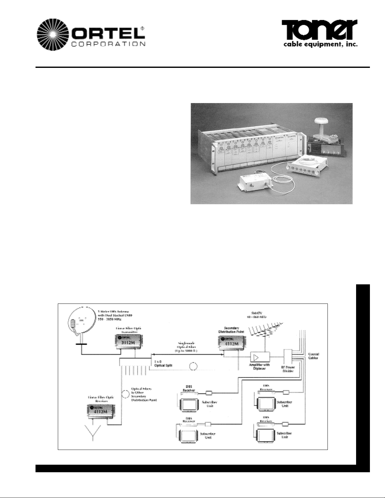
Figure 1: Linear Fiber Optic LightLinks™ MDU Distribution System
Page 2
”Toner Cable Equipment, Inc. Specifications Subject To Change Without Notice.
Telephone: Nationwide: Fax: E-mail: Internet:
Linear Fiber Optic LightLinks™
215-675-2053 800-523-5947 215-675-7543 info@tonercable.com http://www.tonercable.com
Using Linear Fiber Optics for Direct Broadcast Satellite Reception
in Multiple Dwelling Units
The MDU distribution system shown in Figure 1 can be
used to provide DBS service to well over 100 units
without using coaxial cable longer than 150 feet, and
with negligible signal quality degradation. Asingle Ortel
model 3112M transmitter sends both polarizations
(which have been combined at the antenna onto a single cable) to eight model 4112M receivers at secondary
distribution points throughout the property (e.g., different floors of a high-rise building). The fiber optic cables
may be thousands of feet in length and still add less
than 1 dB of RF insertion loss, even at 2050 MHz.
From there the usual network of splitters and/or taps is
used to connect to approximately twenty individual
units per secondary distribution point. Off-air channels
can either be diplexed in at the secondary distribution
point, or added to the fiberoptic transport system.
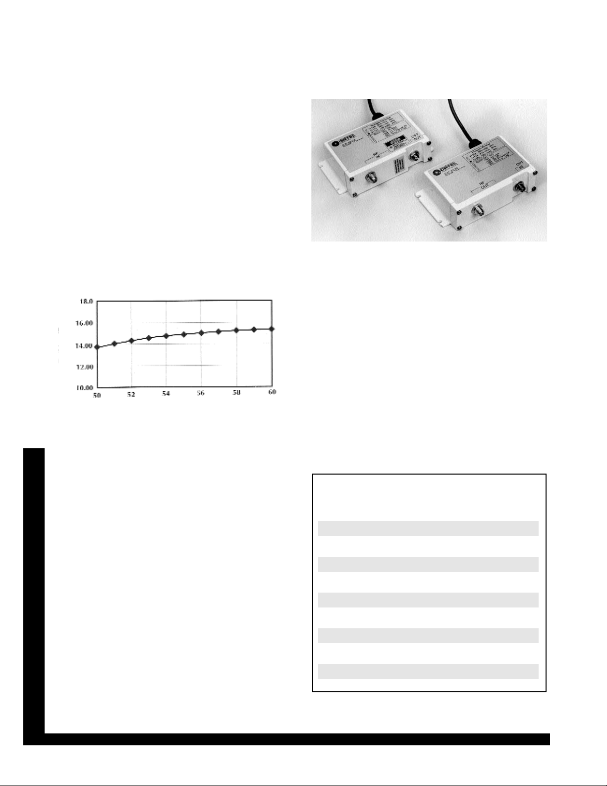
Figure 2 shows the overall system performance as a
function of the gain of the antenna Low Noise Block
Downconvertor/Feed (LNBF). The gain typically varies
from one LNBF to the next, as well as over temperature since the LNBF must be outdoors.
The baseband energy per bit per noise density (Eb/N0)
varies little as a function of LNBF gain, eliminating the
need for either a manual gain adjustment or automatic
gain control (AGC). The installer merely connects the
LNBF output directly to the 3112M input connector
using an RG-6 cable. Threshold Eb/N0 is 5 to 6 dB, so
the 60 cm antenna yields nearly 10 dB rain margin.
Two-tone IM distortion products are less than -30 dBc
over the entire LNBF gain range.
Another problem with the all-coaxial approach is that
dc power must be provided to amplifiers and multiswitches as well as to the LNBF. The coaxial cables
often must carry dc current through their center conductors, further complicating both design and installation, and a single device failure can result in loss of
service to many customers. Using fiber partitions the
system into several small electrical networks, and
enhances overall reliability by considerably reducing
the number of active elements.
Ortel 3112M & 4112M LightLinks™ Transmitter & Receiver
A single wall-plug transformer power supply can be used
to power both the 3112M optical transmitter and the dual
stacked LNBF; the LNBF current is fed from the 3112M
via the center conductor of the antenna cable.
L-band signal distribution using Ortel’s inexpensive linear fiber optic transmitters and receivers dramatically
reduces engineering and installation costs in medium
and large MDUs, and completely eliminates multiswitches. There is no penalty in terms of performance, so all
of the rain fade margin that was designed into the satellite link budget is preserved. Afurther advantage is that
all of the satellite transponders are carried on a single
line, enabling multi-room distribution from a single drop.
ORDERING INFORMATION
Model Description
3112M Transmitter, 950-2050 MHz, Flanged Mount
4112M Receiver, 950-2050 MHz, Flanged Mount
10347M Transmitter, 950-2050 MHz, Plug-In
10447M Receiver, 950-2050 MHz, Plug-In
10357A Transmitter, IF, 10-200 MHz, Plug-In
10457A Receiver, IF, 10-200 MHz, Plug-In
10990A Rack Chassis for Plug-Ins, 19" x 3RU
10901A Main Power Supply for Rack Chassis
10901B Standby Power Supply for Rack Chassis
Figure 2: Eb/N0vs LNBF Gain
LNBF Gain, dB
E
b
/N
0
, dB
 Loading...