

Page 1
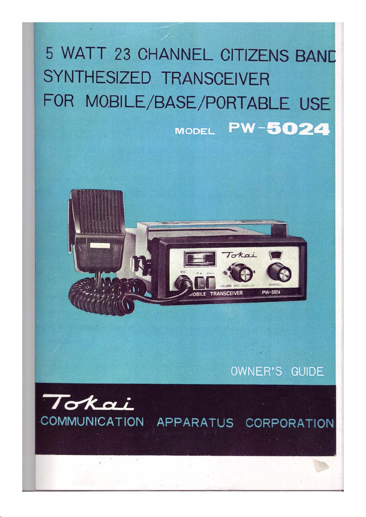
5
WATT
23
CHANNEL
CITIZENS
BAN
SYNTHESIZED
FOR
MOBILE/BASE/PORT ABLE
TRANSCEIVER
USE
Page 2
FUNCTION
OF
CONTROLS
Volume control
The volume control varies the sound out put of the lound speaker.
To turn set
To turn set
Channel Selector :
The center control
frequencies simultaneous!
Make sure the switch
Squelch Control
The squelch control is designed to reduce
and
On-Off
on
and
to increase volume, turn
off
or to decrease
on
:
switch :
the front
volume,
panel
turn
selects both receiver
y.
is
set to desired channel.
on-off
on-off
exc~~$ive
switch clockwise.
switch counterclockwise.
nqise such as highline in-
and
transmitter
terference, ignition noise, etc
ase the
When
blanked out.
volume untill noise or a signa.1
only noise is present, turn the squelch control clockwise until t1e noise
..
Turn the control fully counterc lockwi
is
heard.
se
and
incre-
is
Page 3
:··
'' GENERAL OPERATING
.:-
' . .
.-
INSTRUCTIONS
' . .
..
1. Check to see
system, microphone.
Be
sure that the transceiver is properly grounded
a .metal surface.
2.
Select the channel
switch.
3.
To
transmit, press the push-to-talk switch
The illumination lamp
transmitting condition.
Release this switch to receive.
The easy-to-read combination
put power.
if
proper connections have
you
at
desire to operate
the upper
"S"
left
/RF
meter also indicates relative
been
made
on
power cables, antenna
if
not mounted directly
on
by rotating the channel selector
and
hold
it
down.
side of the front visually indicates
RF
on
out-
4.
Adjust receiver noise level with the "Squelch Control".
:
··
MO~ILE
Mounting - Select a suitable place under the dashboard
the ones
the screws
install near heater outlets.
Antenna
- It is most suitable to install a CB Mobile Whip Antenna,
i
02
also
at
IN,STALLATIO~
on
the Mounting Bracket. Securely fasten the Bracket with
and
nuts and then install Unit with knob screws. Don't
inches long
be
used. Connect the Antenna coaxial plug to the Socket located
the right side of the unit.
and
50
ohm
impedance. Loading Coil Antenna can
.·
and
drill holes matching
Yz
wave,
Page 4

Fig. I
INSTRUMENT
of
DASHBOARD
PANEL
~-
---
~
---
~----
NUT
-SPRI
WASHER
SCREW
~eoLT
NG
WASHER
-=~=:===:
fr P.
rr======
®
=:==:==:=
r.
~.r:::
E
,....
:::--:
==:=;i~~~~~~~
==;b=
s
::-:
OA
:----T.':--~';;;
~~~
~==~;;;;;;;;;;;;;;;;;;;;;;;;;;;;;;;;;;;;;;;;;;~-
:
;:---~"<;;-:;;:;:-~:=:===:i
::sc==:::=
-EXTERNAL
~+-11..
ll--
"50l--tt-~-
a
Fig. 2
power cord - This
Red
and
not
only
unit can
Cord is to
be
be
connected to the
the Black Cord to the car body
glow
when
the power switch
~
used
on a 12
is
volts negative ground car. The
9.
"ON", check the Fuse.-2 A fuse
ANTENNA
A.
SELE
- POW
~
~
EB
side of the car battery
SOCKET
SPEAKER
CTI
ER
JACK
SPEAKER
VE
CALL
SL.PPL Y
POSITIVE
NEGATIVE(BLACK
JACK
SOCKET
SOCKET
(
RED
)
)
If the indicator lamp does
12
VDC
should
be
used for replacement.
External speaker - A speaker jack is provided for use with
nal
speaker. Use a
rted, the
buil
- in speaker
plug
for th
in
the
is
jack, when the
set
is automatically disconn-
an
8
ohm
plug
exter -
is inse -
Page 5

ected and speaker which
you
have connected
in
the
plug
ope
-
Public address
BASE
Antenna -
rates.
ther terminal
system -
Note : The
is
connected to the car
To
use your new PW - 5024 as a public address sys-
tem, connect any standard 8
Keep pressing down the
ugh
P.A.
system . .
INSTALLATION
When
zen's Band
provide greater coverage,
rectional .
the
PW-5
beam,
It
024
dipole, ground plane or vertical antenna will
is
ideal in base station to mobile operation.
external speaker will not
body
or ground
ohm
PA
speaker to PA jack.
P.A.
switch during you speak thro-
is used as a base station,
and
since
it
is essentially non-di -
work
any
if
Citi -
e1
-
Fig
. 3
From base staion to base station or point-to-point opeation a
ir
ectional
d
beam
will give greater distance even under adve-
rse conditions.
Generally, a maximum of 26feet of coax lead-in cable sho utd
be
used
due
to line-losses, however, a desirable antenna
location
may
justify the loss in extra! lead
MCOCL
PW.
5024
in
length.
•
MCOCL
A· 142
Page 6

PORTABLE
Fi
g .4
I .
Open
back
INSTALLAT~N
cav.ar
and
..i
nsert _ 8 flashlight ".
G"
cells, or I 0 pcs. of I .
25
V . nickel·cadmium battery carefully observing polarities. Check to see that
batteries are
2.
Pl
ug
power supply line cord to the socket of PW-5024 and attach to Tokai
PW-5024
3 . Set T okai A -
4.
Turn the "
5 . Battery
rate
when
the battery requires replace
firmly seated.
transceiver correctly.
173
coil-loaded antenna.
ON-OFF & VOLUME
Checker Meter: pushing the battery button,
the neelde
is
in blue zone.
CAUTION: U
" switch to "
ing
or chaging.
se eight"
dummy batt eries or ten
ON
When
C " carbon I .5 volt cell s with
the
" position.
it
is
good
need
le is
I .25 volt cells
for to ope-
in
red
zone,
wi
-
th dummy batteries removed.
Page 7

c
"O
Q)
~
c
-
~
a..
-.::t"
N
0
LO
I
~
Q.
Page 8

 Loading...