

Page 1
INSTRUCTION MANUAL
EMERGENCY POWER SUPPLY
POWER SUPPLY FRAME
POWER SUPPLY UNIT
VX-2000DS ER
VX-2000DS UK
VX-2000DS SA
VX-2000PF
VX-200PS ER
VX-200PS UK
VX-200PS SA
Thank you for purchasing TOA's Emergency Power Supply, Power Supply Frame, and Power Supply
Unit.
Please carefully follow the instructions in this manual to ensure long, trouble-free use of your equipment.
1134
TOA Electronics Europe GmbH
Suederstrasse 282, 20537 Hamburg, Germany
1134-CPR-083
14
DoP 1134-CPD-083
EN 54-4: 1997/A1: 2002 + A2: 2006
Power supply equipment for fire detection and fire alarm systems for buildings
VX-2000DS ER/UK, VX-200PS ER/UK
(Does not apply to VX-2000DS SA and VX-200PS SA)
Page 2

2
TABLE OF CONTENTS
1. SAFETY PRECAUTIONS ................................................................................. 3
2. NOMENCLATURE AND FUNCTIONS
2.1. VX-2000DS Emergency Power Supply .............................................................. 5
2.2. VX-200PS Power Supply Unit ............................................................................ 7
2.3. VX-2000PF Power Supply Frame ...................................................................... 8
3. INSTALLATION
3.1. Assembling the VX-2000PF Power Supply Frame ............................................ 9
3.2. Installing the VX-200PS Power Supply Unit in the VX-2000PF ....................... 10
3.3. Battery Installation ............................................................................................ 11
3.4. Affixing Declaration of Compliance (EN 54-4 Standard) .................................. 15
4. CONNECTIONS WHEN USING WITH THE VX-2000 SYSTEM
4.1. Connections between VX-2000DS and VX-200PS .......................................... 16
4.2. Connecting the VX-2000DS to VX-2000 System ............................................. 17
5. CONNECTIONS WHEN USING WITH THE SX-2000 SYSTEM
5.1. Connections between VX-2000DS and VX-200PS .......................................... 18
5.2. Connecting the VX-2000DS to SX-2000 System ............................................. 19
5.3. DS Link Terminal Connections ......................................................................... 21
6. CONNECTIONS WHEN USING WITH THE VM-3000 SYSTEM ....... 22
7. CABLE USAGE TABLE ................................................................................. 26
8. USING THE VX-2000DS EXCLUSIVELY AS A BACKUP
POWER SUPPLY
.............................................................................................. 27
9. SWITCHING OFF SYSTEM POWER (DC) ............................................... 28
10. BLOCK DIAGRAM ........................................................................................... 29
11. SPECIFICATIONS
11.1. VX-2000DS Emergency Power Supply .......................................................... 30
11.2. VX-200PS Power Supply Unit ........................................................................ 31
11.3. VX-2000PF Power Supply Frame ................................................................. 31
Page 3

3
1. SAFETY PRECAUTIONS
• Before installation or use, be sure to carefully read all the instructions in this section for correct and safe
operation.
• Be sure to follow all the precautionary instructions in this section, which contain important warnings and/or
cautions regarding safety.
• After reading, keep this manual handy for future reference.
When Installing the Unit
• Do not expose the unit to rain or an environment where it may be splashed by water or other liquids, as
doing so may result in fire or electric shock.
• Use the unit only with the voltage specified on the unit. Using a voltage higher than that which is specified
may result in fire or electric shock.
• (Applicable to VX-2000DS and VX-200PS only)
Do not cut, kink, otherwise damage nor modify the power supply cord. In addition, avoid using the power
cord in close proximity to heaters, and never place heavy objects -- including the unit itself -- on the power
cord, as doing so may result in fire or electric shock.
• Since the unit is designed for in-door use, do not install it outdoors. If installed outdoors, the aging of parts
causes the unit to fall off, resulting in personal injury. Also, when it gets wet with rain, there is a danger of
electric shock.
When the Unit is in Use
• Should the following irregularity be found during use, immediately switch off the main power (or circuit
breaker), and contact your nearest TOA dealer. Make no further attempt to operate the unit in this condition
as this may cause fire or electric shock.
· If you detect smoke or a strange smell coming from the unit.
· If water or any metallic object gets into the unit
· If the unit falls, or the unit case breaks
· (Applicable to VX-2000DS and VX-200PS only)
If the power supply cord is damaged (exposure of the core, disconnection, etc.)
· If it is malfunctioning (no tone sounds.)
• To prevent a fire or electric shock, never open the unit case nor modify the unit. Refer all servicing to
qualified service personnel.
• Do not place cups, bowls, or other containers of liquid or metallic objects on top of the unit. If they
accidentally spill into the unit, this may cause a fire or electric shock.
• (Applicable to VX-2000DS and VX-200PS only)
Do not insert nor drop metallic objects or flammable materials in the ventilation slots of the unit's cover as
this may result in fire or electric shock.
• (Applicable to VX-2000DS and VX-200PS only)
Do not touch a power supply plug during thunder and lightning, as this may result in electric shock.
• (Applicable to VX-200PS only)
When replacing the fuse, be sure to use the supplied one (3.15 A). Using any other fuse than supplied may
cause fire or electric shock.
Indicates a potentially hazardous situation which, if mishandled, could
result in death or serious personal injury.
WARNING
Page 4

4
When Installing the Unit
• (Applicable to VX-2000DS and VX-200PS only)
Never plug in nor remove the power supply plug with wet hands, as doing so may cause electric shock.
• (Applicable to VX-2000DS and VX-200PS only)
When unplugging the power supply cord, be sure to grasp the power supply plug; never pull on the cord
itself. Operating the unit with a damaged power supply cord may cause a fire or electric shock.
• (Applicable to VX-2000DS and VX-200PS only)
Do not block the ventilation slots in the unit's cover. Doing so may cause heat to build up inside the unit and
result in fire.
•
Avoid installing the unit in humid or dusty locations, in locations exposed to the direct sunlight, near the heaters,
or in locations generating sooty smoke or steam as doing otherwise may result in fire or electric shock.
• System units (except remote microphones) are designed exclusively to be mounted in an equipment rack.
Be sure to observe the following instructions when rack-mounting the unit. Failure to do so may cause a fire
or personal injury.
· Install the equipment rack on a stable, hard floor. Fix it with anchor bolts or take other arrangements to
prevent it from falling down.
· When connecting the power cord of the DC power supply panel for the units to an AC outlet, ensure that
the total load current never exceeds the AC outlet's allowable current capacity.
· The supplied rack-mounting screws can be used for the TOA equipment rack only. Do not use them for
other racks.
• (Applicable to VX-2000DS only)
Note correct polarity (positive and negative orientation) when connecting the power supply cord. Reversed
polarity connections will cause damage to the system.
When the Unit is in Use
• Use the specified power supply unit for the system. Note that the use of other power supply unit may cause
a fire.
• (Applicable to VX-2000DS only)
Make sure to observe the following handling precautions so that a fire or personal injury does not result from
leakage or explosion of the battery.
· Do not short, disassemble, heat nor put the battery into a fire.
· Avoid using both new and old batteries together.
· Never charge batteries of the type which are not rechargeable.
· Do not solder a battery directly.
· Be sure to use the specified type of batteries.
· Note correct polarity (positive and negative orientation) when connecting a battery to the unit.
· Avoid locations exposed to the direct sunlight, high temperature and high humidity when storing batteries.
• (Applicable to VX-200PS only)
Contact your TOA dealer as to the cleaning. If dust is allowed to accumulate in the unit over a long period of
time, a fire or damage to the unit may result.
Indicates a potentially hazardous situation which, if mishandled, could
result in moderate or minor personal injury, and/or property damage.
CAUTION
Page 5
5
2. NOMENCLATURE AND FUNCTIONS
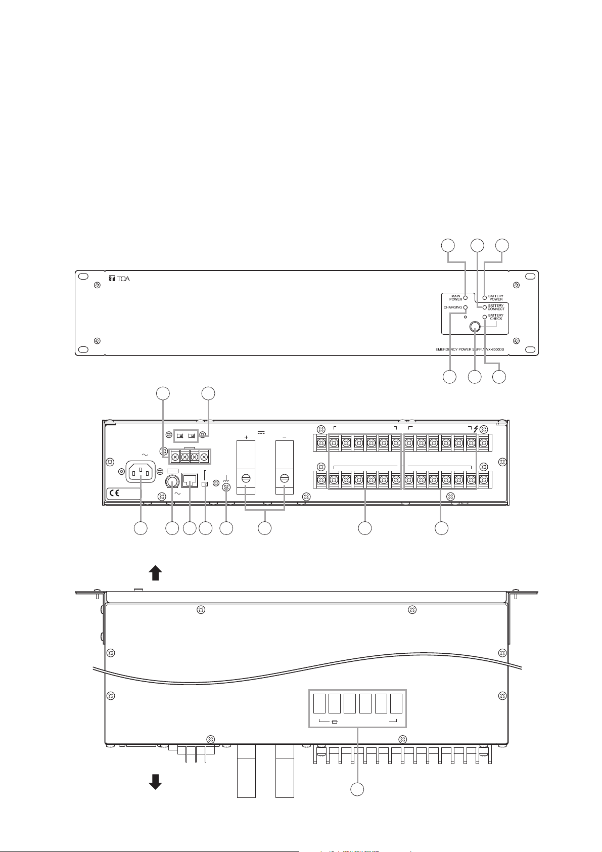
2.1. VX-2000DS Emergency Power Supply
• Up to 3 (6 ch) VX-200PS Power Supply units can be connected per VX-2000DS to supply backup DC power
to individual components.
• Automatically switches to the backup power supply when the DC power supply from the VX-200PS is
interrupted.
• Detects charging circuitry or battery failures, and transmits failure signals to the DS LINK of the TOA Voice
Evacuation Systems (VX-2000, SX-2000, and VM-3000).
• Keeps a 2 x 12 V sealed lead-acid battery charged while maintaining temperature compensation for the
charging voltage.
• Automatically disconnects the battery if its voltage reaches a discharge final level.
1
[Front]
2 3
[Rear]
[Top]
7 8
DC POWER OUT (+) MAX 25A (DC 20V-40V)
1134
50/60Hz 240W
EN 54-4
1134-CPD-083
230V
DETECT(VX-200PS)
PS3 PS2
THERMISTOR
FUSE
T3.15A L
250V
OFFONON OFF
DS – SF
LINK SETTING
DCAC
BATTERY POWER IN
24V MAX150A
( ) ( )
9 10 11 12 13 14 15 16
Note: This figure represents the VX-2000DS ER.
Front side
PS IN (+) MAX 25A (DC20V-40V)
615432615432
( )
5
4
6
PS IN
1,2:PS1
3,4:PS2
5,6:PS3
Rear side
654321
FUSE 40A (DC POWER OUT)
17
Page 6

6
1. Power indicator [MAIN POWER]
Lights green when both DC power from the VX200PS and AC power are supplied.
2. Battery connect indicator
[BATTERY CONNECT]
Lights green when the battery is connected.
3. Battery indicator [BATTERY POWER]
Indicates the state of battery usage. Lights red
when the DC power supply is interrupted and
switched over to the backup power supply.
4. Charging indicator [CHARGING]
Indicates battery charging status. Flashes green
while charging, and continuously lights green
after charging completion.
5. Battery check button
Used to check internal resistance state of the
backup battery.
Pressing the button permits measuring of the
internal resistance value. The Battery check
indicator goes off if the measurement exceeds
the specified value.
In automatic mode, the unit performs battery
check every 3 and a half hours.
When the DS-SF LINK is connected to the VX2000 system, SX-2000 system, or VM-3000
system, the resistance measurement is activated
by the equipment, not by the unit itself.
Note
Battery check cannot function for 1 minute after it
has been activated once. In this case, wait a few
minutes, then reactivate it.
6. Battery check indicator [BATTERY CHECK]
In the AC operated system, the internal
resistance value of the battery is measured
automatically or manually to check whether the
battery is faulty. The Battery check indicator
indicates the result.
• Before measurement:
Flashes green at 2-second intervals.
• During measurement:
Flashes green at 1-second intervals.
• Normal: Lights green.
• Abnormal: Remains unlit.
In the battery-operated system, the battery
voltage is constantly monitored and its level is
indicated by the indicator as shown below
without pressing the Battery check button.
• Lights green: 25 V or more
• Flashes green: 20 – 25 V
• OFF: 20 V or less
7. Thermistor connection terminal
[THERMISTOR]
Detects the ambient temperature of the backup
battery, and performs temperature compensation
for the charging voltage. For the installation
instructions, refer to p. 14.
8. PS detect switches
Always connect a power supply to the terminals
1 + 2 of the DC INPUT. When connecting a
power supply to the terminals 3 + 4 of the DC
INPUT, set the PS2 switch to ON. When
connecting a power supply to the terminals 5 + 6
of the DC INPUT, set the PS3 switch to ON.
9. AC inlet
Using the supplied power cord, connect this AC
line receptacle to a power source of 230 V AC
(ER/UK), 220 – 230 V AC (SA), 50/60 Hz.
10. Fuse holder
Requires an AC fuse.
Type: 250 V, T3.15 A L
11. Control connector [DS-SF LINK]
This RJ45 connector connects to DS-SF LINK
connector of the VX-2000 system, SX-2000
system, or VM-3000 system.
12. Setting switch [SETTING]
Select the DC position (factory set) when using
the unit in the VX-2000 system, SX-2000 system,
or VM-3000 system.
Select the AC position when using the unit as a
backup power supply in an AC-operated system.
Refer to p. 27 for the switch setting in the VM2000 series system or other systems.
13. Ground terminal
14. Battery connection terminal
[BATTERY POWER IN]
Connects to the backup battery.
Recommended battery: Panasonic LCX1265PG/APG sealed lead-acid battery
15. DC output terminal [DC POWER OUT]
Supplies the DC power to the DC-operated
devices.
16. DC input terminal [PS IN]
Connects to the DC output terminal of the VX200PS Power Supply unit or VM-3000 series
(Voice Alarm System Amplifier or VM Extension
Amplifier).
Be sure to connect the first VX-200PS unit or
VM-3000 amplifier to the terminals 1 and 2, the
second unit or amplifier to the terminals 3 and 4,
and the third unit or amplifier to the terminals 5
and 6.
17. Fuse
Provided in each DC output.
Capacity: Blade-Type Fuse 40 A
Page 7
7
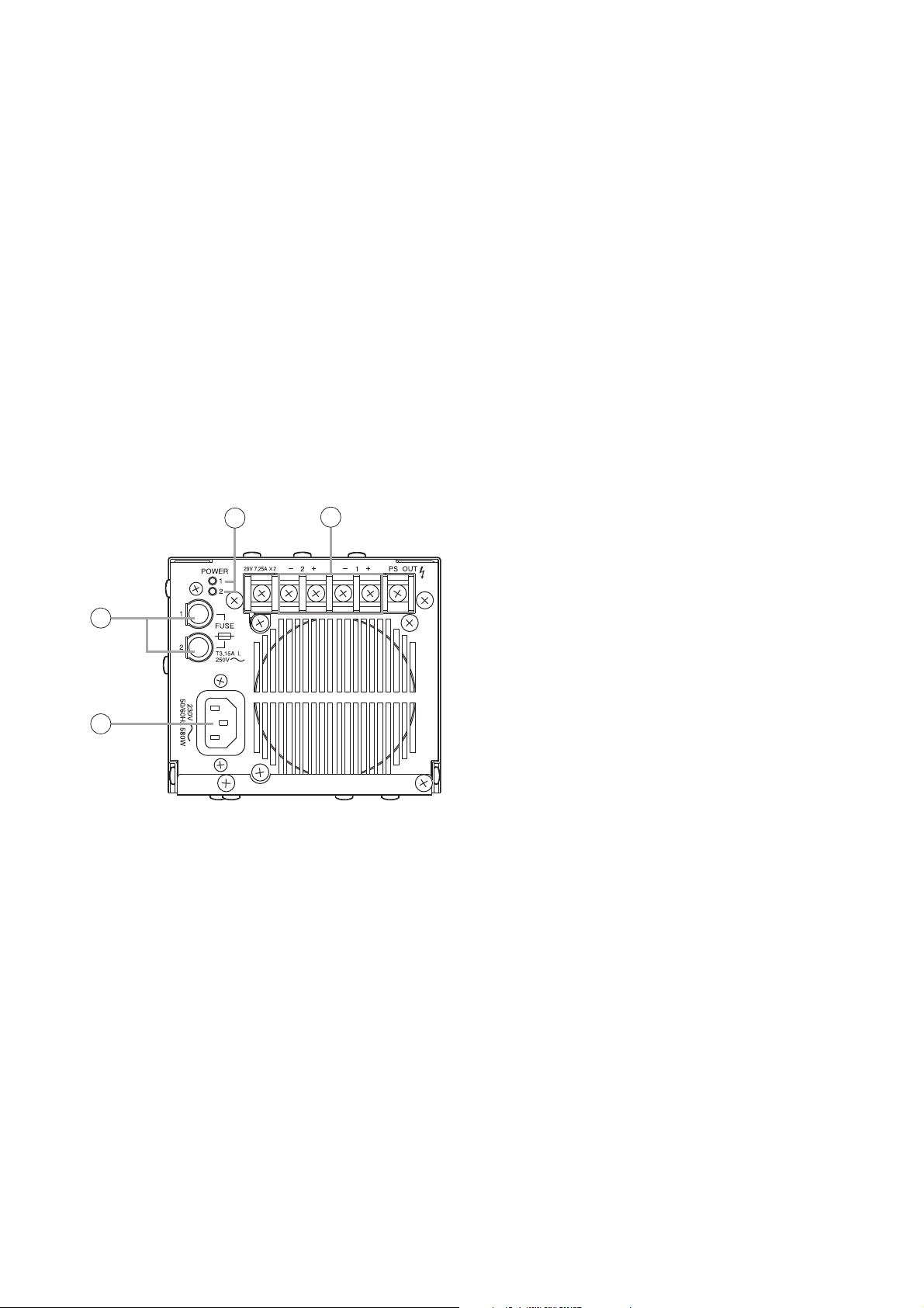
2.2. VX-200PS Power Supply Unit
1. Power indicator [POWER]
These indicators (one for each channel) light
green when DC power is output.
2. DC output terminal 1, 2 [PS OUT]
Connects to the PS IN terminals of the VX2000DS Emergency Power Supply.
3. AC fuse 1, 2
Type: 250 V, T3.15 A L
4. AC inlet
Using the supplied power cord, connect this
AC line receptacle to a power source of 230 V
AC (ER/UK), 220 – 230 V AC (SA), 50/60 Hz.
Note
The VX-200PS Power Supply unit is designed for exclusive use with the VX-2000 system, SX-2000 system,
and VM-3000 system.
Up to 3 VX-200PS Power Supply units can be mounted in the V-2000PF Power Supply Frame. The VX200PS unit has 2 DC output channels, and up to 3 units (6 ch) can be connected to one VX-2000DS
Emergency Power Supply. Use the VX-200PS in the number suited to the required total system power.
[Fault indication]
If any of the Power indicator [MAIN POWER], Battery connect indicator [BATTERY CONNECT], Charging
indicator [CHARGING], or Battery check indicator [BATTERY CHECK] on the front panel remains unlit, the
unit is judged failed. In such cases, remove the cause of the failure, and restore the unit to normal operation.
Note
Even if any of these indicators flashes, this does not indicate malfunction.
[Rear]
1
2
3
4
Page 8
8
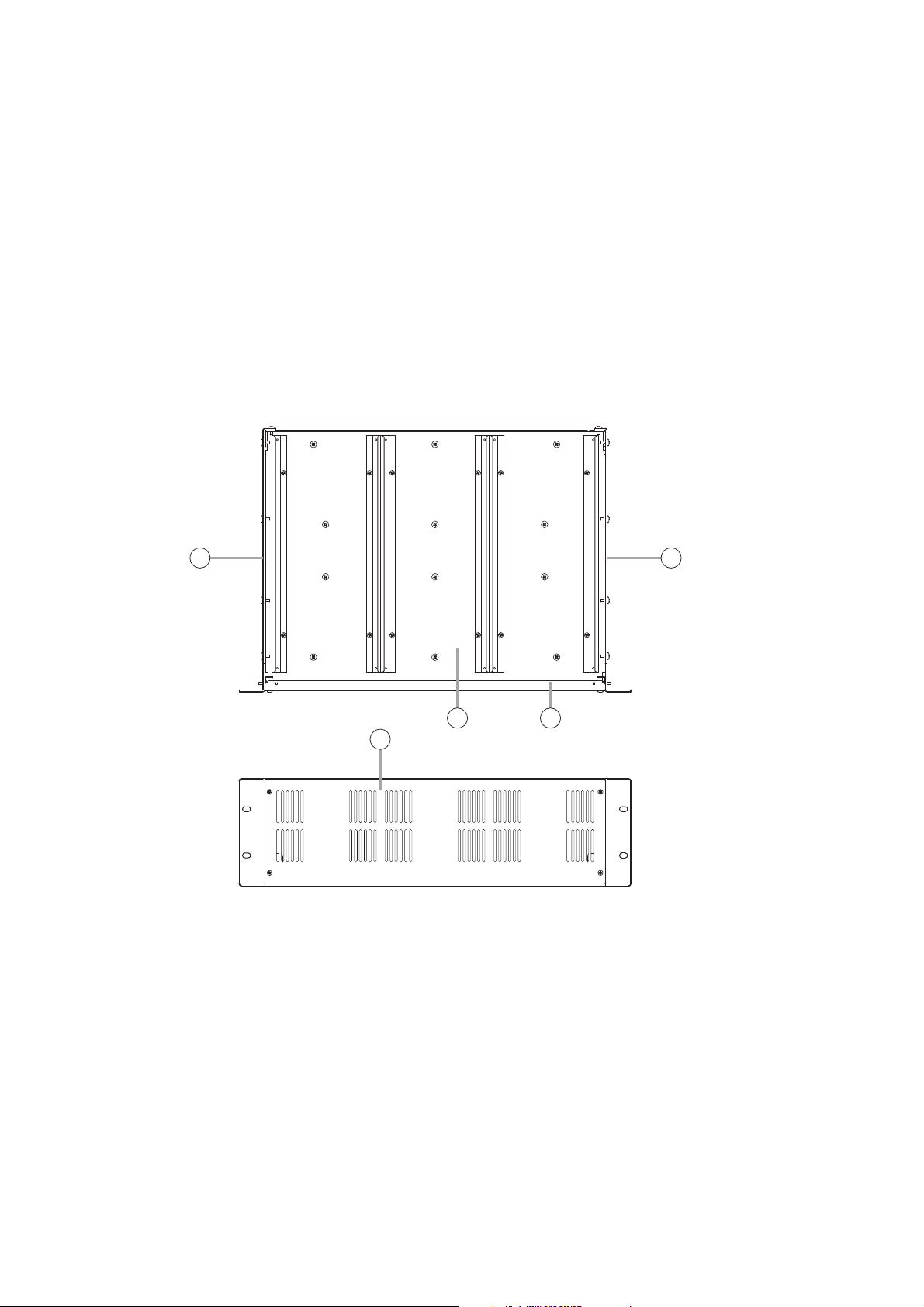
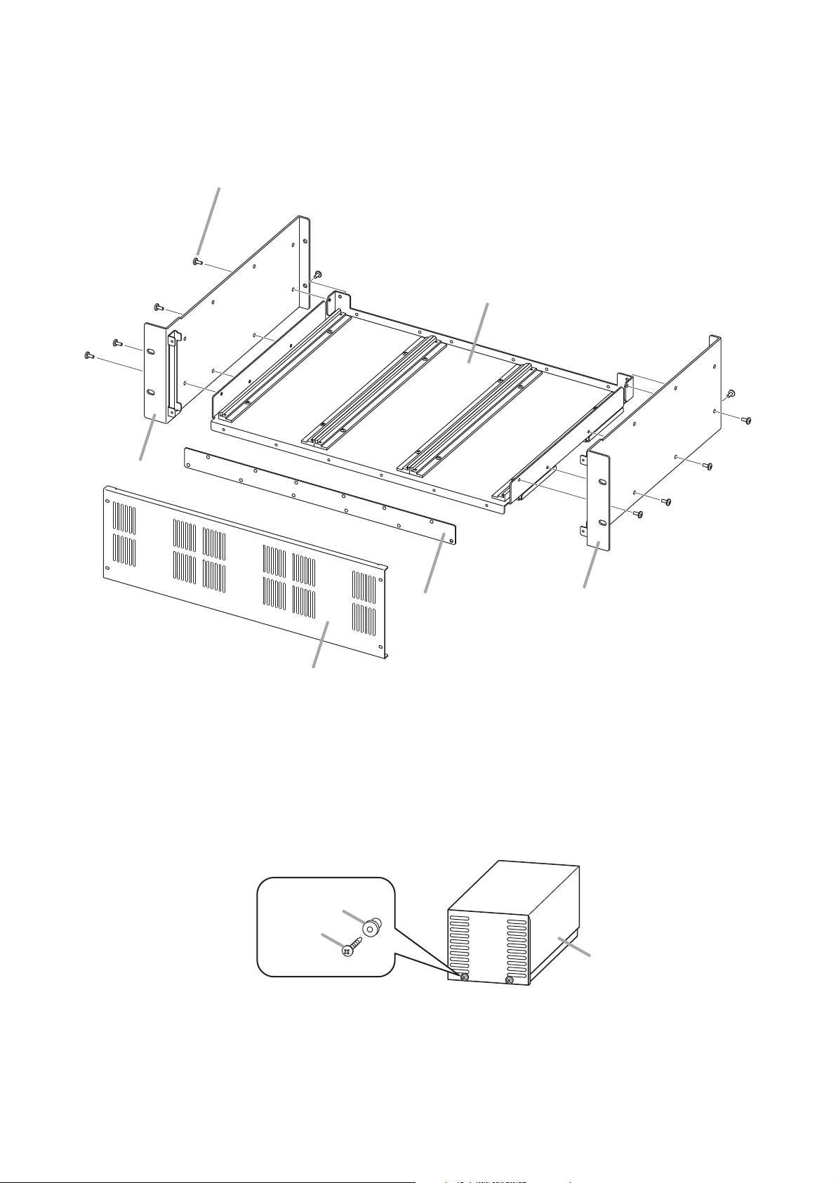
2.3. VX-2000PF Power Supply Frame
[VX-2000PF Components]
This unit is comprised of the following components. For the component assembly, refer to p. 9.
1. Front panel .................................................................. 1
2. Side panel ................................................................... 2
3. Chassis (VX-200PS guide rails pre-mounted) ..............1
4. Fixing bracket* ..............................................................1
* The Fixing bracket is not supplied with the previous VX-2000PF.
(Refer to p. 9, "Installation Precautions.")
The VX-2000PF permits the VX-200PS Power Supply to be mounted in an equipment rack.
Up to 3 VX-200PS units can be installed in the VX-2000PF. Refer to p. 10 for the VX-200PS mounting
procedure.
[Top]
[Front]
2 2
3
4
1
Page 9
9
3. INSTALLATION
3.1. Assembling the VX-2000PF Power Supply Frame
Note: Mount the front panel and fixing bracket after installing the VX-200PS units on the chassis.
[Installation Precautions]
The VX-2000PF and VX-200PS units are slightly different in specifications between the previous and current
production lots.
The previous unit differs from the product explained in this manual in the following points.
Previous VX-2000PF: A Fixing bracket is not supplied.
Previous VX-200PS: A spacer is placed between the front panel and screw. (See the figure below.)
The mounting method for the combination of the current unit and previous unit differs from the steps shown on
the next page.
• When mounting the previous VX-200PS in the current VX-2000PF;
Use only the removed screws without using the spacers removed from the VX-200PS's front panel in Step 3.
• When mounting the VX-200PS (previous or current unit) in the previous VX-2000PF;
There is no need to secure the VX-200PS units using the screws in Steps 2, and 3.
Self-tapping screw 4 x 10
(supplied with the VX-2000PF)
Chassis
Side panel
Fixing bracket
Front panel
Spacer
Screw
Side panel
Previous VX-200PS
Page 10
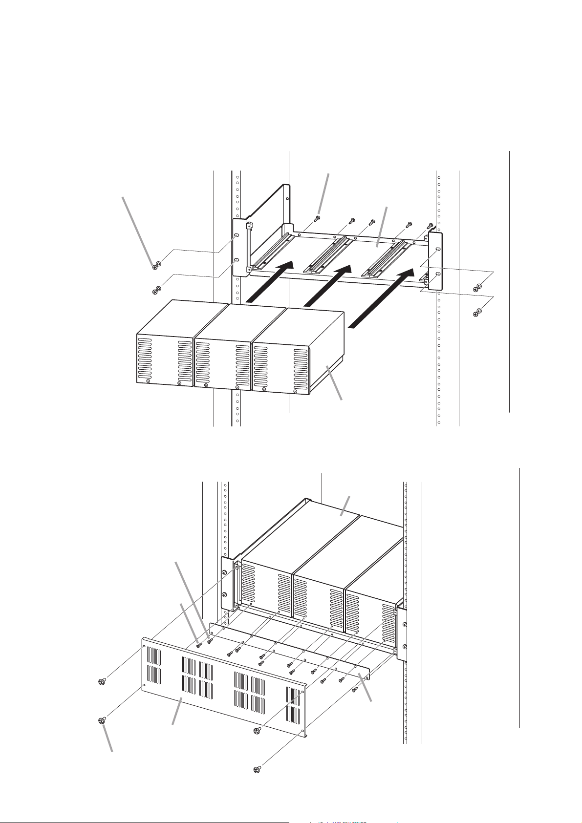
10
Step 3. Fit the VX-2000PF's fixing bracket and front panel in place.
3.2. Installing the VX-200PS Power Supply Unit in the VX-2000PF
To be compliant with EN 54-4, install the VX-2000DS and VX-2000PF in the CR cabinet rack series CR-15,
CR-22, CR-27, CR-35, CR-40, and CR-44.
Step 1. Mount the VX-2000PF in an equipment rack.
Step 2. Mount the VX-200PS in the VX-2000PF.
Self-tapping screw 4 x 10
(remove from VX-200PS'
rear panel)
Supplied with the VX-2000PF
or other appropriate screw
VX-2000PF
1
1
VX-200PS
Self-tapping screw 4 x 10
(remove from the VX-200PS'
front panel)
Self-tapping screw 4 x 10
(supplied with the VX-2000PF)
2
Rack
VX-200PS
Rack
VX-2000PF's
Fixing bracket
VX-2000PF's Front panel
Machine screw M3 x 6
(supplied with the VX-2000PF)
Page 11

11
3.3. Battery Installation
• Take special care to prevent the battery from being shorted by misconnection of the battery cable.
If the short occurs, the unit may fail.
Follow the instructions in this section for safe and secure connection.
• Be sure to switch off the system power before battery connection. For the procedure, refer to p. 28
"SWITCHING OFF SYSTEM POWER."
• After completing the battery connection, be sure to attach a terminal cover onto each battery
terminal to prevent shorts between positive and negative terminals.
WARNING
[Cable end treatment]
To secure the connection between the battery terminal and cable, be sure to use the cable of specified
diameter and treat its end as follows.
[Cautions on cable connection to the battery terminal]
• Before connecting the battery cable to the battery
terminal, be sure to fully open the cable clamp by
turning the terminal screw counterclockwise.
• Insert the battery cable into the correct position in the battery terminal referring to the terminal's cross
sectional diagrams below.
Usable cable diameter: AWG 6 – AWG 0 (1/0)
(Line resistance should be within 4 mΩ in total.)
Stripped length: 30 mm ± 5 mm
Cross sectional area: 16 – 50 mm
Battery terminal
Cable clamp
Terminal screw
Fully open. Too narrow to
2
Incorrect
clamp the cable
Correct position of the cable insertion Incorrect position of the cable insertion
Wrong insertion position of the cable or a forked
Cable conductor
Cable clamp
cable insertion causes poor contact or insufficient
connection tightness, making the cable come off
to possibly cause short-circuit accident.
Page 12

12
• Strip the cable end long enough (30 mm ± 5 mm) to
be fully clamped. Otherwise, its outer jacket
prevents the cable conductor from being tightly
secured, causing poor contact.
[Attaching the insulating sheet]
To prevent the battery cable from being shorted to the rear panel due to misconnection, attach the supplied
insulating sheet in place following the procedures below.
Step 1. Remove the screw indicated by the arrow.
Step 2. Put the supplied insulating sheet over the
battery terminals, and fix it with the removed
screw.
Note
Attach the supplied Attention label (German) onto the
current English label as required.
Note correct polarity (positive and negative orientation) when
connecting the power supply cord. Reversed polarity connections will
cause damage to the system.
CAUTION
[Connecting the Battery]
Notes
To avoid battery failure and charger failure, take care of the following points.
• If batteries not recommended by the manufacturer are used and a charger failure occurs, connect a resistor
of 18 kΩ (1/4 W) parallel to the batteries.
• Use the specified type of batteries and capacity.
Correct Incorrect
VX-2000DS
BATTERY POWER IN
24V MAX150A
WARNING
Take special care to prevent the battery from
being shorted by misconnection of the battery
cable. If the short occurs, the unit may fail.
Insulating sheet
Attention label
18 kΩ (1/4 W)
Battery Battery
Page 13

13
• Use the battery connection cables as short in length and as large in diameter as possible.
• Total resistance of the battery connection path should be less than 4 mΩ, which includes resistance of all of
wire, terminal, fuse, and terminal points.
For reference, refer to each resistance as follows.
Resistance of terminal, fuse (if provided): 1 – 2 mΩ
Resistance of terminal point: 0.1 – 0.5 mΩ
• Fasten the bolts, nuts, and screws of the unit's battery connection terminals and battery terminals with the
torque as shown below.
Step 1. Allow more than 10 seconds to elapse after removing the power cord from the VX-2000DS' rear-
mounted AC inlet.
Step 2. Insert the positive battery cable into the VX-2000DS' rear-mounted BATTERY POWER IN positive
terminal from the bottom side of the connector, then tighten the terminal screw with a flat screwdriver.
Note
Never connect the negative cable first to avoid battery short-circuit that occurs if the positive cable
should contact the unit chassis or equipment rack.
Step 3. Connect the negative battery cable to the negative terminal in the same manner as Step 2.
Tightening torque: 6 – 8 Nm
VX-2000DS
230V
50/60Hz 240W
DETECT(VX-200PS)
PS3 PS2
THERMISTOR
DS – SFFUSE
LINK
BATTERY POWER IN
24V MAX150A
OFFONON OFF
( ) ( )
DC POWER OUT (+) MAX 25A (DC 20V-40V)
PS IN (+) MAX 25A (DC20V-40V)
615432615432
( )
PS IN
1,2:PS1
3,4:PS2
5,6:PS3
Battery connnection terminals
Cable A
AWG 6
AWG 4
AWG 2
AWG 0 (1/0)
Battery
Cable cross
sectional area
2
16 mm
2
25 mm
2
35 mm
2
50 mm
Cable B
Battery
Length (2 mΩ)AWG
180 cm
280 cm
400 cm
570 cm
Cable C
Example of wire length
Cable A, Cable C Cable B
80 cm each
130 cm each
190 cm each
275 cm each
20 cm
20 cm
20 cm
20 cm
VX-2000DS’ Battery connection terminals
Battery terminals
6 – 8 Nm
4.1 – 5.6 Nm (M6)
8.2 – 5.6 Nm (M8)
VX-2000DS
B
A
TT
E
R
Y
P
O
W
E
R
I
N
2
4V M
A
X
15
0A
1
2
Page 14

14
[Installing a thermistor]
The thermistor located on the VX-2000DS' rear panel is designed to compensate for temperature changes
when charging the battery. It should be mounted on the side of one battery in between 2 batteries using
thermal insulating sheet to avoid ambient temperature change, thereby maintaining the temperature of the
thermistor relatively constant.
Step 1. Clean the exterior surface of the battery using a soft damp cloth.
Note
Avoid using chemical cleaners and solvents that may cause the battery cases to crack or leak.
Step 2. Follow the procedure shown above to attach the thermistor to the adhesive side of thermal insulating
sheet, then attach the sheet to the side of the battery.
Note
The thermal insulating sheet is extremely difficult to remove after attached.
Step 1. Confirm that battery power is not in use by means of the VX-2000DS' front-mounted BATTERY
POWER LED, which is unlit in this case.
Step 2. Loosen the VX-2000DS' BATTERY POWER IN negative terminal screw, then pull out the negative
battery cable.
Notes
• Never remove the positive cable first to avoid battery short-circuit that occurs if the positive cable
should contact the unit chassis or equipment rack.
• Insulate the exposed end of the removed cable with insulating tape to avoid shorting to the other
cable.
Step 3. Remove the positive battery cable from the positive terminal in the same manner as Step 2.
Note
Insulate the exposed end of removed cable with insulating tape to avoid shorting to the other cable.
[Disconnecting the Battery]
Thermistor
Thermal insulating sheet
(supplied with the VX-2000DS)
VX-2000DS
Rack
Batteries
Page 15

15
[Fixing the battery] (ER/UK version only)
To comply with EN 54-4, fix the battery at the bottom plate surface of the rack as shown below.
Attach hook fasteners to the bottom surface of each battery, and loop fasteners to the bottom plate surface of
the rack.
3.4. Affixing Declaration of Compliance (EN 54-4 Standard, ER/UK version only)
To declare that the VX-2000DS, VX-2000PF, and VX-200PS comply with EN 54-4, affix the sticker supplied
with the VX-2000DS visible to the front panel of the equipment (e.g. at the upper right side as shown below).
Bottom of battery
[Viewed from the battery's bottom surface side]
Hook fasteners
(supplied with the VX-2000DS)
When replacing the batteries, 4 each of fastener hooks and loops, and a thermal insulating sheet listed
below are also required. Consult your nearest TOA dealer on how you can obtain them.
Part code Part name
135-01-075-2
135-01-076-3
131-27-891-2 VX-2000DS THERMAL INSULATING SHEET
VX-2000DS FASTENER HOOK (A)
VX-2000DS FASTENER LOOP (B)
Rack
VX-2000PF and
VX-200PS
VX-2000DS
EN 54-4
Sticker (supplied with the VX-2000DS)
Affix only the upper part of the
sticker to the equipment rack.
EN 54-4
Paste this sticker on the outside
of the cabinet rack containing
the so certified equipment.
Page 16

16
4. CONNECTIONS WHEN USING WITH THE VX-2000 SYSTEM
4.1. Connections between VX-2000DS and VX-200PS
(–)
DETECT(VX-200PS)
PS3
PS2
OFFONON OFF
VX-200PS VX-200PS
230V
50/60Hz
230 V AC
220 V AC
50/60 Hz
e
f
––
+
PS OUT
+
230V
50/60Hz
230 V AC
220 V AC
50/60 Hz
Turn the PS2 switch on when the
second VX-200PS unit is connected,
and the PS3 switch on when the
third unit is connected.
VX-200PS
c
d
––
PS OUT
+
+
230V
50/60Hz
230 V AC
220 V AC
50/60 Hz
Cable:
AWG 14 – AWG 10
(line resistance within
10 mΩ/pair)
a
b
––
+
PS OUT
+
VX-2000DS
230V
50/60Hz 240W
230 V AC
220 V AC
50/60 Hz
Cat. 5 STP
To VX-2000SF
DS–SF LINK 1, 2 connectors
Lead-acid
Battery
DETECT(VX-200PS)
PS3 PS2
OFFONON OFF
THERMISTOR
DS – SFFUSE
LINK
BATTERY POWER IN
24V MAX150A
( ) ( )
Lead-acid
Battery
DC POWER OUT (+) MAX 25A (DC 20V-40V)
( )
To DC inputs of the following units.
VX-2000/2000SF, VP-2064/2122/2241/2421
Cable:
AWG 6 – AWG 0 (1/0)
PS IN (+) MAX 25A (DC20V-40V)
615432615432
e
c
d
f
(–)
PS IN
1,2:PS1
3,4:PS2
5,6:PS3
a
b
RJ45 male connector
Caution
The charging current from VX-2000DS is 5 A maximum.
Applicable Batteries: Panasonic LC-X1265PG/APG
Page 17

17
4.2. Connecting the VX-2000DS to VX-2000 System
VX-2000
DATA LINK
a
From VX-2000DS
From VX-2000DS
From VX-2000DS
(+)
(–)
(+)
(–)
(+)
(–)
b
DC POWER IN
VX-2000SF
1
DS-SF
LINK
2
a
b
DC POWER IN
VP-2064, VP-2122, VP-2241, or VP-2421
DC POWER IN
28 V 4.8 A
a
b
CH4
CH
PA OUT (SP LINE)
CH3
CH
CH2
CH
CH1
CH
AUDIO LINK
OUT
CH3 CH1
CH4 CH2
From VX-2000DS
(+)
(–)
VP-2064, VP-2122, VP-2241, or VP-2421
DC POWER IN
28 V 4.8 A
CH4
CH
PA OUT (SP LINE)
CH3
CH
CH2
CH
CH1
CH
a
b
VX-2000DS (No. 1)
DS – SF
LINK
Cat. 5 STP
VX-2000DS (No. 2)
DS – SF
LINK
DC power
output terminals
(–)
CH3 CH1
CH4 CH2
a
DC POWER OUT (+) MAX 25A (DC 20V-40V)
615432615432
( )
b
PS IN (+) MAX 25A (DC20V-40V)
PS IN
1,2:PS1
3,4:PS2
5,6:PS3
Cat. 5 STP
RJ45 male connector
Page 18

18
5.1. Connections between VX-2000DS and VX-200PS
5. CONNECTIONS WHEN USING WITH THE SX-2000 SYSTEM
(–)
DETECT(VX-200PS)
PS3
PS2
OFFONON OFF
e
f
VX-200PS VX-200PSVX-200PS
PS OUT
+
+
230V
50/60Hz
230 V AC
220 V AC
50/60 Hz
230V
50/60Hz
230 V AC
220 V AC
50/60 Hz
––
Turn the PS2 switch on when the
second VX-200PS unit is connected,
and the PS3 switch on when the
third unit is connected.
c
d
––
PS OUT
+
+
230V
50/60Hz
230 V AC
220 V AC
50/60 Hz
Cable:
AWG 14 – AWG 10
(line resistance within
10 mΩ/pair)
a
b
––
+
PS OUT
+
VX-2000DS
230V
50/60Hz 240W
230 V AC
220 V AC
50/60 Hz
Cat. 5 STP
To SX-2000SM or SX-2100AO
DS LINK 1, 2 connectors
Lead-acid
Battery
Caution
The charging current from VX-2000DS is 5 A maximum.
Applicable Batteries: Panasonic LC-X1265PG/APG
DETECT(VX-200PS)
PS3 PS2
OFFONON OFF
THERMISTOR
DS – SFFUSE
LINK
BATTERY POWER IN
24V MAX150A
( ) ( )
Lead-acid
Battery
DC POWER OUT (+) MAX 25A (DC 20V-40V)
( )
To DC inputs of the following units.
SX-2000SM/2100AI/2000AO/2100AO
/2000CI/2000CO,
VP-2064/2122/2241/2421
Cable:
AWG 6 – AWG 0 (1/0)
PS IN (+) MAX 25A (DC20V-40V)
615432615432
e
c
d
f
(–)
PS IN
1,2:PS1
3,4:PS2
5,6:PS3
a
b
RJ45 male connector
Page 19

19
5.2. Connecting the VX-2000DS to SX-2000 System
[When using a redundant power system*]
In this connection example, 2 power supply units are used. Even if one of the 2 units fails or its power supply
line is broken, power is still supplied from the other unit, preventing the system from going down.
* A method of connecting separate power sources to each power input or connecting the commercial power
supply and backup power supply separately to each power input to prevent the system from going down
when a cable is broken or power fails.
4P removable terminal plug
(supplied with the SX-2000SM, SX-2100AI, SX-2000AO
SX-2100AO, SX-2000CI, and SX-2000CO)
(DC power input terminal)
Cable: AWG 18 – AWG 14
VX-2000DS
230V
50/60Hz 240W
DETECT(VX-200PS)
PS3 PS2
THERMISTOR
DS– SFFUSE
LINK
SX-2100AO or SX-2000AO
(The figure below shows the SX-2100AO.)
(DC power input terminal)
SX-2000SM
SX-2100AI
SX-2000CI
SX-2000CO
Power line B (+)
DC POWER OUT (+) MAX 25A (DC 20V-40V)
BATTERY POWER IN
24V MAX150A
( ) ( )
OFFONON OFF
DC POWER OUT (+) MAX 25A (DC 20V-40V)
PS IN (+) MAX 25A (DC20V-40V)
615432615432
( )
PS IN (+) MAX 25A (DC20V-40V)
615432615432
PS IN
1,2:PS1
3,4:PS2
5,6:PS3
( )
VX-2000DS
DETECT(VX-200PS)
230V
50/60Hz 240W
PS3 PS2
THERMISTOR
Power line B (–)
Power line A (+)
DC POWER OUT (+) MAX 25A (DC 20V-40V)
BATTERY POWER IN
24V MAX150A
( ) ( )
OFFONON OFF
DS– SFFUSE
LINK
DC POWER OUT (+) MAX 25A (DC 20V-40V)
PS IN (+) MAX 25A (DC20V-40V)
615432615432
( )
PS IN (+) MAX 25A (DC20V-40V)
615432615432
PS IN
1,2:PS1
3,4:PS2
5,6:PS3
( )
Power line A (–)
Page 20

20
[When not using a redundant power system]
Required power is supplied to the system from a single power supply unit. Connect the [+] terminal of Input A
to the [+] terminal of Input B, and the [–] terminal of Input A to the [–] terminal of Input B.
Note
When connecting 2 power cables to a single terminal of the removable
terminal plug, use a ferrule terminal with an insulation sleeve to crimp the
cables because such cable conductors could become loose.
Recommended "Phoenix Contact" ferrule terminals for power supply
cables
Crimping tool: CRIMPFOX UD6-4 (made by Phoenix Contact)
4P removable terminal plug
(supplied with the SX-2000SM, SX-2100AI,SX-2000AO,
SX-2100AO, SX-2000CI, and SX-2000CO)
(DC power input terminal) (DC power input terminal)
Cable: AWG 18 – AWG 14
DC POWER OUT (+) MAX 25A (DC 20V-40V)
SX-2100AO or SX-2000AO
(The figure below shows the SX-2100AO.)
SX-2000SM
SX-2100AI
SX-2000CI
SX-2000CO
PS IN (+) MAX 25A (DC20V-40V)
615432615432
VX-2000DS
230V
50/60Hz 240W
DETECT(VX-200PS)
PS3 PS2
THERMISTOR
DS – SFFUSE
LINK
BATTERY POWER IN
24V MAX150A
OFFONON OFF
( ) ( )
DC POWER OUT (+) MAX 25A (DC 20V-40V)
DC POWER IN
28 V 4.8 A
PS IN (+) MAX 25A (DC20V-40V)
615432615432
( )
VP-2064, VP-2122, VP-2241, or VP-2421
Model Number a
AI 1,5-8 BK
a
3.4 mm
1
AI-TWIN 2 x 1,5-8 BK 6.6 mm
2
a
3.6 mm
b
1.8 mm
1
l
14 mm
16 mm2.3 mm
2
l
8 mm
8 mm
PS IN
1,2:PS1
3,4:PS2
5,6:PS3
( )
DC POWER IN
28 V 4.8 A
PA OUT (SP LINE)
CH
CH1CHCH2CHCH3CHCH4
CH3 CH1
CH4 CH2
Insulation sleeve
Contact section
a
2
l
1
l
bb
Insulation sleeve
1
a
Contact section
2
a
2
l
1
l
Page 21

21
5.3. DS Link Terminal Connections
Connect the DS-SF LINK terminal of the VX-2000DS to the DS Link terminal of the SX-2000SM or SX2100AO. The figure below shows a connection example when the VX-2000DS units are connected to the SX2100AO. This connection also applies to the SX-2000SM.
SX-2100AO
VX-2000DS (No. 1)
230V
50/60Hz 240W
T3.15A L
Control connector
VX-2000DS (No. 2)
230V
50/60Hz 240W
T3.15A L
DETECT(VX-200PS)
PS3 PS2
OFFONON OFF
THERMISTOR
DS – SF
LINK
DS – SFFUSE
DS – SF
LINK SETTING
DETECT(VX-200PS)
PS3 PS2
OFFONON OFF
THERMISTOR
DS – SF
LINK
DS – SFFUSE
DS – SF
LINK SETTING
DCAC
DCAC
BATTERY POWER IN
24V MAX150A
( ) ( )
BATTERY POWER IN
24V MAX150A
( ) ( )
DS Link Terminals
DC POWER OUT (+) MAX 25A (DC 20V-40V)
( )
DC POWER OUT (+) MAX 25A (DC 20V-40V)
( )
PS IN (+) MAX 25A (DC20V-40V)
615432615432
PS IN (+) MAX 25A (DC20V-40V)
615432615432
Applicable cable: Cat. 5 STP
(Category 5 shielded twisted pair cable)
PS IN
1,2:PS1
3,4:PS2
5,6:PS3
PS IN
1,2:PS1
3,4:PS2
5,6:PS3
Control connector
Page 22

22
6. CONNECTIONS WHEN USING WITH THE VM-3000 SYSTEM
230 V AC
220 V AC
50/60 Hz
From VX-2000DS
230 V AC
220 V AC
50/60 Hz
VM-3240VA/3360VA
VP-2241
(+)
c
(–)
d
VM-3240E/3360E
DC POWER IN
28 V 4.8 A
(–)(–)(+)(+)
PA OUT (SP LINE)
CH
(–)(–)(+)(+)
Cable: AWG 10 – AWG 8
From VX-2000DS
c
d
d
Note
a
Remove the short bar attached at the factory.
PA LINK VP-200VX
From VX-2000DS
c
d
d
Cable: AWG 10 – AWG 8
b
VP-2241
DC POWER IN
From VX-2000DS
(+)
(–)
28 V 4.8 A
c
d
PA OUT (SP LINE)
CH
See “Note” below.
VX-2000DS
DETECT(VX-200PS)
PS3 PS2
OFFONON OFF
THERMISTOR
DS – SFFUSE
LINK
230 V AC
220 V AC
230V
50/60Hz 240W
50/60 Hz
Cat. 5 STP
Cable:
Caution
AWG 6 – AWG 0 (1/0)
The charging current from the
VX-2000DS is 5 A maximum.
Applicable Batteries:
Panasonic LC-X1265PG/APG
Note
Make PS2 and PS3 switch settings according to the total number of
connected power supply units VX-200PS and VM-3240VA/3360VA
(power supply unit incorporated); set PS2 to ON for 2 units, and PS2
and PS3 to ON for 3 units.
Note that these power supply units should be connected to the PS IN
(+) terminals 1 and 2 for the 1st unit, 3 and 4 for the 2nd unit, and 5
and 6 for the 3rd unit.
Lead-acid Battery
DC power
output terminals
BATTERY POWER IN
24V MAX150A
( ) ( )
c
DC POWER OUT (+) MAX 25A (DC 20V-40V)
( )
(–)
d
Cable:
AWG 14 – AWG 10
(line resistance within
10 mΩ/pair)
230 V AC
220 V AC
50/60 Hz
PA LINK VP-200VX
DC power
a
b
PS IN (+) MAX 25A (DC20V-40V)
615432615432
input terminals
VX-200PS
RJ45 male connector
PS IN
1,2:PS1
3,4:PS2
5,6:PS3
Page 23

23
Below is an example showing that one VX-2000DS is used in a system including 3 VM amplifiers.
Number of VM amplifiers 1 2 3 4 5 6 7 8 9 10
Number of VX-2000DS units 1 2 3 4
[Required number of VX-200PS and VX-2000DS units]
The required number of the VX-2000DS Emergency Power Supply units and VX-200PS Power Supply Units
are determined depending on the application of the system configured with the VM-3240VA, VM-3360VA, VM3240E, and VM-3360E (hereinafter called "VM amplifier"), and/or the VP-2241 and VP-2421 (hereinafter
called "VP amplifier").
•
Required number in a 1-channel broadcasting system
System including VM amplifiers only
One VX-2000DS is required every 3 VM amplifiers. The VX-200PS is not needed in this system.
VM-3240VA
VX-2000DS
Lead-acid Battery
VM LINK
VM-3240E
VM LINK
DS LINK
VM-3240E
DC POWER
Page 24

24
System including one VP amplifier connected as a standby amplifier
One VX-2000DS is required every 3 VM amplifiers.
Note
Connect the VX-200PS to the VX-2000DS to
which the VP amplifier is connected.
Number of VM amplifiers 1 2 3 4 5 6 7 8 9 10
Number of VX-2000DS units 1 2 3 4
Number of VX-200PS units 0 1
Below is an example showing that 2 VX-2000DSs and 1 VX-200PS are used in a system including 4 VM
amplifiers.
VM-3240VA
VX-2000DS
Lead-acid Battery
VX-2000DS
Lead-acid Battery
VX-200PS
DS LINK
DC POWER
DS LINK
DC POWER
EXT. AMP
INPUT
EXT. AMP
INPUT
EXT. AMP
INPUT
VM LINK
EXT. PA LINK
DC POWER
VM LINK
VM LINK
EXT. AMP INPUT
PA OUT
VP-2241
PA OUT
VM-3240E
VM-3240E
VM-3240E
Page 25

25
Number of VM amplifiers 1 2 3 4 5 6 7 8 9 10
Number of VX-2000DS units 1 2 3 4 5
Number of VX-200PS units 1 2 3 4 5
Below is an example showing that 2 each of VX-2000DSs and VX-200PSs are used in a system including 3
VM amplifiers.
Notes
•
A pair of the VM amplifier and VP amplifier should be connected to the same VX-2000DS.
•
One VX-200PS should be connected to each VX-2000DS.
•
Required number of VX-2000DS and VX-200PS units in a BGM/Paging system
One each of the VX-2000DS and VX-200PS is required every 2 VM amplifiers.
VM-3240VA
VX-2000DS
Lead-acid Battery
VX-200PS
VX-200PS
DS LINK
DC POWER
VM LINK
EXT. PA LINK
DC POWER
VM LINK
EXT. PA LINK
DC POWER
EXT. AMP INPUT
PA OUT
VM-3240E
EXT. AMP INPUT
PA OUT
VM-3240E
VP-2241
VP-2241
EXT. AMP INPUT
VX-2000DS
Lead-acid Battery
DS LINK
DC POWER
EXT. PA LINK
DC POWER
PA OUT
VP-2241
Page 26

26
[VX-2000DS]
AC IN 3P inlet
–
Supplied cable
–
230 V AC, 50/60 Hz
220 V AC, 50/60 Hz
––
[VX-200PS]
AC IN 3P inlet
–
Supplied cable
–
230 V AC, 50/60 Hz
220 V AC, 50/60 Hz
––
DS-SF LINK RJ45 (female) RJ45 (male) Cat. 5 STP RJ45 (male) VX-2000SF DS-SF LINK RJ45 (female)
BATTERY
POWER IN
Screw terminal
Unprocessed cable
end
AWG 6 – AWG 0 (1/0)
16 – 50 mm
2
(line resistance
within 4 mΩ/total)
Unprocessed cable
end
Lead-acid battery
Electrode
(+, –)
–
PS IN Screw terminal
Round terminal
AWG 14 – AWG 10
2.0 – 5.5 mm
2
(line resistance
within 10 mΩ/pair)
Round terminal
VX-200PS PS OUT Screw terminal
PS OUT Screw terminal
Round terminal
AWG 14 – AWG 10
2.0 – 5.5 mm
2
(line resistance
within 10 mΩ/pair)
Round terminal
VX-2000DS PS IN Screw terminal
DC POWER
OUT
Screw terminal
Round terminal
–
Round terminal
VX-2000
VX-2000SF
VP-2064/2122/2241
/2421
DC POWER
IN
2P screw terminal
Terminal
Name
Equipment
Receptacle
Plug Cable Type Plug Equipment
Terminal
Name
Equipment
Receptacle
Terminal to Connect Cable Type Equipment to be Connected to
Terminal
Name
Equipment
Receptacle
Plug Cable Type Plug Equipment
Terminal
Name
Equipment
Receptacle
Terminal to Connect Cable Type Equipment to be Connected to
DC plug
(Outer diameter:
F5.5 mm
Inner diameter:
F2.1 mm
Length: 9.5 mm)
RM-200X
RM-200SA
RM-200M
DC IN
DC jack
AWG 24 – AWG 12
0.2 – 3.5 mm
2
Unprocessed cable
end
RM-200XF
LINK
(DC Power
In +/)
9P plug-in screw
terminal
7. CABLE USAGE TABLE
AWG 18 – AWG 14
0.8 – 2.0 mm
2
AWG 18 – AWG 14
0.8 – 2.0 mm
2
Round terminal
SX-2000SM
SX-2100AI
SX-2000AO
SX-2100AO
SX-2000CI
SX-2000CO
DC POWER
IN
4P removable
terminal plug
Round terminal
VM-3240VA
VM-3360VA
VM-3240E
VM-3360E
DC POWER
IN
2P screw terminal
AWG 10 – AWG 8
5.5 – 8.0 mm
2
AWG 24 – AWG 12
0.2 – 3.5 mm
2
Round terminal
RM-200SF
RM-300MF
DC IN 24 V Screw terminal
• VX-2000DS
Connector Name
DS-SF Link
'
DS-SF LINK Connections
RJ45 Pin No.
1
2
3
4
5
6
7
8
Shield
Orange/white
Orange
Green/white
Blue
Blue/white
Green
Brown/white
Brown
Shield
Colour Pair Assignment Direction/Level
Connection Check
Battery Failure
Charging Circuitry Failure
Output/0 – 3.3 V
DC Off
AC Off
3.3 V DC Input
Input (DC)/3.3 V
NC
Battery Check Activation
Input/0 – 3.3 V
Chassis GND
Page 27

27
The VX-2000DS can be used with the VM-2000 series system or other systems as a backup power supply
unit which supplies battery power to the system when AC mains fail.
To permit the VX-2000DS operation in this system configuration, shift the VX-2000DS' rear-mounted Setting
switch to the AC position (factory-preset to the DC position).
[Setting and connection example for the VX-2000 system]
8. USING THE VX-2000DS EXCLUSIVELY AS A BACKUP POWER SUPPLY
Note: Internal setting change is required. Leave this work to service personnel. Contact your TOA dealer.
VM-2240
230 V AC
220 V AC
50/60 Hz
230 V AC
220 V AC
50/60 Hz
VX-2000DS
230V
50/60Hz 240W
SETTING
DCAC
Setting switch
To DC (+) inputs of the VM-2000 series
system or other systems
SETTING
BATTERY POWER IN
24V MAX150A
( ) ( )
DETECT(VX-200PS)
PS3 PS2
OFFONON OFF
THERMISTOR
DS – SFFUSE
LINK
Note
Be sure to leave these
terminals unconnected.
PS IN
1,2:PS1
3,4:PS2
5,6:PS3
( )
To DC (–) inputs of the VM-2000 series
system or other systems
Lead-acid
Battery
Lead-acid
Battery
Caution
The charging current from VX-2000DS is 5 A maximum.
Applicable Batteries: Panasonic LC-X1265PG/APG
Page 28

28
When the system power (DC) needs to be switched off in such cases as maintenance or unit configuration
change, shift the Setting switch on the VX-2000DS to the "AC" position following the procedure below.
9. SWITCHING OFF SYSTEM POWER (DC)
Step 1. Terminate all current broadcasts to stop system operation.
Step 2. Shift the Setting switch on the VX-2000DS rear panel to the "AC" position.
Step 3. Stop the AC power supply to the VX-200PS.
This permits the system power to be switched off without switching over to battery operation.
Note
Never stop the AC power supply to the VX-2000DS as doing so causes the system power source to
be maintained by the battery.
[To restore the power supply to the system]
Step 1. Restore the AC power supply to the VX-200PS.
The DC power is supplied from the VX-200PS to the VX-2000DS.
Step 2. Shift the Setting switch on the VX-2000DS rear panel back to the "DC" position.
Step 3. Operate the system normally.
[To switch off the system power]
VX-2000DS
230V
50/60Hz 240W
DETECT(VX-200PS)
PS3 PS2
OFFONON OFF
THERMISTOR
DS – SFFUSE
DS – SF
LINK SETTING
BATTERY POWER IN
24V MAX150A
( ) ( )
DC POWER OUT (+) MAX 25A (DC 20V-40V)
PS IN (+) MAX 25A (DC20V-40V)
615432615432
( )
PS IN
1,2:PS1
3,4:PS2
5,6:PS3
T3.15A L
DCAC
SETTING
DCAC
Setting switch
Page 29

29
10. BLOCK DIAGRAM
Control Connector
[DS-SF LINK]
AC Mains
50/60 Hz
Fuse
250 V AC
T3.15 A L
Voltage
Checker
BATTERY
CONNECT Indicator
MAIN
POWER
Charging
NO
NC
NC
NO
Circuit
Delay
NC
CHARGING
Battery
Check Switch
NO
BATTERY
POWER
Control Circuit
NC
NC
NO
Fuse
7.5 A
DC Detect
NO
NO
NO
NO
NO
NO
Fuse
40 A
Fuse
40 A
Fuse
40 A
Fuse
40 A
Fuse
40 A
Fuse
40 A
DC Input [PS IN]
(150 A max.)
DC Input 1
DC Input 2
DC Input 3
DC Input 4
DC Input 5
DC Input 6
Battery Connection
Terminal
[BATTERY POWER IN]
[DC POWER OUT]
DC Output 1
DC Output 2
DC Output 3
DC Output 4
DC Output 5
DC Output 6
When battery voltage drops
below the reference voltage
BATTERY
CHECK Indicator
CPU
Page 30

30
11. SPECIFICATIONS
11.1. VX-2000DS Emergency Power Supply
230 V AC (ER/UK), 220 – 230 V AC (SA), 50/60 Hz
240 W max.
Panasonic LC-X1265PG/APG (65 Ah)
Trickle charging
5 A max.
27.3 V ±0.3 V (at 25°C)
Temperature correction coefficient: –40 mV/°C
6, M4 screw terminal, distance between barriers: 11 mm
6 (25 A max. each), M4 screw terminal, distance between barriers: 11 mm
RJ45 female connector for connecting the VX-2000SF Surveillance Frame
Twisted-pair straight cable (TIA/EIA-568A standard)
Type of control signal: Battery check, AC power status, DC power status,
charging circuit failure, and battery failure
1 pair of positive and negative terminals
Applicable cable diameter: AWG 6 – AWG 0 (1/0) (Line resistance within
4 mΩ/total)
Cross sectional area: 16 – 50 mm
2
0 to +40°C
Panel: Surface-treated steel plate, black (30% gloss), paint
482 (w) x 88.4 (h) x 377.6 (d) mm
10.5 kg
Power Source
Power Consumption
Applicable Battery
Charging Method
Charging Current
Charging Output Voltage
Power Supply Input
DC Power Output
Control Connector
Battery Connection
Operating Temperature
Finish
Dimensions
Weight
• Accessories
Rack mounting screw (5 x 12) .................... 4
Fiber washer .............................................. 4
Blade fuse (40 A) ....................................... 3
Fuse (T3.15 A L) ........................................ 1
Insulating sheet .......................................... 1
Attention label (German) ............................ 1
Thermal insulating sheet ............................ 1
Power cable (2 m) ...................................... 1
(ER/UK version only)
Fastener hook ............................................ 4
Fastener loop ............................................. 4
Sticker (Declaration of compliance) ........... 1
Note: The design and specifications are subject to change without notice for improvement.
Blade fuse (40 A), Blade fuse (7.5 A), Fuse (7.5 A)
43.5 A
50 mΩ
43.5 A
43.5 A
0 A
Twisted-pair straight cable (TIA/EIA-568A standard)
Fuse ratings
Maximum output current draw from the battery
Maximum internal resistance of the battery and its
associated circuitry, Ri max
Rated maximum continuous output current, I max a
Rated maximum short duration output current, I
max b
Rated minimum output current, I min
Recommended cable parameter for DS-SF Link
Page 31

31
11.3. VX-2000PF Power Supply Frame
Panel: Surface treated steel plate, black (30% gloss), paint
483 (w) x 132.6 (h) x 324.8 (d) mm
5.5 kg
Side Panel ..... 2, Front panel .....1, Chassis ..... 1, Fixing bracket* ..... 1
VX-200PS (up to 3)
Finish
Dimensions
Weight
Product Composition
Usable Unit
• Accessories
Self-tapping screw (4 x 10) ...................... 16
Machine screw M3 x 6 ............................... 4
Rack mounting screw (5 x 12) .................... 4
Fiber washer .............................................. 4
11.2. VX-200PS Power Supply Unit
230 V AC (ER/UK), 220 – 230 V AC (SA), 50/60 Hz
580 W
Rated output: 210 W (29 V, 7.25 A) x 2
Peak output: 400 W x 2
M4 screw terminal, distance between barriers: 11 mm
Applicable cable diameter: AWG 14 – AWG 10 (line resistance within
10 mΩ/pair)
Cross sectional area: 2.0 – 5.5 mm
2
Max. 4 V
0 to +40°C
VX-2000PF
Surface-treated steel plate
135 (w) x 118.2 (h) x 333.8 (d) mm
13.2 kg
Power Source
Power Consumption
DC Power Output
Ripple Voltage at Imax B
(at VX-2000DS's DC Output)
Operating Temperature
Applicable Frame
Finish
Dimensions
Weight
• Accessories
Fuse (T3.15 A L) ........................................ 1
Power cable (2 m) ...................................... 1
Note: The design and specifications are subject to change without notice for improvement.
* The Fixing bracket is not supplied with the previous VX-2000PF. (Refer to p. 9, "Installation Precautions.")
Note: The design and specifications are subject to change without notice for improvement.
Page 32

133-02-00147-00
URL: http://www.toa.jp/
Traceability Information for Europe
Manufacturer:
TOA Corporation
7-2-1, Minatojima-Nakamachi, Chuo-ku, Kobe, Hyogo,
Japan
Authorized representative:
TOA Electronics Europe GmbH
Suederstrasse 282, 20537 Hamburg,
Germany
 Loading...