

Page 1

Система оповещения TOA VX-2000 | toa.com.ua
System Design Guide for
Page 2

Contents
2
1. General Description
.................................................................................................... 1-1
2. System Features
.......................................................................................................... 2-1
3. Maximum System Examples
3.1. Block Diagram .............................................................................................................. 3-1
3.2. Maximum System Configuration Table ......................................................................... 3-2
4. Specifications
4.1. Fireman's Microphone RM-200XF .............................................................................. 4-1
4.2. Remote Microphone RM-200X ................................................................................... 4-2
4.3. Remote Microphone Extension RM-210 ..................................................................... 4-3
4.4. System Manager VX-2000 ......................................................................................... 4-4
4.5. Remote Microphone Input Module VX-200XR ........................................................... 4-5
4.6. Audio Input Module with Control input VX-200XI ....................................................... 4-6
4.7. Voice Announcement Board EV-200 .......................................................................... 4-7
4.8. Surveillance Frame VX-2000SF ................................................................................. 4-8
4.9. Impedance Detection Module VX-200SZ ................................................................... 4-9
4.10. Pilot Tone Detection Module VX-200SP .................................................................. 4-10
4.11. Control Input Module VX-200SI ................................................................................ 4-11
4.12. Control Output Module VX-200SO ........................................................................... 4-12
4.13. Equaliser Card VX-200SE ........................................................................................ 4-13
4.14. Power Amplifier 4 x 60 W VP-2064 ......................................................................... 4-14
4.15. Power Amplifier 2 x 120 W VP-2122 ....................................................................... 4-15
4.16. Power Amplifier 1 x 240 W VP-2241 ....................................................................... 4-16
4.17. Power Amplifier 1 x 420 W VP-2421 ....................................................................... 4-17
4.18. Power Amplifier Input Module VP-200VX ................................................................. 4-18
4.19. Power Supply Unit VX-200PS .................................................................................. 4-19
4.20. Emergency Power Supply VX-2000DS .................................................................... 4-20
4.21. Power Supply Frame VX-2000PF ............................................................................ 4-21
5. Typical System Examples
5.1. Typical System Outline
5.1.1. External View of the Building .............................................................................. 5-1
5.1.2. Internal Wiring ................................................................................................... 5-2
5.1.3. Block Diagram ................................................................................................... 5-3
5.1.4. Equipment Rack Conceptual Drawing ............................................................... 5-5
5.2. Equipment Interconnection Examples
5.2.1. VX-2000 Connections to Remote Microphones and Input Source Equipment ... 5-6
5.2.2. Connections between VX-2000 and VX-2000SF ............................................... 5-7
5.2.3. SF Modules (VX-200SP, VX-200SZ, VX-200SI, VX-200SO) Connections ........ 5-8
5.2.4. Connections Between VX-2000SF and Standby Amplifier ............................... 5-11
5.2.5. Connections Between VX-2000SF and VX-2000DS ........................................ 5-12
5.2.6. Connections Between VX-2000DS and VX-2000PS ........................................ 5-13
5.2.7. VX-2000 Cable Usage Table ............................................................................ 5-14
5.2.8. 5.2.8. VX-2000DS Cautions on Cable Connection to the Battery Terminal....... 5-17
Page 3

Contents
5.3. Settings
5.3.1. PC Hardware Requirements ............................................................................. 5-17
5.3.2. Offline Settings ................................................................................................. 5-18
5.4. Installation
5.4.1. Online Settings ................................................................................................. 5-21
5.4.2. Connections Between VX-2000 and PC .......................................................... 5-22
5.4.3. System File Download ...................................................................................... 5-23
5.4.4. Equipment Configuration Check ....................................................................... 5-24
5.4.5. SF Initialisation and Equipment Interconnection Check ................................... 5-26
5.4.6. Introduction of Other Functions
5.4.6.1. Reading Logs
(1) Loading Logs ................................................................................. 5-29
(2) Storing Logs ................................................................................... 5-31
(3) Printing Logs .................................................................................. 5-31
5.4.6.2. Printing Out System File Settings
(1) Printing Out .................................................................................... 5-32
(2) Printout Examples .......................................................................... 5-33
5.5. System Operation
5.5.1. Emergency Mode Operation (EV Single-source Sequence) ............................ 5-53
5.5.2. Remote Microphone Operation Examples
5.5.2.1. Emergency Mode Activation and Restoration ..................................... 5-55
(1) From Emergency Mode Activation to Restoration ......................... 5-56
(2) Making a microphone restoration announcement after returning
to general-purpose broadcast mode by pressing the Emergency
Restoration key. ............................................................................. 5-58
5.5.2.2. General-Purpose Broadcast ................................................................ 5-61
(1) Making Microphone Announcements ............................................. 5-63
(2) Changing the Base Pattern ............................................................ 5-64
(3) Changing Sound Volume ............................................................... 5-65
(4) Failure Indication ............................................................................ 5-67
5.6. Examples of Connections to the VM-2120 or VM-2240
(1) Systems Using the VX-200SP Pilot Tone Detection Module ................................ 5-71
(2) Systems Using the VX-200SZ Impedance Detection Module ............................... 5-73
(3) Using the SV-200M Surveillance Board with the VM-2122 or VM-2240 ............... 5-74
6. System Examples
6.1.School
6.1.1. External View of the school ................................................................................ 6-1
6.1.2. Internal Wiring .................................................................................................... 6-2
6.1.3. Block Diagram .................................................................................................... 6-3
6.2. Department Store
6.2.1. External View of the Building .............................................................................. 6-4
6.2.2. Internal Wiring .................................................................................................... 6-5
6.2.3. Block Diagram .................................................................................................... 6-6
6.2.4. Emergency Mode Operation (Dual-Origin EV Broadcasts) ................................ 6-7
3
Page 4

1. General Description
1. General Description
The TOA VX-2000 Series broadcast system is designed for both general-purpose and emergency broadcasts.
It is comprised of the System Manager, Surveillance Frame, Power Amplifiers, Power Supply unit, Emergency
Power Supply, and a user-specified number of Remote Microphones. The system complies with the EN60849
Standard and its failure detection circuitry operates continuously to check components and speaker lines for
any irregularities. If detected, failure warnings are provided by way of an LED indicator and a buzzer.
1-1
Page 5

2. System Features
2. System Features
Modular System Offers Connection to Various Sound Sources.
The VX-2000 System Manager features 8 input slots that permit the use of various input sources with the
selection of corresponding modules.
Up to 8 Remote Microphones Can Be Connected.
• A total of 8 RM-200X and RM-200XF Remote Microphones can be connected to the VX-2000. Up to 4 RM200XF units can be installed.
• RM-210 extension capability permits the number of Remote Microphone function keys to be increased to up
to 105 keys per unit.
• The system can be configured for up to 305 function key settings.
Sound Source Devices
• Up to 2 EV-200 units can be connected to the VX-2000.
• The VX-2000 features 4 different chime sound sources.
Standard-Equipment Control Input and Output
The VX-2000 features 16 control inputs and 16 control outputs as standard equipment.
Expansion to Up to 50 Output Zones
The VX-2000SF Surveillance Frame can be expanded to up to 5 units, increasing the number of available
output zones to up to 50 zones.
Control Input and Output Modules, and 2 Types of Speaker Output Modules
• The VX-2000SF is designed to accept up to 10 modules. The control input module, control output module,
and 2 types of speaker output modules are available.
• Speaker output modules feature failure-detection circuitry. Two failure detection methods are provided:
impedance checking and pilot signal monitoring. Such failure modes as speaker line shorts, open circuits
and ground faults can be detected.
• With the addition of extra control input modules and control output modules, the number of control inputs
and outputs can be expanded to up to a total of 128 terminals within the system. (Sixteen terminals are
included as standard equipment in the VX-2000.)
9-Band Graphic Equaliser Card
Provides 9 bands of computer-adjustable graphic equalisation to the system's speaker output module.
Standby Amplifier Function
A standby amplifier can be installed for each VX-2000SF to automatically provide substitute amplifier output
should the main power amplifier fail.
CPU OFF Switch
Enables broadcast from the RM-200XF Fireman's Microphones to all output zones even if the system's main
CPU fails.
2-1
Page 6

2. System Features
2. System Features
Individual Block Failure Detection Circuitry
• This failure detection function monitors cable connections between the Remote Microphones and the VX2000, between the VX-2000 and the VX-2000SF, between the VX-2000SF and the VP power amplifiers, and
between the VP power amplifiers and the speakers.
• The function detects and warns of such failure modes as blown fuses or overheating in the VP power
amplifier.
• Can detect and indicate failure of the VX-2000DS' charging circuitry, or battery irregularities.
Failure Indication
• The failure LED indicators for the VX-2000, VX-2000SF and Remote Microphone light when any failure is
detected within the system.
• The failure indication function can be assigned to the Remote Microphone. When assigned, the LEDs flash
and a buzzer is sounded if a failure is detected.
Monitoring Function
The sound output of a selected output zone can be monitored using the Remote Microphone's internal
speaker or the VX-2000's monitor output.
Time Schedule Function
• A weekly schedule can be programmed.
• Up to 40 specific day programs can be set for any desired date and time.
• A summertime period can be set by either the system's PC software or the VX-2000's Summertime Setting
switch.
Energy Saving Mode
Battery consumption can be reduced by using the VP power amplifier's standby function (since the entire
system's power consumption is reduced by putting unnecessary power amplifiers in standby mode).
PC Setting Software
PC software is used to select input and output equipment, or set priorities, broadcast patterns, items to be
activated, etc. Various functions can also be freely assigned to the Remote Microphone' s function keys.
PC Software Provides Versatile Auxiliary Operation
• The VX-2000's memory can log up to 2,000 events, which can be read into a PC.
• System block diagrams and individual equipment settings can be printed out using the VX-2000's PC
software.
• Remote Microphone function key names can be printed out and used as name labels.
• System configurations and connections can be checked during equipment installation.
• Inspection mode permits inspection of emergency broadcast equipment operations without actually making
broadcasts.
2-2
Page 7
3. Maximum System Examples
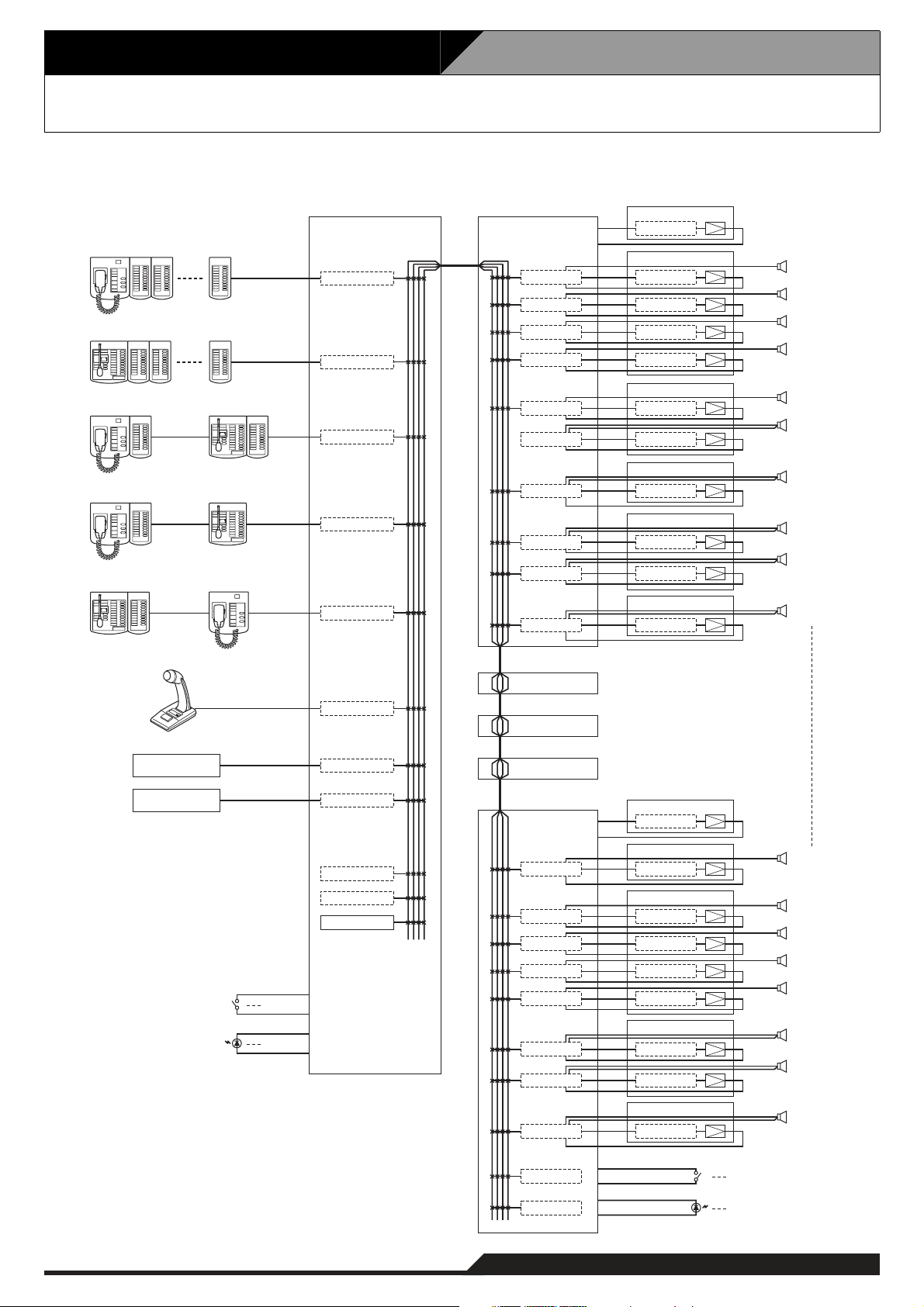
3.1. Block Diagram
The following block diagram shows the maximum size system that can be assembled with the VX-2000 Series.
RM-200XF + RM-210 x 10
RM-200X + RM-210 x 9
RM-200XF + RM-210 RM-200X + RM-210
RM-200XF + RM-210 RM-200X
RM-200X + RM-210 RM-200XF
VX-2000 VX-2000SF No.1
VX-200XR
VX-200XR
VX-200XR
VX-200XR
VX-200XR
VX-200SZ VP-200VX
VX-200SZ
VX-200SZ
VX-200SZ
VX-200SZ
VX-200SP
VX-200SP
VX-200SP
VX-200SP
VX-200SP
VP-2421
VP-200VX
VP-2064
VP-200VX
VP-200VX
VP-200VX
VP-2122
VP-200VX
VP-200VX
VP-2241
VP-200VX
VP-2122
VP-200VX
VP-200VX
VP-2421
VP-200VX
SF-1
Standby Amplifier
ZONE 1
ZONE 2
ZONE 3
ZONE 4
ZONE 5
ZONE 6
ZONE 7
ZONE 8
ZONE 9
ZONE 10
PM-660U
MD Player
CD Player
x 16
x 16
VX-200XI
U-01R
U-01R
EV-200 No.1
EV-200 No.2
Chime
Control Input x 16
Control Output x 16
VX-2000SF No.2
VX-2000SF No.3
VX-2000SF No.4
VX-2000SF No.5
VX-200SZ
VX-200SZ
VX-200SZ
VX-200SZ
VX-200SZ
VX-200SP
VX-200SP
VX-200SP
VP-2241
VP-200VX
VP-2241
VP-200VX
VP-2064
VP-200VX
VP-200VX
VP-200VX
VP-200VX
VP-2122
VP-200VX
VP-200VX
VP-2241
VP-200VX
SF-5
Standby Amplifier
ZONE 41
ZONE 42
ZONE 43
ZONE 44
ZONE 45
ZONE 46
ZONE 47
ZONE 48
VX-200SI
VX-200SO
x 16
x 16
3-1
Page 8

3. Maximum System Examples
3.2. Maximum System Configuration Table
Component
Input Source Equipment
RM-200XF
RM-200X
Paging Microphone and Music
Sources (MD, CD, etc.)
EV-200
Chime (built-in)
RM-200XF's and RM-200X's Function Key Extension
RM-210 10 units per RM-200XF
VX-2000
VX-2000 1 unit
Input Module
VX-200XR
VX-200XI
900 module
VX-2000SF
VX-2000SF 5 units
SF Module
VX-200SP 50 units
VX-200SZ 50 units
VX-200SI 7 units
VX-200SO 7 units
Optional Equaliser Card (to be installed in VX-200SP and VX-200SZ)
VX-200SE 50 units
Control Input
VX-2000
VX-200SI
Control Output
VX-2000
VX-200SO
Power Amplifier
VP-2064 (4 ch)
VP-2122 (2 ch)
VP-2241 (1 ch)
VP-2421 (1 ch)
Standby Amplifier 5 channels (1 channel per VX-2000SF)
Power Amplifier Input Module
VP-200VX 55 units in total of modules installed in Power and Standby Amplifiers
Power Supply
VX-2000DS 10 units 2 units per VX-2000SF
VX-200PS 30 units 2 units per VX-2000DS
Battery 40 units 2 or 4 units per VX-2000DS
4 units
8 units
8 units
2 units
1 unit
9 units per RM-200X
8 units in total of all Input Modules
Usable 900 modules: M-01F, M-01M, M-01P, M-51F, M-51S, M-61F, M-61S,
16 inputs
(as standard equipment)
112 inputs (7 units)
16 outputs
(as standard equipment)
112 outputs (7 units)
Note: The number and type of power amplifiers should be determined
depending on the required speaker output for each zone.
50 channels (50 zones)
Note: Necessary power capacity should be calculated based on total system
specifications.
Maximum No. of Units
8 units in total of
both models
315 function keys per system
U-01F, U-01P, U-01R, U-01S, and U-61S
50 units in total of all SF Modules
(10 units per VX-2000SF)
128 inputs in total
128 outputs in total
18 units in total of all
Input Source Equipment
3-2
Page 9
4-1
4. Specifications
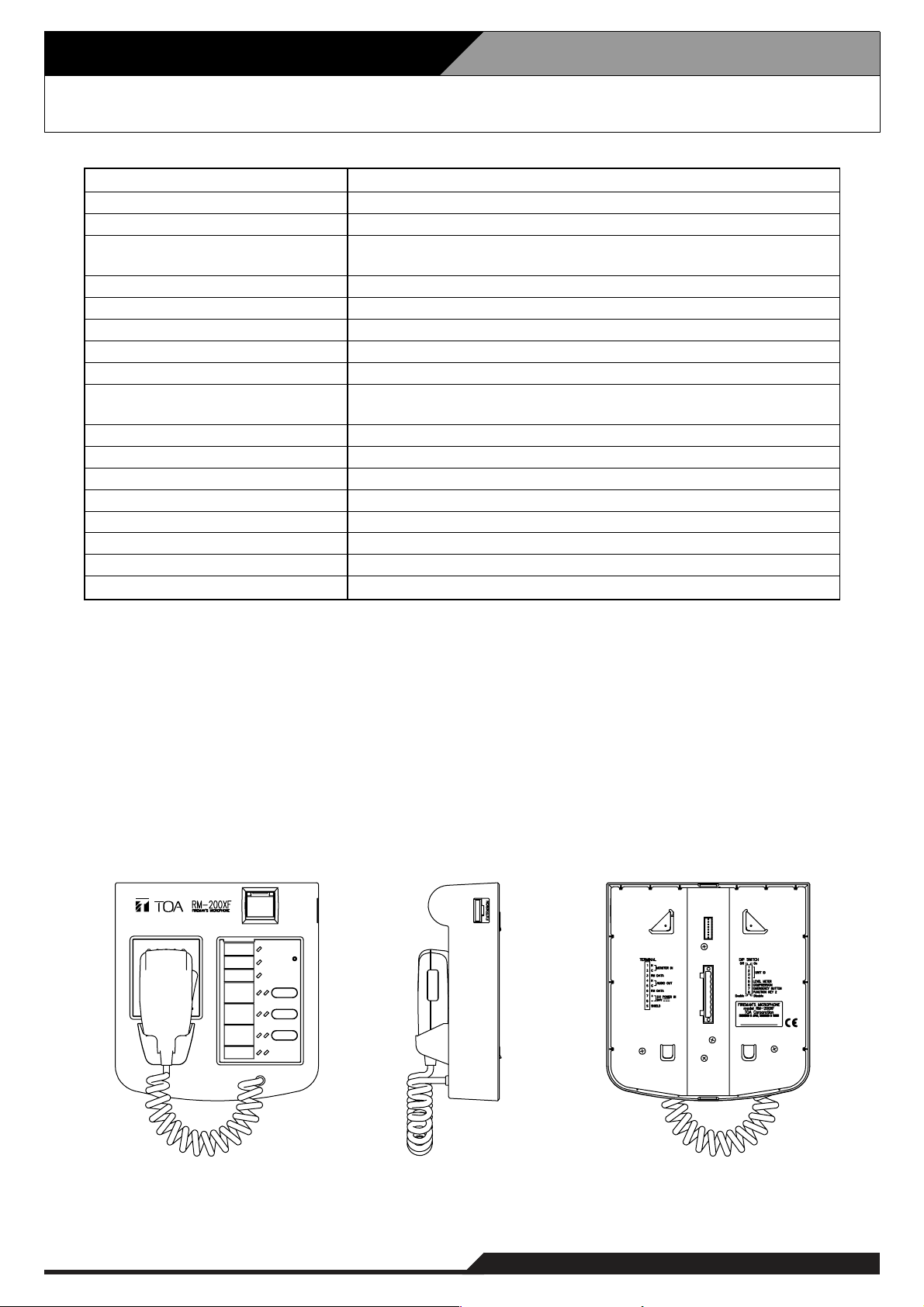
4.1. Fireman's Microphone RM-200XF
* 0 dB = 1 V
Note: LONWORKS is a trademark of Echelon Corporation.
• Accessory
Plug-in screw terminal ................................1
Wall mounting bracket ................................1
Wall mouting screw ....................................2
Box mounting screw ...................................2
(Applicable Box: YC-301, YS-11A)
24 V DC (Operating range: 16 – 40 V DC)
Under 200 mA (RM-200XF), 850 mA (with 10 RM-210s connected)
0 dB*, 600Ω, balanced
Dynamic microphone, Function switch (default: Press-to-talk),
Microphone element fault detection
Under 1%
200 – 15,000 Hz
Over 55 dB
200 mW
Microphone volume control, Monitor speaker volume control
5 (including Hand-held microphone's switch),
extendable up to 105 (with 10 RM-210s connected)
10 keys extension per RM-210, EXTENSION connector
4
LONWORKS twisted pair free topology transceiver
Category 5 STP cable, plug-in screw connector
500 m (Free topology wiring)
ABS resin, blueish gray (PANTONE 538 or its equivalent)
200 (w) x 215 (h) x 82.5 (d) mm (excluding the coiled cord)
1.2 kg
Power Source
Current Consumption
Audio Output
Hand-Held Microphone
Distortion
Frequency Response
S/N Ratio
Internal Monitor Speaker
Volume Control
Number of Function Keys
Key Extension
Number of Connectable Units
Communication System
Connection Cable and Connector
Communication Distance
Finish
Dimensions
Weight
[Top] [Bottom][Side]
Page 10
4. Specifications
4-2
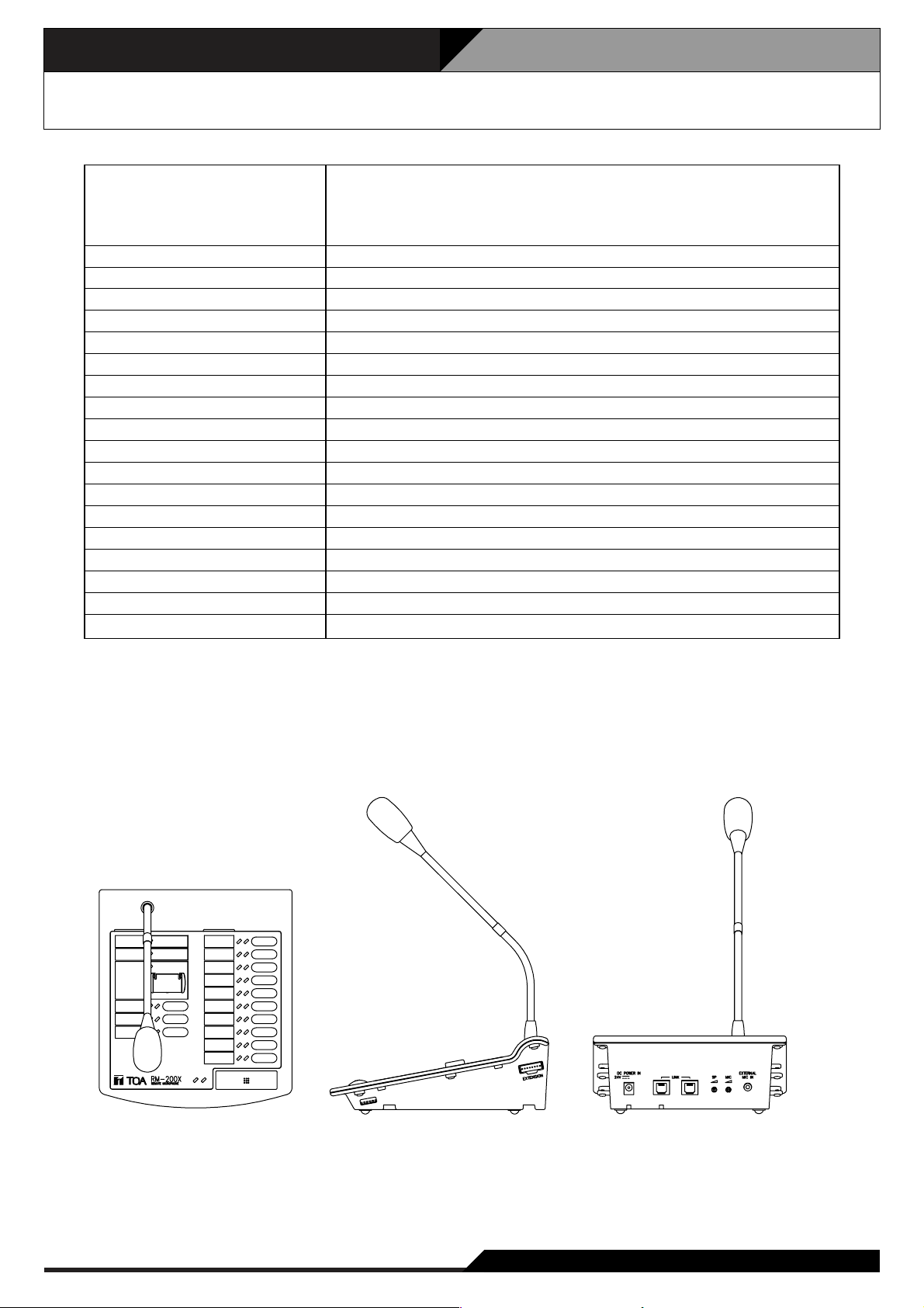
4.2. Remote Microphone RM-200X
* 0 dB = 1 V
Note: LONWORKS is a trademark of Echelon Corporation.
24 V DC (operating range: 16 – 40 V DC), supplied from RJ45 connector
or power input jack (non-polarity type)
Usable power input plug: 5.5 mm outer diameter, 2.1 mm inner diameter,
and 9.5 mm long
Under 200 mA (RM-200X), 750 mA (with 9 RM-210s connected)
0 dB*, 600Ω, balanced, RJ45 connector
Unidirectional electret condenser microphone
–40 dB*, 2.2kΩ, unbalanced, mini jack, phantom powering
Under 1%
100 – 20,000 Hz
Over 60 dB
200 mW
Microphone volume control, Monitor speaker volume control
15, extendable up to 105 (with 9 RM-210s connected)
10 keys extension per RM-210, EXTENSION connector
8 (include RM-200XF)
LONWORKS twisted pair free topology transceiver
Category 5 STP cable, RJ45 connector
500 m (Free topology wiring)
ABS resin, blueish gray (PANTONE 538 or its equivalent)
190 (W) x 76.5 (H) x 215 (D) mm (gooseneck microphone excluded)
850 g
Power Source
Current Consumption
Audio Output
Gooseneck Microphone
External Microphone Input
Distortion
Frequency Response
S/N Ratio
Internal Monitor Speaker
Volume Control
Number of Function Keys
Key Extension
Number of Connectable Units
Communication System
Connection Cable and Connector
Communication Distance
Finish
Dimensions
Weight
[Top] [Side] [Rear]
Page 11
4-3
4. Specifications
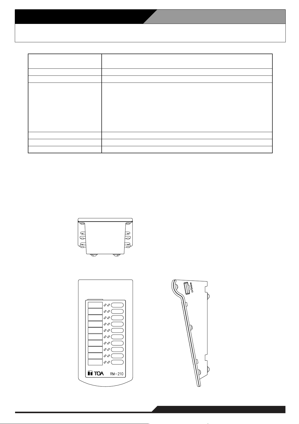
4.3. Remote Microphone Extension RM-210
• Accessories
Extension cable .......................................... 1
Linkage bracket A ...................................... 2
Linkage bracket B ...................................... 1
Screw for linkage bracket ......................... 12
Current Consumption
Connection
Number of Function Keys
Function
Finish
Dimensions
Weight
20mA max. (in terms of RM-200M's DC power input)
75mA max. (in terms of DC power inputs of RM-200X and RM-200XF)
Connection to RM-200M, RM-200X or RM-200XF by way of dedicated cable
10
When used to expand the RM-200M:
Selects and activates the Voice Announcement Board messages.
When used to expand the RM-200X and RM-200XF (PC software setting):
Emergency activation, emergency reset, BGM pattern selection,
EV message activation, broadcast zone selection,
monitor zone selection, chime activation, Talk switch activation,
control output activation, input volume adjustment,
zone volume adjustment, and failure output indication and reset.
ABS resin, blueish gray (PANTONE 538 or its equivalent)
110 (W) x 76.5 (H) x 215 (D)mm
350g
[Rear]
[Top]
[Side]
Page 12
4. Specifications
4-4
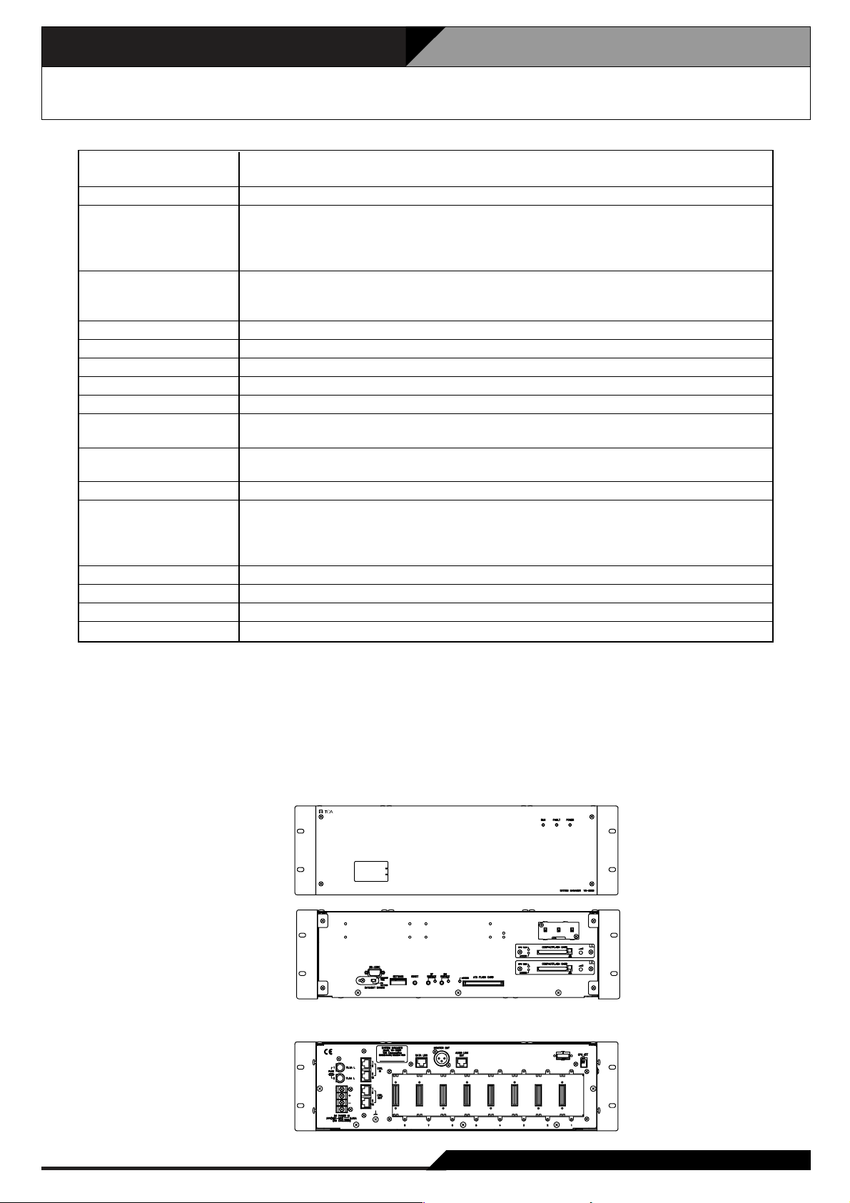
4.4. System Manager VX-2000
Power Source 24V DC (operating range: 20 – 40V DC)
M3.5 screw terminal, distance between barriers: 8.8m
Current consumption Under 650mA (20V DC)
Input –20dB*, unbalanced, Number of module slots: 8
Usable module: VX-200XR, VX-200XI, 900 series plug-in modules (M-01F,
M-01M, M-01P, M-01S, M-03P, M-51F, M-51S, M-61F, M-61S, M-61T, U-01F,
U-01P, U-01R, U-01S, U-01T, M-03R, U-03S, U-61S, U-61T)
Audio Link Output Number of audio buses: 4
0dB*, electronically balanced, RJ45 female connector
Twisted-pair straight cable (TIA/EIA-568A standard)
Monitor Output 0dB*, electronically balanced, XLR receptacle (3 pins)
Frequency Response 20 – 20,000Hz
S/N Ratio Over 60dB
Distortion Under 0.5%
Cross Talk Under –60dB (1kHz, 0dB*)
Control Input 16 inputs, no-voltage make contact, open voltage: 17V DC,
Short circuit current: Under 5mA, RJ45 connector x 2
Control Output 16 outputs, open collector output, withstand voltage: 30V DC,
Control current: Under 5mA, RJ45 connector x 2
Chime Tone Built-in chime: 4-tone chime (up)/4-tone chime (down)/2-tone chime/Gong
Communication System PC (Setting software to be installed): D-sub connector (9 pins), cross cable,
RS-232C
VX-2000SF: RJ45 female connector,
Twisted-pair straight cable (TIA/EIA-568A standard), LONWORKS RS-485
Operating Temperature 0˚ C to +40˚ C
Finish Panel: Surface-treated steel plate, black, 30% gloss, paint
Dimensions 482 (W) x 132.6 (H) x 337 (D)mm
Weight 6.4kg
* 0 dB = 1 V
• Accessories
Rack mounting bracket (preinstalled on the unit) x 2, Rack mounting screw x 4, Fiber washer x 4,
Blank panel x 7, Blank panel mounting screw x 14, Setting software installation CD x 1,
Fuse (T1.6A L) x 1/(T6.3A L) x 1
• Optional products
Voice announcement board: EV-200, Isolation transformer: IT-450 (audio link output)
[Front]
[Front section without front panel]
[Rear]
Page 13
4-5
4. Specifications
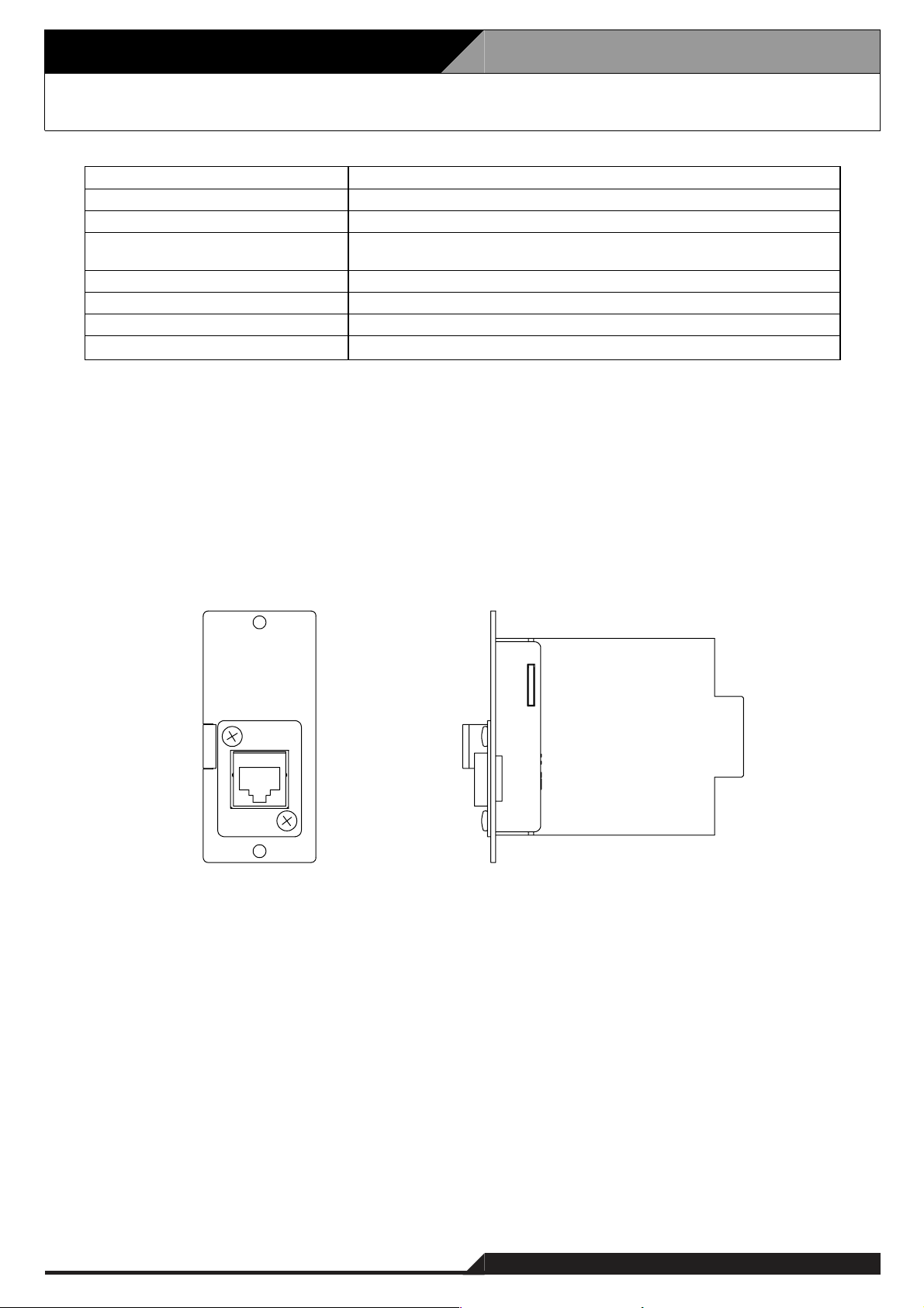
4.5. Remote Microphone Input Module VX-200XR
Supplied from VX-2000
Under 15 mA
RM-200X and RM-200XF
RJ45 female connector
Twisted-pair straight cable (TIA/EIA-568A standard)
Panel: Alumite finished aluminum, white
35 (W) x 78 (H) x 88 (D) mm
70 g
VX-2000
Power Source
Current Consumption
Connectable Remote Microphone
Input Connector
Finish
Dimensions
Weight
Applicable Model
• Accessory
Mounting screw .......................................... 2
[Front] [Side]
Page 14
4. Specifications
4-6
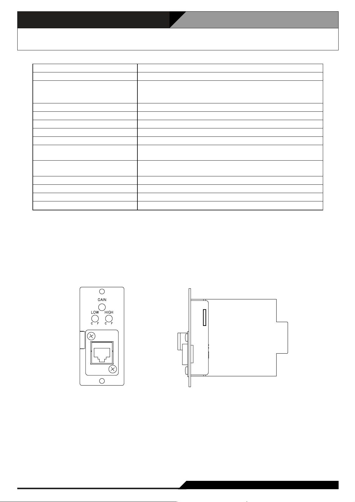
4.6. Audio Input Module with Control input VX-200XI
Supplied from VX-2000
Under 30 mA
MIC: –70 to – 42.5dB* (adjustable)
LINE: –20 to +7.5dB* (adjustable)
MIC or LINE selectable by the built-in switch
9 to 15 dB attenuation (adjustable)
8 to 14 dB attenuation (adjustable)
Under 0.5%
50 – 20,000 Hz
15V (open), 6V (current consumption: 3.3mA)
No-voltage make contact, open voltage: 17V DC,
short-circuit current: Under 5mA
RJ45 female connector
Twisted-pair straight cable (TIA/EIA-568A standard)
Panel: Alumite finished aluminum, white
35 (W) x 78 (H) x 88 (D) mm
70 g
VX-2000
*0 dB = 1 V
Power Source
Current Consumption
Input Sensitivity
(Rated Output –20dB)
Low Cut Filter (100 Hz)
High Cut Filter (10 kHz)
Distortion
Frequency Response
Phantom Power
Control Input
Input Connector
Finish
Dimensions
Weight
Applicable Model
• Accessory
Mounting screw............................................2
• Optional products
Isolation transformer: IT-450
[Front] [Side]
Page 15
4-7
4. Specifications
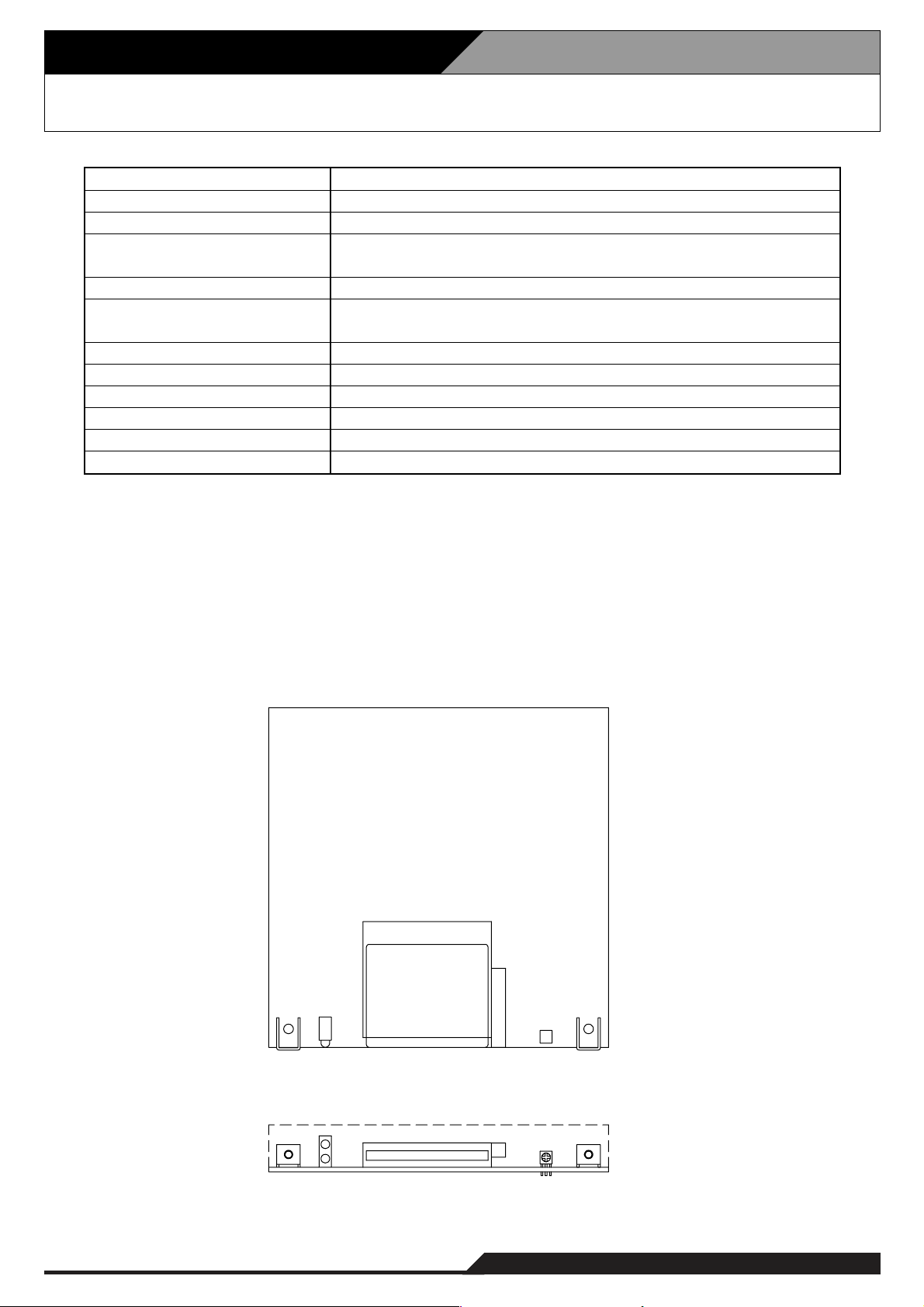
4.7. Voice Announcement Board EV-200
*10 dB = 1 V
*
2
Trademark of SanDisk Corporation.
Note: Use the CompactFlash card adapter on the market for recording by the EV-350R.
• Accessory
Mounting screw .......................................... 2
24 V DC, 0.2 A
5 W
0 dB*
1
20 – 20,000 Hz (44.1 kHz sampling)
20 – 14,000 Hz (32 kHz sampling)
Under 0.3% (44.1 kHz, recording method: Extremely High)
SanDisk*
2
CompactFlash*2card is optionally required.
Number of mountable card: 1
Single source playback
8 programs
0°C to +50°C
Under than 90% RH (must be free from dew condensation)
120 (W) x 18.6 (H) x 121 (D) mm
110 g
Power Source
Power Consumption
Output
Frequency Response
Distortion
Memory Card
Playback Mode
No. of Playback Program
Operating Temperature
Operating Humidity
Dimensions
Weight
[Top]
[Front]
Page 16
4. Specifications
4-8
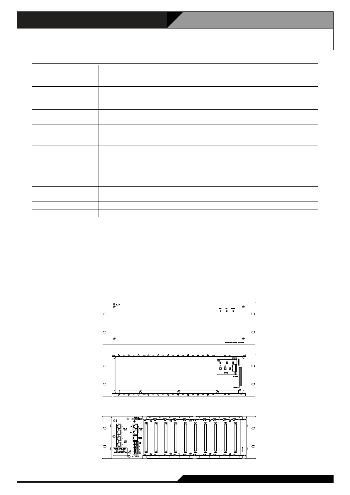
4.8. Surveillance Frame VX-2000SF
Power Source 24 V DC (operating range: 20 – 40 V DC)
M3.5 screw terminal, distance between barriers: 8.8m
Current consumption Under 2 A (40 V DC)
Number of Module Slot 10, usable modules: VX-200SZ, VX-200SP, VX-200SI, VX-200SO
Frequency Response 20 – 20,000Hz
S/N Ratio Over 60dB
Distortion Under 0.5%
Cross Talk Under –60dB (1kHz, 0dB*)
Audio Link Input/Output Number of audio busses: 4
0dB*, electronically balanced, RJ45 female connector
Twisted-pair straight cable (TIA/EIA-568A standard)
Standby Amplifier Link RJ45 female connector for connecting the VP-2064, VP-2122, VP-2241, VP-2421
Power Amplifier.
Twisted-pair straight cable (TIA/EIA-586A standard)
Communication System VX-2000, VX-2000SF: RJ45 female connector x 2, LONWORKS RS-485
VX-2000DS: RJ45 female connector x 2,
Twisted-pair straight cable (TIA/EIA-586A standard)
Operating Temperature 0˚ C to +40˚ C
Finish Panel: Surface-treated steel plate, black, 30% gloss, paint
Dimensions 482 (W) x 132.6 (H) x 337 (D)mm
Weight 5.6 kg
* 0 dB = 1 V
Note: LONWORKS is a trademark of Echelon Corporation.
• Accessories
Rack mounting bracket (preinstalled on the unit) x 2, Rack mounting screw x 4, Fiber washer x 4,
Blank panel x 9, Blank panel mounting screw x 18, Standby amp. cable (3m) x 1
• Optional products
Isolation transformer: IT-450 (audio link output)
[Front]
[Front section without front panel]
[Rear]
Page 17
4-9
4. Specifications
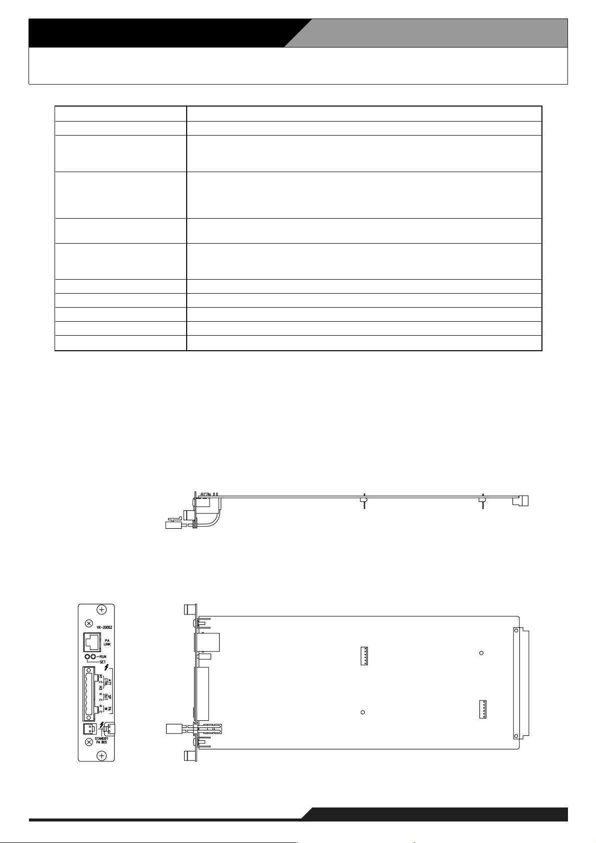
4.9. Impedance Detection Module VX-200SZ
• Optional product
Equaliser card: VX-200SE
• Accessory
Plug-in screw terminal ................................ 1
Power Source
Current Consumption
Power Amplifier Link
External Attenuator Control
Output
Speaker Output
Power Amplifier Input
Fault Detection System
Finish
Dimensions
Weight
Applicable Model
Supplied from VX-2000SF
Under 150mA
RJ45 female connector for connecting the VP-2064, VP-2122,
VP-2241, VP-2421 Power Amplifier.
Twisted-pair straight cable (TIA/EIA-568A standard)
Plug-in screw connector, relay, no-voltage make contact output, transfer type,
withstand voltage: 30V DC, 250V AC, contact current: Under 7A (DC),
under 7A (AC)
Applicable cable diameter: AWG24 – AWG 22
Plug-in screw connector
Applicable cable diameter: AWG24 – AWG 22
Plug-in screw connector for connecting the VP-2064, VP-2122, VP-2241,
VP-2421 Power Amplifier.
Applicable cable diameter: AWG24 – AWG 22
Short circuit, open circuit (impedance detection method), ground fault
Panel: Surface-treated steel plate
30.5 (W) x 132.6 (H) x 290.3 (D)mm
320g
VX-2000SF
[Top]
[Side][Front]
Page 18
4. Specifications
4-10
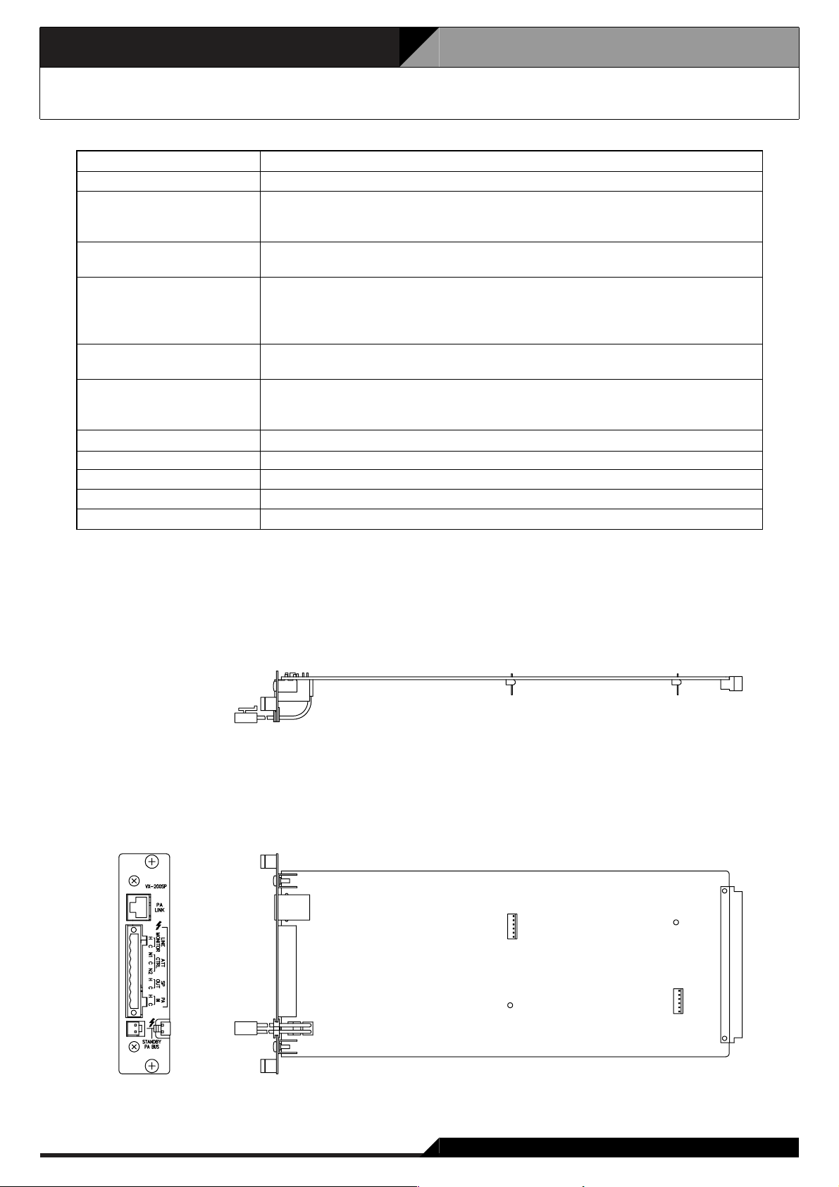
4.10 Pilot Tone Detection Module VX-200SP
• Optional product
Equaliser card: VX-200SE
• Accessory
Plug-in screw terminal ................................ 1
Power Source
Current Consumption
Power Amplifier Link
Line Monitor
External Attenuator Control
Output
Speaker Output
Power Amplifier Input
Fault Detection System
Finish
Dimensions
Weight
Applicable Model
Supplied from VX-2000SF
Under 100mA
RJ45 female connector for connecting the VP-2064, VP-2122, VP-2241,
VP-2421 Power Amplifier.
Twisted-pair straight cable (TIA/EIA-568A standard)
Plug-in screw connector
Applicable cable diameter: AWG24 – AWG 22
Plug-in screw connector, relay, no-voltage make contact output, transfer type,
withstand voltage: 30V DC, 250V AC, contact current: Under 7A (DC),
under 7A (AC)
Applicable cable diameter: AWG24 – AWG 22
Plug-in screw connector
Applicable cable diameter: AWG24 – AWG 22
Plug-in screw connector for connecting the VP-2064, VP-2122,
VP-2241, VP-2421 Power Amplifier.
Applicable cable diameter: AWG24 – AWG 22
Short circuit, open circuit (pilot tone detection method), ground fault
Panel: Surface-treated steel plate
30.5 (W) x 132.6 (H) x 290.3 (D)mm
240g
VX-2000SF
[Top]
[Side]
[Front]
Page 19
4-11
4. Specifications
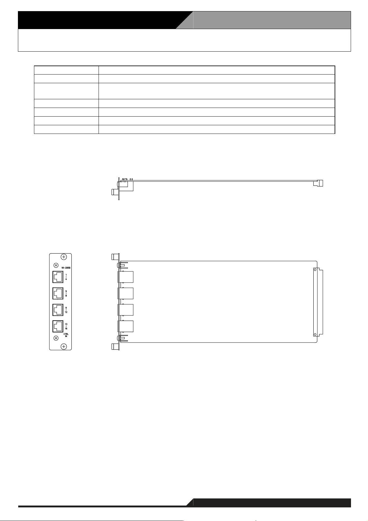
4.11. Control Input Module VX-200SI
Supplied from VX-2000SF
Under 100 mA
16
inputs, no-voltage make contact, open voltage: 24V DC,
short circuit current: under 10mA, RJ45 connector
Panel: Surface-treated steel plate
30.5 (W) x 132.6 (H) x 290.3 (D) mm
200 g
VX-2000SF
Power Source
Current Consumption
Control Input
Finish
Dimensions
Weight
Applicable Model
[Top]
[Side][Front]
Page 20
4. Specifications
4-12
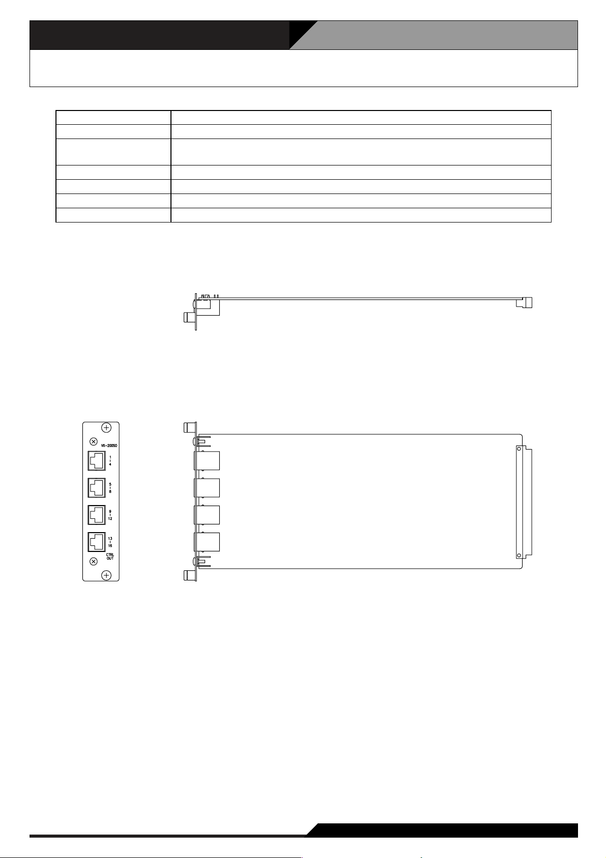
4.12. Control Output Module VX-200SO
Supplied from VX-2000SF
Under 150 mA
16
outputs, no-voltage make contact, contact capacity: 28V DC, 1A,
RJ45 connector
Panel: Surface-treated steel plate
30.5 (W) x 132.6 (H) x 290.3 (D) mm
250 g
VX-2000SF
Power Source
Current Consumption
Control Output
Finish
Dimensions
Weight
Applicable Model
[Top]
[Side][Front]
Page 21
4-13
4. Specifications
4.13. Equaliser Card VX-200SE
Supplied from VX-200SZ, VX-200SP
Under 50 mA
80 Hz, 125 Hz, 250 Hz, 500 HZ, 1 kHz, 2 kHz, 4 kHz, 8 kHz, 12 kHz
±12 dB, adjustable in 2 dB steps
110 (W) x 90 (H) x 21.4 (D) mm
50 g
VX-200SZ, VX-200SP
Power Source
Current Consumption
Equaliser Centre Frequency
Gain Range
Dimensions
Weight
Applicable Model
[Top]
[Side]
Page 22
4. Specifications
4-14
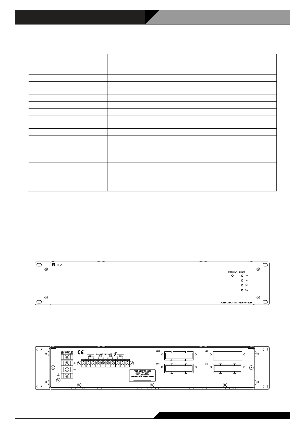
4.14. Power Amplifier 4 x 60 W VP-2064
• Accessories
Rack mounting screw 4
Fiber washer ...............................................
.................................
4
Power Source
Current Consumption (EN60065)
Rated Output Power
Output Voltage/Impedance
Number of Channels
Input
Number of Module Slots
Output
Frequency Response
Distortion
S/N Ratio
Panel Indicator
Operating temperature
Finish
Dimensions
Weight
28 V DC (operating range: 20 – 40 V DC)
M4 screw terminal, distance between barriers: 12mm
4.8 A in total
60 W x 4
100V/167Ω, 70V/83Ω, 50V/41Ω
(selectable by the internal wiring change)
4
Specified by input module VP-200VX
4, usable module: VP-200VX
Power amplifier output (speaker line): M3.5 screw terminal,
distance between barriers: 8.8mm
40 – 16,000 Hz, ±3 dB (at 1/3 rated output)
Under 1% (at rated output, 1 kHz)
Over 80 dB
Channel power indicator: 4 channels, dual colour LED
Overheat indicator: Yellow LED
0°C to +40°C
Panel: Surface-treated steel plate, black, 30% gloss, paint
482 (W) x 88.4 (H) x 340.5 (D) mm
11.2 kg
[Front]
[Rear]
Page 23
4-15
4. Specifications
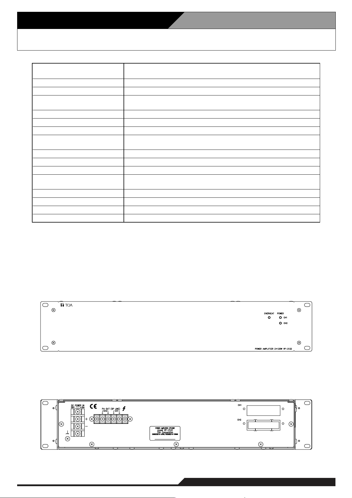
4.15. Power Amplifier 2 x 120 W VP-2122
Power Source
Current Consumption (EN60065)
Rated Output Power
Output Voltage/Impedance
Number of Channels
Input
Number of Module Slots
Output
Frequency Response
Distortion
S/N Ratio
Panel Indicator
Operating temperature
Finish
Dimensions
Weight
28 V DC (operating range: 20 – 40 V DC)
M4 screw terminal, distance between barriers: 12mm
4.8 A in total
120 W x 2
100V/83Ω, 70V/41Ω, 50V/21Ω
(selectable by the internal wiring change)
2
Specified by input module VP-200VX
2, usable module: VP-200VX
Power amplifier output (speaker line): M3.5 screw terminal,
distance between barriers: 8.8mm
40 – 16,000 Hz, ±3 dB (at 1/3 rated output)
Under 1% (at rated output, 1 kHz)
Over 80 dB
Channel power indicator: 2 channels, dual colour LED
Overheat indicator: Yellow LED
0°C to +40°C
Panel: Surface-treated steel plate, black, 30% gloss, paint
482 (W) x 88.4 (H) x 340.5 (D) mm
9.1 kg
• Accessories
Rack mounting screw 4
Fiber washer ...............................................
.................................
[Front]
[Rear]
4
Page 24
4. Specifications
4-16
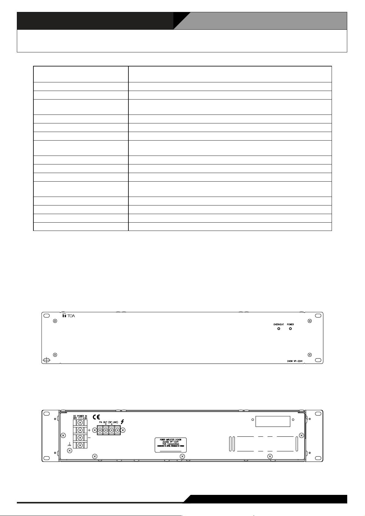
4.16. Power Amplifier 1 x 240 W VP-2241
Power Source
Current Consumption (EN60065)
Rated Output Power
Output Voltage/Impedance
Number of Channels
Input
Number of Module Slots
Output
Frequency Response
Distortion
S/N Ratio
Panel Indicator
Operating temperature
Finish
Dimensions
Weight
28 V DC (operating range: 20 – 40 V DC)
M4 screw terminal, distance between barriers: 12mm
4.8 A
240 W
100V/41Ω, 70V/21Ω, 50V/10Ω
(selectable by the internal wiring change)
1
Specified by input module VP-200VX
1, usable module: VP-200VX
Power amplifier output (speaker line): M3.5 screw terminal,
distance between barriers: 8.8mm
40 – 16,000 Hz, ±3 dB (at 1/3 rated output)
Under 1% (at rated output, 1 kHz)
Over 80 dB
Channel power indicator: 1 channels, dual colour LED
Overheat indicator: Yellow LED
0°C to +40°C
Panel: Surface-treated steel plate, black, 30% gloss, paint
482 (W) x 88.4 (H) x 340.5 (D) mm
8.1 kg
• Accessories
Rack mounting screw 4
Fiber washer ...............................................
.................................
[Front]
[Rear]
4
Page 25

4-17
4. Specifications
4.17. Power Amplifier 1 x 420 W VP-2421
Power Source
Current Consumption (EN60065)
Rated Output Power
Output Voltage/Impedance
Number of Channels
Input
Number of Module Slots
Output
Frequency Response
Distortion
S/N Ratio
Panel Indicator
Operating temperature
Finish
Dimensions
Weight
28 V DC (operating range: 20 – 40 V DC)
M4 screw terminal, distance between barriers: 12mm
7.6 A
420 W
100V/24Ω, 70V/12Ω, 50V/6Ω
(selectable by the internal wiring change)
1
Specified by input module VP-200VX
1, usable module: VP-200VX
Power amplifier output (speaker line): M3.5 screw terminal,
distance between barriers: 8.8mm
40 – 16,000 Hz, ±3 dB (at 1/3 rated output)
Under 1% (at rated output, 1 kHz)
Over 80 dB
Channel power indicator: 1 channels, dual colour LED
Overheat indicator: Yellow LED
0°C to +40°C
Panel: Surface-treated steel plate, black, 30% gloss, paint
482 (W) x 88.4 (H) x 340.5 (D) mm
9.5 kg
• Accessories
Rack mounting screw 4
Fiber washer ...............................................
.................................
[Front]
[Rear]
4
Page 26
4. Specifications
4-18
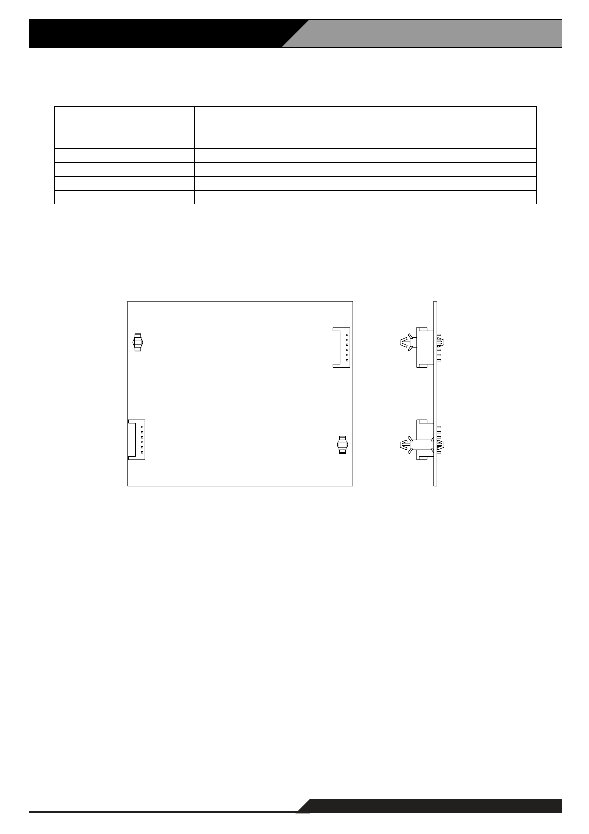
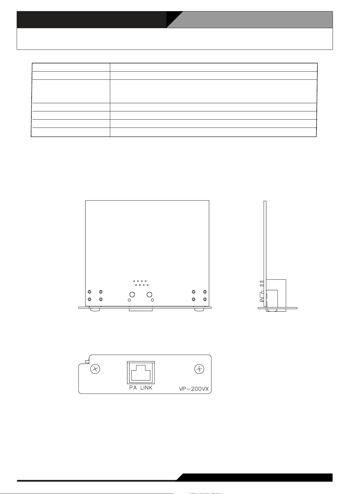
4.18. Power Amplifier Input Module VP-200VX
Supplied from VP-2064, VP-2122, VP-2241, or VP-2421
Under 30 mA
RJ45 female connector for connecting the VX-200SP or
VX-200SZ Audio Output module.
Twisted-pair straight cable (TIA/EIA-568A standard)
Panel: Surface treated steel plate
88 (W) x 25.8 (H) x 53.2 (D) mm
50 g
VP-2064, VP-2122, VP-2241, VP-2421
Power Source
Current Consumption
Power Amplifier Link
Finish
Dimensions
Weight
Applicable Model
[Top] [Side]
[Front]
Page 27
4-19
4. Specifications
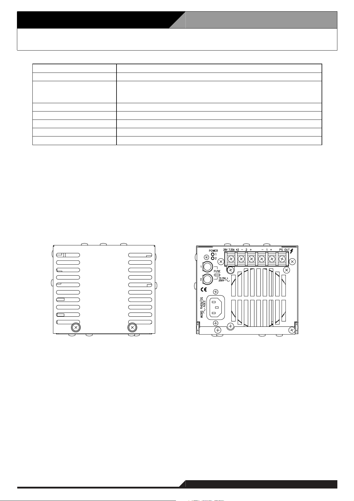
4.19. Power Supply Unit VX-200PS
230 V AC, 50/60 Hz
0°C to +40°C
VX-2000PF
Surface-treated steel plate
135 (W) x 118.2 (H) x 333.8 (D) mm
13.2 kg
Power Source
Operating Temperature
Applicable Frame
Finish
Dimensions
Weight
• Accessories
Fuse (T3.15 A L) ......................................... 1
Power cable ................................................ 1
PS OUT
580 W Power Consumption
Rated output: 210 W (29V , 7.25 A) x 2
Peak output: 400 W x 2
M4 screw terminal, distance between barriers: 11 mm
[Front] [Rear]
Page 28
4. Specifications
4-20
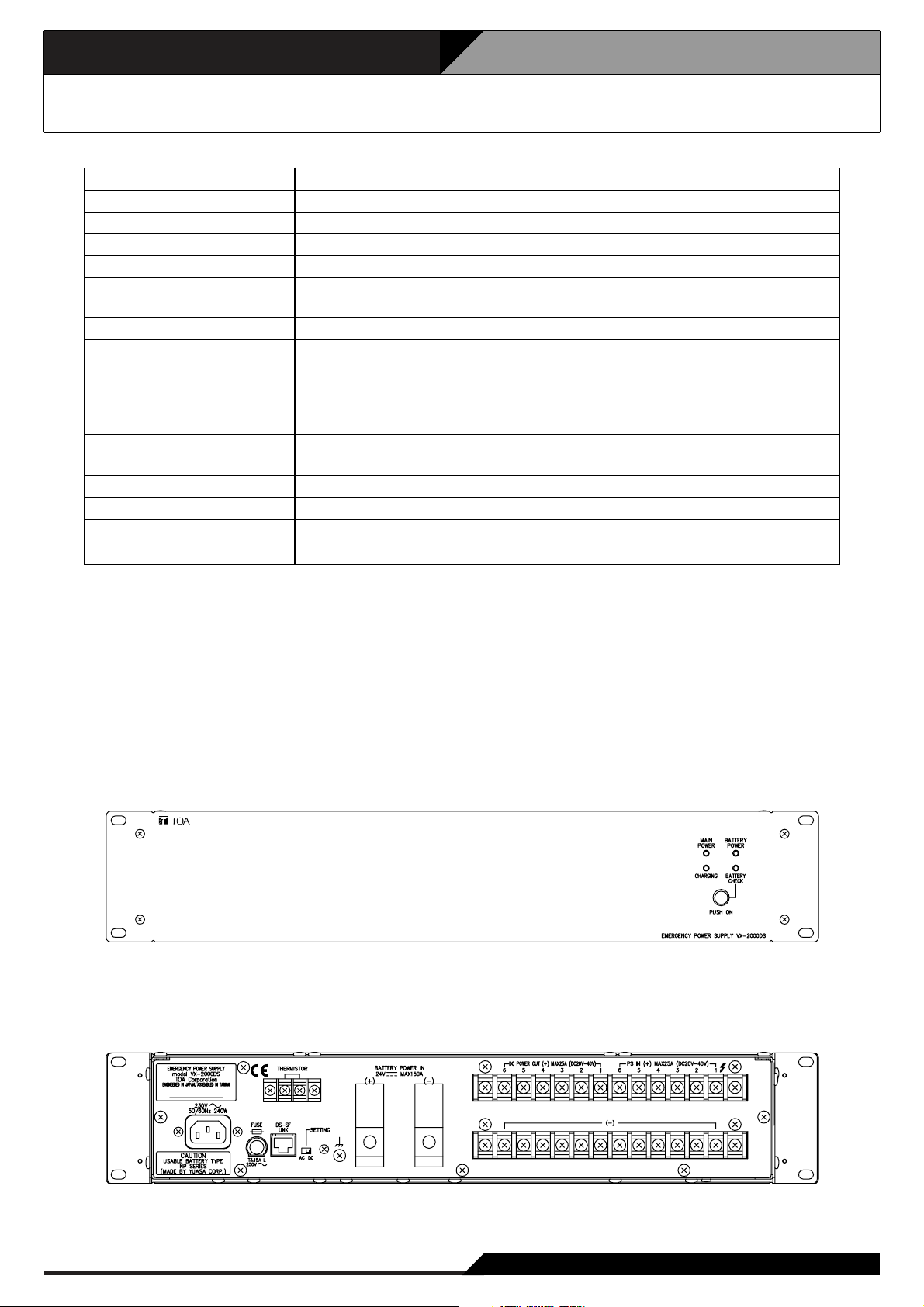
4.20. Emergeny Power Supply VX-2000DS
230 V AC, 50/60 Hz
240 W maximum
YUASA NP Series (12 V x 2 or 4)
Trickle charging
5 A maximum
27.3 V ±0.3 V (at 25°C)
Temperature correction coefficient: –40 mV/°C
6 M4 screw terminal, distance between barriers: 11mm
6 (25 A max. each) M4 screw terminal, distance between barriers: 11mm
RJ45 female connector for connecting the VX-2000SF Surveillance Frame.
Twisted-pair straight cable (TIA/EIA-568A standard)
Type of control signal: Battery check, AC power status, DC power status,
charging circuit failure, and battery failure
1 pair of positive and negative terminals
Applicable cable diameter: AWG 6 – AWG 1/0
0°C to +40°C
Panel: Surface-treated steel plate, black, 30% gloss, paint
482 (W) x 88.4 (h) x 377.6 (D) mm
10.5 kg
Power Source
Power Consumption
Applicable Battery
Charging Method
Charging Current
Charging Output Voltage
Power Supply Input
DC Power Output
Control Connector
Battery Connection
Operating Temperature
Finish
Dimensions
Weight
• Accessories
Rack mounting screw .................................. 4
Fiber washer .............................................. 4
Blade fuse (40 A) ........................................ 3
Fuse (T3.15 A L) 1
Power cable 1
.........................................
................................................
[Front]
[Rear]
Page 29
4-21
4. Specifications
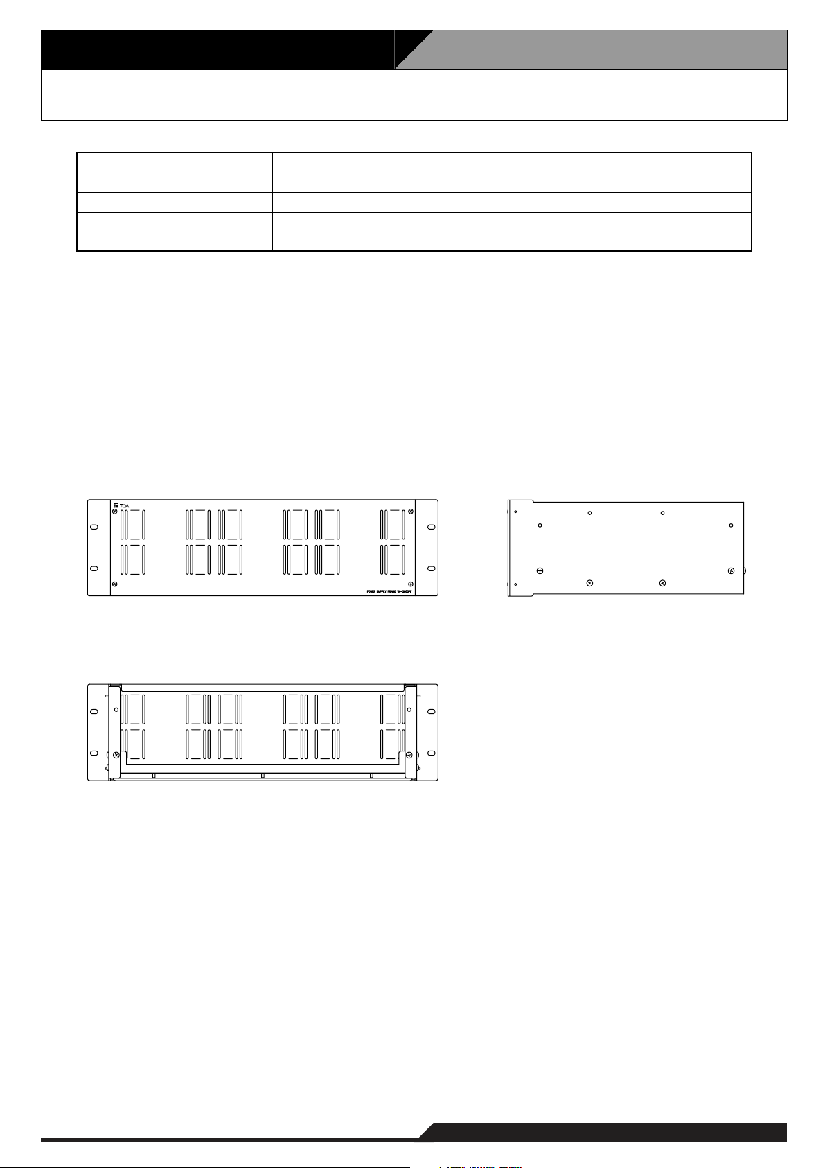
4.21. Power Supply Frame VX-2000PF
Panel: Surface-treated steel plate, black, 30% gloss, paint
483 (W) x 132.6 (H) x 324.8 (D) mm
5.5 kg
Finish
Dimensions
Weight
Side panel x 2, Chassis x 1, Front panel x 1
VX-200PS (up to 3)
Product Composition
Usable Unit
• Accessories
Rack mounting screw ................................. 4
Fiber washer .............................................. 4
[Front] [Side]
[Rear]
Page 30

5. Typical System Examples 5.1. Typical System Outline
5.1.1. External View of the Building
Here, system installations, settings, connections and operations are explained, taking some typical systems
as an example.
The building shown below is used as an example.
The location is a hotel where Building A is linked with Building B. Building A was built earlier, and Building B
added later. The original public address system was expanded by adding a VX-2000SF to cover Building B.
Building B Building A
5-1
Page 31

5. Typical System Examples 5.1. Typical System Outline
5.1.2. Internal Wiring
Speaker arrangements and their wiring in Buildings A and B are as shown in the figure below.
Building A
Corridor6F
StairsStaff area
Conference room1F
Guest rooms
6F
Corridor5F
Guest rooms5F
Corridor4F
Guest rooms4F
Corridor3F
Guest rooms3F
Corridor2F
Guest rooms2F
Hallway1F
Security
room
Staff area
VX-2000
VX-2000SF
Amp.
StairsStaff area
VX-2000SF
Amp.
VM
Amp.
RestaurantBar
Building B
Conference room
1F
LobbyGF
Fireman's
Microphone
LobbyGF
Reception
Corridor3F
Guest rooms
3F
Corridor2F
Guest rooms2F
Hallway1F
Entrance
Staff areaGF
5-2
Page 32

5. Typical System Examples 5.1. Typical System Outline
5.1.3. Block Diagram
The system's block diagram is shown below.
Note: Guest rooms 1 and 2 represent dual speaker lines of an interleaved speaker system provided for each
guest room as fail safe system.
Building A
RM-200XF
A-GF Lobby
RM-200X + RM-210 x 4
A-GF Reception
VX-2000 VX-2000SF A1
VX-200XR
VX-200XR
VX-200SZ VP-200VX
VX-200SZ
VX-200SZ
VX-200SZ
VP-2064
VP-200VX
VP-200VX
VP-200VX
A-6F Guest room 1
A-6F Guest room 2
A-5F Guest room 1
A-5F Guest room 2
A-GF Security room
A-GF Security room
A-GF Security room
A-GF Security room
A-1F
Conference room
Wireless Tuner
Sensor
RM-200X + RM-210 x 7
Tel Device
BGM Player 1
BGM Player 2
Pre-Amplifier
Push to use the
Conference room.
Fire Alarm
Parking gate
control, etc.
VX-200XR
VX-200XI
U-01R
U-01R
U-01R
EV-200
Chime
Control Input
Control Output
VX-200SZ VP-200VX
VX-200SZ
VX-200SZ
VX-200SZ
VX-200SZ VP-200VX
VX-200SZ
VP-200VX
VP-200VX
VP-200VX
VP-200VX
VP-200VX
VX-2000SF A2
VX-200SZ VP-200VX
VX-200SZ
VX-200SZ
VX-200SZ VP-200VX
VX-200SZ VP-200VX
VX-200SZ VP-200VX
VP-200VX
VP-200VX
VP-2064
VP-2064
VP-2064
VP-2241
VP-2122
A-4F Guest room 1
A-4F Guest room 2
A-3F Guest room 1
A-3F Guest room 2
A-2F Guest room 1
A-2F Guest room 2
Standby Amplifier
A-1F Hallway
A-GF Lobby
A-GF Restaurant
A-1F
Conference room
A-GF Bar
A-GF, 1 – 5F
Staff area
VX-200SZ VP-200VX
To the next page To the next page
VP-2122
VP-2122
VP-200VX
A-Stairs / corridor
Standby Amplifier
5-3
Page 33

5. Typical System Examples 5.1. Typical System Outline
5.1.3. Block Diagram
Continued from the previous page Continued from the previous page
Building B
VX-2000SF B
Sensor
VX-200SZ
VX-200SZ
VX-200SZ
VX-200SZ
VP-2064
VP-200VX
VP-200VX
VP-200VX
VP-200VX
B-3F Guest room 1
B-3F Guest room 2
B-2F Guest room 1
B-2F Guest room 2
VX-200SZ
VX-200SZ
VX-200SZ
VX-200SZ
VX-200SP
VP-2064
VP-200VX
VP-200VX
VP-2122
VP-200VX
VP-200VX
VP-2241
VP-200VX
VM-2240
Wireless Tuner
B-1F Hallway
B-GF Lobby
B-GF, 1 – 5F
Staff area
B-Stairs / corridor
B-1F
Conference room
VP-2241
VP-200VX
Standby Amplifier
5-4
Page 34

5. Typical System Examples 5.1. Typical System Outline
5.1.4. Equipment Rack Conceptual Drawing
Shown below are conceptual drawings for component racks installed in Buildings A and B.
Building A
[Rack A-1] [Rack A-2]
CR-273 CR-273
60W-4CH POWER AMPLIFIER PANEL VP-2064
60W-4CH POWER AMPLIFIER PANEL VP-2064
MAIN
POWER
POWER SUPPLY CONTROL PANEL DS-2000
1
POWEROVERHEAT
CH1
CH2
CH3
CH4
POWEROVERHEAT
CH1
CH2
CH3
CH4
2
3
4
5
6
PF-013B
VP-2064
VP-2064
PF-013B
7
8
VX-2000SF
9
10
11
VX-2000
12
13
BGM1
14
15
240W-1CH POWER AMPLIFIER PANEL VP-2241
240W-1CH POWER AMPLIFIER PANEL VP-2241
120W-2CH POWER AMPLIFIER PANEL VP-2122
120W-2CH POWER AMPLIFIER PANEL VP-2122
60W-4CH POWER AMPLIFIER PANEL VP-2064
60W-4CH POWER AMPLIFIER PANEL VP-2064
POWEROVERHEAT
CH1
POWEROVERHEAT
CH1
POWEROVERHEAT
CH1
CH2
POWEROVERHEAT
CH1
CH2
POWEROVERHEAT
CH1
CH2
CH3
CH4
POWEROVERHEAT
CH1
CH2
CH3
CH4
16
17
BGM2
18
19
20
VX-2000PF
21
22
23
24
25
26
27
PF-013B
VX-2000DS
PF-013B
PF-023B
MAIN
POWER
PUSH ON
POWER SUPPLY CONTROL PANEL DS-2000
BATTERY
POWER
BATTERYCHARGING
CHECK
BATTERY
POWER
BATTERYCHARGING
CHECK
PUSH ON
1
2
3
4
5
6
7
8
9
10
11
12
13
14
15
16
17
18
19
20
21
22
23
24
25
26
27
PF-013B
VP-2241
VP-2241
VP-2122
PF-013B
VP-2122
VP-2064
VP-2064
PF-013B
VX-2000SF
VX-2000PF
PF-013B
VX-2000DS
PF-013B
PF-023B
Building B
[Rack B]
CR-273
240W-1CH POWER AMPLIFIER PANEL VP-2241
240W-1CH POWER AMPLIFIER PANEL VP-2241
120W-2CH POWER AMPLIFIER PANEL VP-2122
60W-4CH POWER AMPLIFIER PANEL VP-2064
60W-4CH POWER AMPLIFIER PANEL VP-2064
MAIN
POWER
POWER SUPPLY CONTROL PANEL DS-2000
1
POWEROVERHEAT
CH1
POWEROVERHEAT
CH1
POWEROVERHEAT
CH1
CH2
POWEROVERHEAT
CH1
CH2
CH3
CH4
POWEROVERHEAT
CH1
CH2
CH3
CH4
2
3
4
5
6
7
8
9
10
11
12
13
PF-013B
VP-2241
VP-2241
VP-2122
PF-013B
VP-2064
VP-2064
PF-013B
14
15
VX-2000SF
16
17
PF-023B
18
19
20
VX-2000PF
21
22
BATTERY
POWER
BATTERYCHARGING
CHECK
PUSH ON
23
24
25
26
27
PF-013B
VX-2000DS
PF-013B
PF-023B
5-5
Page 35

5-6
5. Typical System Examples
5.2. Equipment Interconnection Examples
5.2.1. VX-2000 Connections to Remote Microphones and Input Source Equipment
[RM-200XF Bottom]
AC230 V
50/60 Hz
Cat. 5 STP
[RM-200X Rear]
DC POWER IN
24V
LINK
MICSP
MIC IN
Cat. 5 STP Cat. 5 STP
PM-660U
CD Player
Monitor Speaker and Zone selector
Cat. 5 STP
LINK
Base Pattern change and
Failure Output Receipt switches
Failure Output indicators
[VX-2000 Rear]
RJ45 male connector
RCA plug
XLR type
female connector
From VX-2000DS'
DC POWER OUT
DC POWER IN
CTRL
IN
CTRL
OUT
Power
Amplifier
MONITOR OUT
RM LINK RM LINK
VX-200XIU-03R
VX-200XR
Page 36

5. Typical System Examples
5.2. Equipment Interconnection Examples
5-7
5.2.2. Connections between VX-2000 and VX-2000SF
[VX-2000 Rear]
RJ45 male connector
From VX-2000DS'
DC POWER OUT
Cat. 5 STP
[VX-2000SF Rear]
AUDIO
LINK
DATA
LINK
OUT
IN
DATA LINK
AUDIO LINK
OUT
Cat. 5 STP
From VX-2000DS'
DC POWER OUT
Cat. 5 STP
Cat. 5 STP
From VX-2000DS'
DC POWER OUT
DC POWER IN
[VX-2000SF Rear]
AUDIO
LINK
DATA
LINK
DC POWER IN
Cat. 5 STP
OUT
IN
Cat. 5 STP
Next VX-2000SF
Next VX-2000SF
Page 37

5-8
5. Typical System Examples
5.2. Equipment Interconnection Examples
5.2.3. SF Modules (VX-200SP, VX-200SZ, VX-200SI, VX-200SO) Connections
[SF Modules Configuration Example]
[VX-200SP and VX-200SZ Connection to Power Amplifier and Speakers]
VX-200SZ VX-200SP
[VX-2000SF Rear]
From VX-2000DS'
DC POWER OUT
VX-200SZ
Cat. 5 STP
PA LINK
VX-200SI
VX-200SO
RJ45 male connector
From VX-2000DS'
DC POWER OUT
SP OUT
PA IN
[VP-2122 Rear]
VX-200SP
PA LINK
LINE MONITOR
SP OUT
PA IN
H
C
H
C
1
n
VP-200VX
VP-200VX
Cat. 5 STP
H
C
H
C
H
C
1n
Page 38

5. Typical System Examples
5.2.3. SF Modules (VX-200SP, VX-200SZ, VX-200SI, VX-200SO) Connections
[VX-200SP Connection to External Attenuator]
• 3-wire System Connection
VX-200SP
5.2. Equipment Interconnection Examples
End of line
LINE MONITOR
ATT CTRL
SP OUT
H
C
(NO)
N1
C
N2
(NC)
H
C
• 4-wire System Connection
VX-200SP
LINE MONITOR
ATT CTRL
SP OUT
H
C
N1
(NO)
C
N2
(NC)
H
C
DC Power
Supply
AT-603 etc.
(–)(+)
SPNR
End of line
Relay
Control
(+)(–)
SPN
[VX-200SZ Connection to External Attenuator]
Note: Only the external attenuators of 4-wire system can be used for the VX-200SZ.
VX-200SZ
DC Power
Supply
(–)(+)
(NO)
N1
SP OUT
C
N2
(NC)
H
C
Relay
Control
(+)(–)
SPN
ATT CTRL
5-9
Page 39

5. Typical System Examples
5.2.3. SF Modules (VX-200SP, VX-200SZ, VX-200SI, VX-200SO) Connections
[VX-200SI and VX-200SO Connection to External Devices]
5.2. Equipment Interconnection Examples
INPUT 1
COM 1
INPUT 2
COM 2
INPUT 16
COM 16
VX-200SI
OUTPUT 1
COM 1
OUTPUT 2
COM 2
OUTPUT 16
COM 16
VX-200SO
5-10
Page 40

5. Typical System Examples
5.2. Equipment Interconnection Examples
5-11
5.2.4. Connections Between VX-2000SF and Standby Amplifier
[VP-2241 Rear]
From VX-2000DS'
DC POWER OUT
VP-200VX
Cat. 5 STP
From VX-2000DS'
DC POWER OUT
[VX-2000SF Rear]
RJ45 male connector
VX-200SI
VX-200SZ
Be sure to connect between all STANDBY PA BUS
connectors as shown above.
VX-200SP
VX-200SO
Page 41

5-12
5. Typical System Examples
5.2. Equipment Interconnection Examples
5.2.5. Connections Between VX-2000SF and VX-2000DS
[VX-2000SF Rear]
[VX-2000DS No.1 Rear]
Cat. 5 STP
[VX-2000DS No.2 Rear]
Cat. 5 STP
RJ45 male connector
Page 42

5. Typical System Examples
5.2. Equipment Interconnection Examples
5-13
5.2.6. Connections Between VX-2000DS and VX-2000PS
VX-200PS Rear VX-200PS Rear VX-200PS Rear
VX-2000PF
AC230 V
50/60 Hz
PS OUT
––
+
+
AC230 V
50/60 Hz
––
PS OUT
To DC (+) inputs of the following units.
VX-2000/-2000SF, VP-2064/-2122/-2241/-2421
[VX-2000DS Rear]
––
+
+
PS OUT
+
+
AC230 V
50/60 Hz
AC230 V
50/60 Hz
Cat. 5 STP
To VX-2000SF
DS–SF LINK 1, 2 connectors
Lead-acid
Battery
Caution
The charging current from VX-2000DS is 5 A maximum.
Applicable Batteries: YUASA NP Series (12 V x 2)
Lead-acid
Battery
To DC (–) inputs of the following units.
VX-2000/-2000SF, VP-2064/-2122/-2241/-2421
RJ45 male connector
Page 43

5. Typical System Examples
5.2. Equipment Interconnection Examples
5.2.7. VX-2000 Cable Usage Table
This table shows the cables to be used in the VX-2000 and their connection locations.
[Equipment: RM-200XF]
Terminal to Connect Cable Type Equipment to be Connected to
Terminal
Name
LINK
[Equipment: RM-200X]
Terminal to Connect Cable Type Equipment to be Connected to
Terminal
Name
LINK RJ45 RJ45 Cat. 5 STP RJ45 VX-200XR RM LINK RJ45
DC IN DC Jack
EXT MIC IN
Equipment
Receptacle
Plug-in screw
connector
Equipment
Receptacle
A3.5 mm-diameter
Mini-jack
Plug Cable Type Plug Equipment
Unprocessed cable
end
Plug Cable Type Plug Equipment
DC plug
(Outer diameter:
F5.5 mm
Inner diameter:
F2.1 mm
length: 9.5 mm)
A3.5 mm-diameter
Mini-plug
Cat. 5 STP RJ45 VX-200XR RM LINK RJ45
––
1-core sheilded cable
–
AC Adapter
External microphone
Terminal
Name
Terminal
Name
––
––
Equipment
Receptacle
Equipment
Receptacle
[Equipment: VX-2000]
Terminal to Connect Cable Type Equipment to be Connected to
Terminal
Name
RS-232C
CTRL IN RJ45 RJ45 Cat. 5 STP
CTRL OUT RJ45 RJ45 Cat. 5 STP
DATA LINK RJ45 RJ45 Cat. 5 STP RJ45 VX-2000SF DATA LINK RJ45
AUDIO LINK
OUT
DC POWER
IN
MONITOR
OUT
Equipment
Receptacle
9P D-sub
connector (male)
RJ45 RJ45 Cat. 5 STP RJ45 VX-2000SF
2P screw terminal
3P XLR connector
(male)
Plug Cable Type Plug Equipment
9P D-sub connector
(female)
Round or Y terminal
3P XLR connector
(female)
Cross cable
–
2-core sheilded cable
9P D-sub connector
(female)
Unprocessed cable
end
Unprocessed cable
end
Round or Y terminal
–
PC RS-232C
Fire alarm system /
other control unit
Fire alarm system /
other control unit
VX-2000DS
Power amplifier
Terminal
Name
––
––
AUDIO LINK
IN
DC POWER
OUT
––
9P D-sub
connector (male)
RJ45
Screw terminal
[Equipment: VX-200XR]
Terminal to Connect Cable Type Equipment to be Connected to
Terminal
Name
RM LINK RJ45 RJ45 Cat. 5 STP
Equipment
Receptacle
Plug Cable Type Plug Equipment
Unprocessed cable
end
RJ45 RM-200X LINK RJ45
RM-200XF LINK
Terminal
Name
Plug-in screw
connector
Equipment
Receptacle
Equipment
Receptacle
[Equipment: VX-200XI]
Terminal to Connect Cable Type Equipment to be Connected to
Terminal
Name
–
Equipment
Receptacle
5P screw terminal
Plug Cable Type Plug Equipment
Unprocessed cable
end
2-core sheilded cable,
Twisted pair cable
–
Terminal
Audio input equipment
with control output
Name
––
Equipment
Receptacle
5-14
Page 44

5. Typical System Examples
5.2.7. VX-2000 Cable Usage Table
[Equipment: VX-2000SF]
Terminal to Connect Cable Type Equipment to be Connected to
Terminal
Name
DS-SF LINK
1, 2
DATA LINK RJ45 RJ45 Cat. 5 STP RJ45
STANDBY
PA LINK
AUDIO LINK
IN
AUDIO LINK
OUT
STANDBY
PA BUS
STANDBY
PA BUS
DC POWER
IN
Equipment
Receptacle
RJ45 RJ45 Cat. 5 STP RJ45 VX-2000DS DS-SF LINK RJ45
RJ45 RJ45 Cat. 5 STP RJ45 VP-200VX PA LINK RJ45
RJ45 RJ45 Cat. 5 STP RJ45
RJ45 RJ45 Cat. 5 STP RJ45
2P screw terminal
2P VH connector
2P screw terminal
Plug Cable Type Plug Equipment
Unprocessed cable
end
–
Round or Y terminal
22-24AWG
PCB Cable
–
5.2. Equipment Interconnection Examples
Round or Y terminal
–
Round or Y terminal
VX-2000
VX-2000SF
VX-2000
VX-2000SF
Standby amplifier
VX-2000SF
Standby amplifier
VP-2064/-2122/
-2241/-2421
VX-200SP
VX-200SZ
VX-2000DS
Terminal
Name
DATA LINK RJ45
AUDIO LINK
OUT
AUDIO LINK
IN
PA OUT
(SP LINE)
STANDBY
PA BUS
DC POWER
OUT
Equipment
Receptacle
RJ45
RJ45
2P screw terminal
–
Screw terminal
[Equipment: VX-200SP]
Terminal to Connect Cable Type Equipment to be Connected to
Terminal
Name
PA LINK RJ45 RJ45 Cat. 5 STP RJ45 VP-200VX PA LINK RJ45
LINE
MONITOR
ATT CTRL
SP OUT
PA IN
Equipment
Receptacle
Plug-in screw
connector
Plug-in screw
connector
Plug-in screw
connector
Plug-in screw
connector
Plug Cable Type Plug Equipment
Unprocessed cable
end
Unprocessed cable
end
Unprocessed cable
end
Unprocessed cable
end
22-24AWG
3-wire:22-24AWG
4-wire:Twisted pair
cable
22-24AWG
22-24AWG
Unprocessed cable
end
Unprocessed cable
end
Unprocessed cable
end
Round or Y terminal
Speaker termination
External attenuator
Speaker
VP-2064/-2122/
-2241/-2421
Terminal
Name
Speaker
terminal
––
Speaker
terminal
PA OUT
(SP LINE)
Push-in terminal
block
Push-in terminal
block
2P screw terminal
[Equipment: VX-200SZ]
Terminal to Connect Cable Type Equipment to be Connected to
Terminal
Name
PA LINK RJ45 RJ45 Cat. 5 STP RJ45 VP-200VX PA LINK RJ45
ATT CTRL
SP OUT
PA IN
Equipment
Receptacle
Plug-in screw
connector
Plug-in screw
connector
Plug-in screw
connector
Plug Cable Type Plug Equipment
Unprocessed cable
end
Unprocessed cable
end
Unprocessed cable
end
3-wire:22-24AWG
4-wire:Twisted pair
cable
22-24AWG
22-24AWG
Unprocessed cable
end
Unprocessed cable
end
Round or Y terminal
External attenuator
Speaker
VP-2064/-2122/
-2241/-2421
Terminal
Name
––
Speaker
terminal
PA OUT
(SP LINE)
Push-in terminal
block
2P screw terminal
Equipment
Receptacle
Equipment
Receptacle
[Equipment: VX-200SI]
Terminal to Connect Cable Type Equipment to be Connected to
Terminal
Name
CTRL IN
Equipment
Receptacle
16P screwless
terminal block
Plug Cable Type Plug Equipment
Unprocessed cable
end
Twisted pair cable
Unprocessed cable
end
External equipment
Terminal
Control output
Name
Equipment
Receptacle
–
5-15
Page 45

5. Typical System Examples
5.2.7. VX-2000 Cable Usage Table
[Equipment: VX-200SO]
Terminal to Connect Cable Type Equipment to be Connected to
Terminal
Name
CTRL OUT
[Equipment: VP-2064/-2122/-2241/-2421]
Terminal to Connect Cable Type Equipment to be Connected to
Terminal
Name
PA OUT
(SP LINE)
DC POWER
IN
Equipment
Receptacle
16P screwless
terminal block
Equipment
Receptacle
Screw terminal
2P screw terminal
Plug Cable Type Plug Equipment
Unprocessed cable
end
Plug Cable Type Plug Equipment
Round or Y terminal
Round or Y terminal
Twisted pair cable
22-24AWG
–
5.2. Equipment Interconnection Examples
Unprocessed cable
end
Unprocessed cable
end
Round or Y terminal
Terminal
Name
External equipment Control input
Terminal
Name
VX-200SZ
VX-200SP
VX-2000SF
VX-2000DS
PA IN
STANDBY
PA BUS
DC POWER
OUT
Equipment
Receptacle
–
Equipment
Receptacle
Plug-in screw
connector
2P plug-in screw
connector
Screw terminal
[Equipment: VP-200VX]
Terminal to Connect Cable Type Equipment to be Connected to
Terminal
Name
PA LINK RJ45 RJ45 Cat. 5 STP RJ45
Equipment
Receptacle
Plug Cable Type Plug Equipment
VX-200SZ
VX-200SP
VX-2000SF
Terminal
Name
PA LINK RJ45
STANDBY
PA LINK
RJ45
[Equipment: VX-2000DS]
Terminal to Connect Cable Type Equipment to be Connected to
Terminal
Name
AC IN 3P inlet
DS-SF LINK RJ45 RJ45 Cat. 5 STP RJ45 VX-2000SF DS-SF LINK RJ45
BATTERY
POWER IN
DC POWER
OUT
PS IN Screw terminal
Equipment
Receptacle
Screw terminal
Screw terminal
Plug Cable Type Plug Equipment
–
Unprocessed cable
end
Round or Y terminal
Round or Y terminal
Supplied cable
6-1/0AWG
–
–
–
Unprocessed cable
end
Round or Y terminal
Round or Y terminal
Terminal
Name
AC230 V, 50/60 Hz
Lead-acid battery
VX-2000
VX-2000SF
VP-2064/-2122/
-2241/-2421
VX-200PS PS OUT Screw terminal
––
Electrode
(+,–)
DC POWER
IN
2P screw terminal
Equipment
Receptacle
Equipment
Receptacle
–
[Equipment: VX-200PS]
Terminal to Connect Cable Type Equipment to be Connected to
Terminal
Name
AC IN 3P inlet
PS OUT Screw terminal
Equipment
Receptacle
Plug Cable Type Plug Equipment
–
Round or Y terminal
Supplied cable
–
–
Round or Y terminal
Terminal
AC230 V, 50/60 Hz
VX-2000DS PS IN Screw terminal
Name
––
Equipment
Receptacle
5-16
Page 46

5-17
5. Typical System Examples
5.2. Equipment Interconnection Examples
5.2.8. VX-2000DS Cautions on Cable Connection to the Battery Terminal
Cable end treatment
Usable cable diameter:
To secure the connection between the battery terminal
and cable, be sure to use the cable of specified
diameter and treat its end shown at right.
Cautions on cable connection to the battery terminal
• Before connecting the battery cable to the battery
terminal, be sure to fully open the cable clamp by
turning the terminal screw counterclockwise.
Battery terminal
Cable clamp
• Strip the cable end long enough to be fully clamped.
Otherwise, its outer jacket prevents the cable
conductor from being tightly secured, causing poor
contact.
Correct Incorrect
Terminal screw
Incorrect
Fully open.
Too narrow to
clamp the cable
6 – 1/0 AWG
Cross sectional area:
16 – 50 mm
2
Stripped length: 30 mm ±5 mm
Insert the battery cable into the correct position in the
•
battery terminal referring to the terminal's cross sectional
diagrams below.
Correct position of the cable insertion
Cable conductor
Cable clamp
Incorrect position of the cable insertion
Wrong insertion position of the cable or a forked
cable insertion causes poor contact or insufficient
connection tightness, making the cable come off
to possibly cause short-circuit accident.
Connecting the Battery
Step 1. Insert the positive battery cable into the VX-2000DS' rear-mounted BATTERY POWER IN positive
terminal from the bottom side of connector, then tighten the terminal screw with a flat screwdriver.
Note
Never connect the negative cable first to avoid accidental short between battery's positive and
negative polarities if the positive cable should contact the unit chassis or equipment rack.
Step 2. Connect the negative battery cable to the negative terminal in the same manner as Step 1.
VX-2000DS
BA
T
T
E
RY
P
O
W
E
R IN
24V
MA
X
1
50A
( )
(
)
1
2
Disconnecting the Battery
Step 1. Loosen the VX-2000DS' BATTERY POWER IN negative terminal screw, then pull out the
negative battery cable.
Notes
• Never remove the positive cable first to avoid accidental short between battery's positive and
negative polarities if the positive cable should contact the unit chassis or equipment rack.
• Insulate the exposed end of removed cable with insulator such as insulating tape to avoid
shorting to the other cable.
Step 2. Remove the positive battery cable from the positive terminal in the same manner as Step 1.
Note
Insulate the exposed end of removed cable with insulator such as insulating tape to avoid
shorting to the other cable.
Page 47

5. Typical System Examples 5.3. Settings
5.3.1. PC Hardware Requirements
Use the dedicated, Windows-compatible VX-2000 Setup software to set the equipment to use, broadcast
patterns, and Remote Microphone function keys.
The VX-2000 setting software is designed to be exclusively used with the VX-2000 System.
The Microsoft Windows-based VX-2000 software can be used with most Windows-compatible personal
computers.
Hardware requirements are given below.
OS Windows 98 Second Edition/ME/2000/XP
CPU Operating Speed 233 MHz Pentium II or faster
Memory Capacity 64 MB RAM
Available Hard Disk Space 200 MB
Communication Port RS-232C
Display Size 800 x 600, 256 colors or more
Built-in Media Drive CD-ROM Drive
Pentium is a trademark of Intel Corporation.
Windows is a trademark of Microsoft Corporation.
5-18
Page 48

5. Typical System Examples 5.3. Settings
5.3.2. Offline Settings
The below flowchart shows the setting flow to be performed on a PC screen.
VX-2000 Setting Software Activation
New File Creation
Project Name and Creator Name
Entry
Setting of VX Name and No. of SF
Units
SF Module Name SettingsSF Properties SettingsConfiguration Setting Mode
Control Output Name Settings
Remote Microphone Properties
Settings
Standby Amplifier Usage
SF Module Settings
VX Name SettingsVX Properties Settings
Drive Mode Selection
Selection of No. of Electronic
Voice File Units
Timer Validity Setting
VX Input Module Settings
Broadcast Type Selection
No. of Extension Units Settings
To the next page
Remote Microphone Expansion
Electronic Voice File Message Type Selection
Monitoring Settings
Battery Check Interval Settings
Monitoring Interval Settings In
Standby Mode
5-19
Page 49

5. Typical System Examples 5.3. Settings
5.3.2. Offline Settings
Continued from the previous page
Broadcast Priority SettingsSystem Setting Mode
Initial Volume Settings
Equaliser Settings
Emergency Broadcast SettingsOperation Setting Mode
Emergency Remote Microphone
Broadcasts
Emergency Electronic Voice
File Broadcasts
General-Purpose Broadcasts
BGM Broadcasts
Control Output Interlock PatternPattern Creation
Interrupt Broadcast Pattern
Electronic Voice File Broadcast
Pattern
Activation Setting Mode
Base Pattern
Volume Pattern
Failure Output Pattern Creation
Remote Microphone Key
Function Assignment
Control Input Settings
Day ProgramTimer Settings
Weekly Program
Holiday Program
Summer Time Settings
5-20
Page 50

5. Typical System Examples 5.3. Settings
5.3.2. Offline Settings
[Configuration Screen]
The following screen will be displayed when offline settings are performed for the typical system.
Output Zone
1
10
11
17
18
26
5-21
Page 51

5. Typical System Examples 5.4. Installation
5.4.1. Online Settings
The below flowchart shows the settings to be performed with a PC and the VX-2000 system connected.
COM Port SettingsCommunication Port Settings
Current Time/Date Settings
System File Downloading
Equipment Configuration Check
SF Module Initialisation/Equipment Connection Check
Initial Volume Adjustment
Equaliser Adjustment
Operation
5-22
Page 52

5-23
5. Typical System Examples 5.4. Installation
5.4.2. Connections Between VX-2000 and PC
To download the set system file to the VX-2000, connect the PC to be used to the VX-2000.
[VX-2000 Front section without front panel]
Cross cable
PC
Page 53

5. Typical System Examples 5.4. Installation
5.4.3. System File Download
Download the programmed system file from the PC to the VX-2000.
Step 1. Select [Download (PC VX)] from the Communications menu.
The following message will be displayed:
"All the data under setup is transmitted. Is communication started?"
Step 2. Click on the [OK] button.
To return to the previous settings, click on the [Cancel] button.
Note: System files cannot be transferred while in the Emergency mode.
After the download is 100% complete, communications are automatically cut off.
If exiting partway through a data transmission, click on the [Cancel] button.
Tip
No changes are made to the VX-2000 system file when communications are cancelled partway through the
transmission.
5-24
Page 54

5. Typical System Examples 5.4. Installation
5.4.4. Equipment Configuration Check
This function confirms whether the system file set with a PC agrees with the actual equipment configuration.
Step 1. Select [Configuration Check] from the System menu.
The [System Configuration] window will open.
Step 2. Click on the [Start] button.
Note: The configuration check function cannot be used in the emergency mode.
Continued on next page
5-25
Page 55

5. Typical System Examples 5.4. Installation
5.4.4. Equipment Configuration Check
After the configuration check is complete, the connected equipment is displayed in the "Unit" column.
Data that differ in configuration between the PC settings and actual configuration are displayed in red.
Step 3. Should conflicting data be detected, either correct the PC settings and download the new settings to
the VX-2000 or match the actual component configuration to the PC settings.
5-26
Page 56

5. Typical System Examples 5.4. Installation
5.4.5. SF Initialisation and Equipment interconnection Check
Cables running between equipment components can be checked for correct connection.
First initialise the Surveillance Frame, then check the equipment interconnections.
Step 1. Select [Connection Check] from the System menu.
The [Initial Impedance Settings] window will open.
Step 2. Click on the [Start] button.
Note: The Surveillance Frame cannot be initialised while in emergency mode.
After the Surveillance Frame initialisation is complete, the "Impedance Initialisation complete"
message will be displayed.
Step 3. Click on the [Cancel] button.
The [Initial Impedance Settings] window will close, and the [Connection Check] window will open.
Continued on next page
5-27
Page 57

5. Typical System Examples 5.4. Installation
5.4.5. SF Initialisation and Equipment interconnection Check
Step 4. Click on the [Start] button.
Communications with the VX-2000 will start, while the "Receiving operation mode" message flashes.
Note: Connections cannot be checked in emergency mode.
Continued on next page
5-28
Page 58

5. Typical System Examples 5.4. Installation
5.4.5. SF Initialisation and Equipment interconnection Check
After the connection check is complete, "OK" will be displayed in the "Result" column if all connections are
determined to be correct, and "NG" when a problem has been detected.
Step 5. If "NG" is displayed, check the connections between equipment in question, and perform the
connection check again.
Tip
When performing only the initial settings of the Surveillance Frame, this can be accomplished by selecting
[Initial Impedance Settings] from the System menu.
5-29
Page 59

5. Typical System Examples 5.4. Installation
5.4.6. Introduction of Other Functions
5.4.6.1. Reading Logs
(1) Loading Logs
Operation logs stored inside the VX-2000 can be read into a PC to display.
Step 1. Select [Log] from the System menu.
The [View Log] window will open.
Step 2. Set the log to be viewed in the [View Conditions] area.
The type of log to be displayed can be selected.
[List All]: All stored logs can be viewed.
[Select View]: Only the desired logs are selected and displayed.
Tick the "Event, "Monitor," or "Error" checkbox for the data to be viewed.
More than one checkbox can be ticked.
If "Event" is selected, further select either "General" or "Emergency."
Continued on next page
5-30
Page 60

5. Typical System Examples 5.4. Installation
5.4.6. Introduction of Other Functions
Step 3. Read the logs.
Clicking on the [Receive] button will start communications and display the screen showing the
communication status.
After the reading is 100% complete, the screen is closed, automatically cutting off communications.
The [View Log] window will be opened, and all received logs displayed.
Clicking the [Update View] button re-enables communications with the VX-2000 to display the most
recent logs.
Step 4. Click on the [Close] button to close the [View Log] window.
5-31
Page 61

5. Typical System Examples 5.4. Installation
5.4.6. Introduction of Other Functions
(2) Storing Logs
Logs displayed in the [View Log] window can be stored as files.
Step 1. Click on the [Save] button, and the [Log Filename Settings] window will open.
Step 2. Select the location to save the file and its filename, then click on the [Save] button again.
(3) Printing Logs
Logs displayed on the [View Log] window can be printed out.
Click on the [Print] button to print.
5-32
Page 62

5. Typical System Examples 5.4. Installation
5.4.6. Introduction of Other Functions
5.4.6.2. Printing Out System File Settings
(1) Printing Out
Step 1. Select [Print] from the File menu.
The [Print out] window will open.
Step 2. Select the item to be printed in the [Print Information Selection] window.
The available printout items are as follows:
Item
System Settings
VX Settings
VX Slot Settings
SF Settings
SF Slot Settings
RM Settings
Control Output Name Settings
EV Message Settings
Priority Settings
Initial Source Volume Settings
Initial Output Volume Settings
EQ Settings
Emergency Sequence Settings*
Alert Broadcast Pattern Settings*
Evacuation Broadcast Pattern Settings*
Emergency Broadcast Settings
Emergency Output Settings
Control Output Interlock Pattern Settings
Interrupt Broadcast Pattern Settings
EV Broadcast Pattern Settings
Base Pattern Settings
Volume Pattern Settings
Failure Output Pattern Settings
RM Function Key Setting
Control Input Settings
Day Program Settings
Weekly Program Settings
Holiday Program Settings
Log List
System Configuration
RM Function Key Labels
1
2
Printout Contents
General system information
VX properties
Usable input module list
SF properties
Usable SF module list
RM properties list
Control output name list
EV message list
Priority setting list
Initial source volume list.
Initial output volume list
Individual EQ setting list
Emergency sequence settings
Alert broadcast pattern routings
2
Evacuation broadcast pattern routings
Emergency broadcast pattern list
Emergency control output name lists
Control output interlock pattern list
Interrupt broadcast pattern list
EV broadcast pattern lists
Base pattern routings
Volume pattern list
Failure output settings for each pattern
Functions assigned to each RM function key
Patterns to be activated by control input
Time and activation pattern
Day of the week and day programs to be activated
Period and day programs to be activated
VX log file
All equipment used within the system and their connections
RM function key names
*1Displayed when 1 EV unit is used.
2
*
Displayed when 2 EV units are used.
Step 3. Press the [Print] button to print.
5-33
Page 63

5. Typical System Examples 5.4. Installation
5.4.6. Introduction of Other Functions
(2) Printout Examples
Provided below are printouts of pattern settings for typical system examples.
To explain the terms used in the printout figures:
The "Output Zone" columns of the following pattern setting figures represent the output zone numbers:
[Emergency Broadcast Pattern Settings], [Interrupt Broadcast Pattern Settings], [EV Broadcast Pattern
Settings], [Base Pattern Settings], [Volume Pattern Settings].
The following table shows the relationship of each output zone number to its corresponding broadcast area.
For details, refer to
[Zone Settings]
No. Broadcast Zone No. Broadcast Zone
1 A-6F Guest room 1 14 A-1F Conference room
2 A-6F Guest room 2 15 A-GF Bar
3 A-5F Guest room 1 16 A-Staff area
4 A-5F Guest room 2 17 A-Stairs / corridor
5 A-4F Guest room 1 18 B-3F Guest room 1
6 A-4F Guest room 2 19 B-3F Guest room 2
7 A-3F Guest room 1 20 B-2F Guest room 1
8 A-3F Guest room 2 21 B-2F Guest room 2
9 A-2F Guest room 1 22 A-1F Hallway
10 A-2F Guest room 2 23 A-GF Lobby
11 A-1F Hallway 24 B-Staff area
12 A-GF Lobby 25 B-Stairs / corridor
13 A-GF Restaurant 26 B-1F Conference room
p. 5-20, Configuration Screen.
The numbers in the "Control Output" column in each table (except the Volume Pattern Setting table) represent
the control output terminal numbers that operate in synchronization with each activated pattern.
In a typical system example, terminal names are set as follows:
[Control Output Settings]
No. Terminal Name No. Terminal Name
1 Emergency A-6F 9 Emergency B-2F
2 Emergency A-5F 10 Emergency B-1F
3 Emergency A-4F 11 Emergency B-GF
4 Emergency A-3F 12 Evacuation all
5 Emergency A-2F 13 Emergency busy
6 Emergency A-1F 14 Alert all
7 Emergency A-GF 15 Parking gate control
8 Emergency B-3F 16 VM-2240 switched to VX-2000
5-34
Page 64

5. Typical System Examples 5.4. Installation
5.4.6. Introduction of Other Functions
[Emergency Broadcast Pattern Settings] (1/2)
No. Pattern Name Phase No.
1 EMG A-6F Phase 1
Phase 2
2 EMG A-5F Phase 1
Phase 2
3 EMG A-4F Phase 1
Phase 2
4 EMG A-3F Phase 1
Output Zone*
12
24 25
12345678910
11 12 13 14 15 16 17 1819 20
21 22 23 24 25 26
34
24 25
12345678910
11 12 13 14 15 16 17 1819 20
21 22 23 24 25 26
56
24 25
12345678910
11 12 13 14 15 16 17 1819 20
21 22 23 24 25 26
24 25
1
16 17
16 17
16 17
78
16 17
Control Output*
1
112
2
212
3
312
4
2
Phase 2
5 EMG A-2F Phase 1
Phase 2
6 EMG A-1F Phase 1
Phase 2
7 EMG A-GF Phase 1
Phase 2
12345678910
11 12 13 14 15 16 17 1819 20
21 22 23 24 25 26
910
16 17
24 25
12345678910
11 12 13 14 15 16 17 1819 20
21 22 23 24 25 26
11 12 16 17
24 25
12345678910
11 12 13 14 15 16 17 1819 20
21 22 23 24 25 26
13 14 15 16 17
24 25
12345678910
11 12 13 14 15 16 17 1819 20
21 22 23 24 25 26
412
5
512
6
612
7
712
*1Refer to p. 5-33, Zone Settings, for the broadcast zones corresponding to each output zone number.
*2Refer to p. 5-33, Control Output Settings, for the settings corresponding to each control output number.
Note: The blank spaces for *1and *2above indicate "No setting."
5-35
Page 65

5. Typical System Examples 5.4. Installation
5.4.6. Introduction of Other Functions
[Emergency Broadcast Pattern Settings] (2/2)
No. Pattern Name Phase No.
8 EMG B-3F Phase 1
Phase 2
9 EMG B-2F Phase 1
Phase 2
10 EMG B-1F Phase 1
Phase 2
11 EMG B-GF Phase 1
Output Zone*
24 25
12345678910
11 12 13 14 15 16 17 1819 20
21 22 23 24 25 26
21 24 25
12345678910
11 12 13 14 15 16 17 1819 20
21 22 23 24 25 26
22 24 25 26
12345678910
11 12 13 14 15 16 17 1819 20
21 22 23 24 25 26
23 24 25
1
16 17 18 19
16 17 20
16 17
16 17
Control Output*
8
812
9
912
10
10 12
2
11
Phase 2
12 EMG ALL Phase 1
Phase 2
12345678910
11 12 13 14 15 16 17 1819 20
21 22 23 24 25 26
12345678910
11 12 13 14 15 16 17 1819 20
21 22 23 24 25 26
12345678910
11 12 13 14 15 16 17 1819 20
21 22 23 24 25 26
11 12
12
*1Refer to p. 5-33, Zone Settings, for the broadcast zones corresponding to each output zone number.
*2Refer to p. 5-33, Control Output Settings, for the settings corresponding to each control output number.
Note: The blank spaces for *1and *2above indicate "No setting."
14
5-36
Page 66

5. Typical System Examples 5.4. Installation
5.4.6. Introduction of Other Functions
[Interrupt Broadcast Pattern Settings]
No. Pattern Name
1
Wireless Mic A-Conference
*1Refer to
p. 5-33, Zone Settings, for the broadcast zones corresponding to each output zone number.
Input Source
Slot No. Name
7 Wireless Mic
Output Zone*
14
1
Control Output*
*2Refer to p. 5-33, Control Output Settings, for the settings corresponding to each control output number.
Note: The blank spaces for *1and *2above indicate "No setting."
2
12
5-37
Page 67

5. Typical System Examples 5.4. Installation
5.4.6. Introduction of Other Functions
[EV Broadcast Pattern Settings]
No. Pattern Name
1 Welcome-A
EV Message
No. Name
5 Welcome
2 Welcome-B 5 Welcome
3 Checkout-A 6 Checkout
4 Checkout-B 6 Checkout
5 In-house A 7 In-house 1
6 In-house B 7 In-house 2
Output Zone*
12
23
12
23
11 12 16 17
22 23 24 25
11 12 16 17
22 23 24 25
1
Control Output*
2
*1Refer to
p. 5-33, Zone Settings, for the broadcast zones corresponding to each output zone number.
*2Refer to p. 5-33, Control Output Settings, for the settings corresponding to each control output number.
Note: The blank spaces for *1and *2above indicate "No setting."
5-38
Page 68

5. Typical System Examples 5.4. Installation
5.4.6. Introduction of Other Functions
[Base Pattern Settings]
No. Pattern Name
1 Day BGM 1
EV Message
Slot No. Name
5 BGM 1
6 BGM 2
2 Day BGM 2 5 BGM 1
6 BGM 2
3 Night BGM 5 BGM 1
6 BGM 2
4 Pattern A 5 BGM 1
Output Zone*
12 17
23 25
15
12 17
23 25
12 13 15 17
23 25
1
Control Output*
2
6 BGM 2
11 12 13 14 15 17
22 23 25
5 Pattern B 5 BGM 1
6 BGM 2
11 12 13 15 17
22 23 25 26
*1Refer to p. 5-33, Zone Settings, for the broadcast zones corresponding to each output zone number.
*2Refer to p. 5-33, Control Output Settings, for the settings corresponding to each control output number.
Note: The blank spaces for *1and *2above indicate "No setting."
5-39
Page 69

5. Typical System Examples 5.4. Installation
5.4.6. Introduction of Other Functions
[Volume Pattern Settings]
No. Pattern Name
1 BGM 1
2 BGM 2 6 BGM 2
3 A-Stairs / corridor
4 A-Conference room
5 B-Conference room
6 A-Restaurant
7 A-Bar
EV Message
Slot No. Name
5 BGM 1
Output Zone*
17
14
26
13
15
8 A-Lobby
* Refer to
Note: The blank spaces for * above indicate "No setting."
p. 5-33, Zone Settings, for the broadcast zones corresponding to each output zone number.
12
5-40
Page 70

5. Typical System Examples 5.4. Installation
5.4.6. Introduction of Other Functions
Failure Output Pattern Setting Example
• The numbers shown in the "Power Amplifier" column of the Failure Output Pattern Setting figure indicate the
power amplifiers used in each output zone. The numbers in the "Speaker" column indicate the speaker used
in each output zone. Refer to p. 5-33, Zone Settings, for the relationship of each output zone number to its
designated broadcast area.
• The numbers in the "Control Output" column of the Failure Output Pattern Setting figure represent the
control output terminal numbers that operate in synchronization with each activated pattern. Refer to
Control Output Settings, for the relationship of each control output number to its designated broadcast area.
p. 5-33,
Failure detection is set for individual
Remote Microphones.
1: Fire
2: Reception
3: Security
Blank: No setting
Refer to
p. 5-20, Configuration Screen,
for equipment designations.
[Failure Output Pattern Settings]
No. Name Equipment Power Amplifier*
1 Failure Example
123
EV
VX
Setting
SF
123
Power Amplifier DSRM
11 12 13 14 15 16 17 18 19 20
Standby Amplifier
3
12
Failure detection is set for individual VX-2000DS
Power Supply Units.
1: VX-2000DS mounted in Rack A-1.
2: VX-2000DS mounted in Rack A-2.
3: VX-2000DS mounted in Rack B.
Blank: No setting
Refer to
p. 5-5, Equipment Rack Conceptual
Drawing, for equipment designations.
1
Speaker*
Open Circuit
11 12 13 14 15 16 17 18 19 20
Short Circuit
1234567891
Ground Fault
2
Power Supply
12
3
0
Control Output
3
3
*
Setting: Failure detection ON
Blank: Failure detection OFF
Failure detection is set for individual VX-2000SF units.
1: VX-2000SF A-1
2: VX-2000SF A-2
3: VX-2000SF B
Blank: No setting
Refer to
p. 5-20, Configuration Screen, for equipment designations.
21 22 23 24 25 26
Failure detection is set for individual standby amplifiers.
1: SF 1-Standby Amp
2: SF 2-Standby Amp
3: SF 3-Standby Amp
Blank: No setting
Refer to p. 5-20, Configuration Screen, for equipment
designations.
5-41
Page 71

5. Typical System Examples 5.4. Installation
5.4.6. Introduction of Other Functions
[Failure Output Pattern Settings] (1/12)
No. Name Equipment Power Amplifier*
1 VX Failure
2 EV Failure
3 Failure Confirmation
4 SF-A1 Failure
EV
VX
Setting
SF
EV
Setting
VX
SF
123
EV
Setting
VX
Setting
SF
123
Power Amplifier DSRM
Standby Amplifier
Power Amplifier DSRM
Standby Amplifier
Power Amplifier DSRM
12345678910
11 12 13 14 15 16 17 18 19 20
21 22 23 24 25 26
Standby Amplifier
123
Power Amplifier DSRM
1
Speaker*
Open Circuit
Short Circuit
Ground Fault
Open Circuit
Short Circuit
Ground Fault
Open Circuit
12345678910
11 12 13 14 15 16 17 18 19 20
21 22 23 24 25 26
Short Circuit
12345678910
11 12 13 14 15 16 17 18 19 20
21 22 23 24 25 26
Ground Fault
12345678910
11 12 13 14 15 16 17 18 19 20
21 22 23 24 25 26
Open Circuit
2
Power Supply
12
3
Control Output
3
*
EV
VX
SF
1
5 SF-A2 Failure
EV
VX
SF
*1Failure detection is set for the power amplifier of each output zone. Refer to p. 5-33, Zone Settings, for the relationship of each output
zone number to its designated broadcast area.
*2Failure detection is set for the speakers in each output zone. Refer to p. 5-33, Zone Settings, for the relationship of each output zone
number to its designated broadcast area.
*3Refer to p. 5-33, Control Output Settings, for the relationship of each control output number to its designated broadcast area.
Note: Blank spaces for *1, *2 and *3 above indicate 'No setting.'
Standby Amplifier
Power Amplifier DSRM
Standby Amplifier
2
Short Circuit
Ground Fault
Open Circuit
Short Circuit
Ground Fault
5-42
Page 72

5. Typical System Examples 5.4. Installation
5.4.6. Introduction of Other Functions
[Failure Output Pattern Settings] (2/12)
No. Name Equipment Power Amplifier*
6 SF-B Failure
7 RM-1 Failure
8 RM-2 Failure
EV
VX
SF
1
EV
VX
SF
EV
Power Amplifier DSRM
Standby Amplifier
2
Power Amplifier DSRM
Standby Amplifier
Power Amplifier DSRM
2
1
Speaker*
Open Circuit
Short Circuit
Ground Fault
Open Circuit
Short Circuit
Ground Fault
Open Circuit
2
Power Supply
Control Output
3
*
9 RM-3 Failure
10 DS-1 Failure
VX
SF
EV
VX
SF
EV
VX
SF
Standby Amplifier
Power Amplifier DSRM
3
Standby Amplifier
Power Amplifier DSRM
Standby Amplifier
Short Circuit
Ground Fault
Open Circuit
Short Circuit
Ground Fault
Open Circuit
1
Short Circuit
Ground Fault
*1Failure detection is set for the power amplifier of each output zone. Refer to p. 5-33, Zone Settings, for the relationship of each output
zone number to its designated broadcast area.
*2Failure detection is set for the speakers in each output zone. Refer to p. 5-33, Zone Settings, for the relationship of each output zone
number to its designated broadcast area.
*3Refer to p. 5-33, Control Output Settings, for the relationship of each control output number to its designated broadcast area.
Note: Blank spaces for *1, *2 and *3 above indicate 'No setting.'
5-43
Page 73

5. Typical System Examples 5.4. Installation
5.4.6. Introduction of Other Functions
[Failure Output Pattern Settings] (3/12)
No. Name Equipment Power Amplifier*
11 DS-2 Failure
EV
VX
SF
12 DS-3 Failure
EV
VX
SF
13 A-Staff area Speaker open
EV
Power Amplifier DSRM
Standby Amplifier
Power Amplifier DSRM
Standby Amplifier
Power Amplifier DSRM
1
Speaker*
Open Circuit
Short Circuit
Ground Fault
Open Circuit
Short Circuit
Ground Fault
Open Circuit
16
2
Power Supply
2
3
Control Output
3
*
14 A-GF Speaker open
15 A-1F Speaker open
VX
SF
EV
VX
SF
EV
VX
SF
Standby Amplifier
Power Amplifier DSRM
Standby Amplifier
Power Amplifier DSRM
Standby Amplifier
Short Circuit
Ground Fault
Open Circuit
13 14 15
Short Circuit
Ground Fault
Open Circuit
11 12
Short Circuit
Ground Fault
*1Failure detection is set for the power amplifier of each output zone. Refer to p. 5-33, Zone Settings, for the relationship of each output
zone number to its designated broadcast area.
*2Failure detection is set for the speakers in each output zone. Refer to p. 5-33, Zone Settings, for the relationship of each output zone
number to its designated broadcast area.
*3Refer to p. 5-33, Control Output Settings, for the relationship of each control output number to its designated broadcast area.
Note: Blank spaces for *1, *2 and *3 above indicate 'No setting.'
5-44
Page 74

5. Typical System Examples 5.4. Installation
5.4.6. Introduction of Other Functions
[Failure Output Pattern Settings] (4/12)
No. Name Equipment Power Amplifier*
16 A-2F Speaker open
EV
VX
SF
17 A-3F Speaker open
EV
VX
SF
18 A-4F Speaker open
EV
Power Amplifier DSRM
Standby Amplifier
Power Amplifier DSRM
Standby Amplifier
Power Amplifier DSRM
1
Speaker*
Open Circuit
Short Circuit
Ground Fault
Open Circuit
Short Circuit
Ground Fault
Open Circuit
56
2
78
910
Power Supply
Control Output
3
*
19 A-5F Speaker open
20 A-6F Speaker open
VX
SF
EV
VX
SF
EV
VX
SF
Standby Amplifier
Power Amplifier DSRM
Standby Amplifier
Power Amplifier DSRM
Standby Amplifier
Short Circuit
Ground Fault
Open Circuit
34
Short Circuit
Ground Fault
Open Circuit
12
Short Circuit
Ground Fault
*1Failure detection is set for the power amplifier of each output zone. Refer to p. 5-33, Zone Settings, for the relationship of each output
zone number to its designated broadcast area.
*2Failure detection is set for the speakers in each output zone. Refer to p. 5-33, Zone Settings, for the relationship of each output zone
number to its designated broadcast area.
*3Refer to p. 5-33, Control Output Settings, for the relationship of each control output number to its designated broadcast area.
Note: Blank spaces for *1, *2 and *3 above indicate 'No setting.'
5-45
Page 75

5. Typical System Examples 5.4. Installation
5.4.6. Introduction of Other Functions
[Failure Output Pattern Settings] (5/12)
No. Name Equipment Power Amplifier*
21 A-Speaker Ground fault
EV
VX
SF
22 A-Staff area Speaker short
EV
VX
SF
23 A-GF Speaker short
EV
Power Amplifier DSRM
Standby Amplifier
Power Amplifier DSRM
Standby Amplifier
Power Amplifier DSRM
1
Speaker*
Open Circuit
Short Circuit
Ground Fault
12345678910
11 12 13 14 15 16 17
Open Circuit
Short Circuit
Ground Fault
Open Circuit
2
16 17
Power Supply
Control Output
3
*
24 A-1F Speaker short
25 A-2F Speaker short
VX
SF
EV
VX
SF
EV
VX
SF
Standby Amplifier
Power Amplifier DSRM
Standby Amplifier
Power Amplifier DSRM
Standby Amplifier
Short Circuit
13 14 15
Ground Fault
Open Circuit
Short Circuit
11 12
Ground Fault
Open Circuit
3
Short Circuit
910
Ground Fault
*1Failure detection is set for the power amplifier of each output zone. Refer to p. 5-33, Zone Settings, for the relationship of each output
zone number to its designated broadcast area.
*2Failure detection is set for the speakers in each output zone. Refer to p. 5-33, Zone Settings, for the relationship of each output zone
number to its designated broadcast area.
*3Refer to p. 5-33, Control Output Settings, for the relationship of each control output number to its designated broadcast area.
Note: Blank spaces for *1, *2 and *3 above indicate 'No setting.'
5-46
Page 76

5. Typical System Examples 5.4. Installation
5.4.6. Introduction of Other Functions
[Failure Output Pattern Settings] (6/12)
No. Name Equipment Power Amplifier*
26 A-3F Speaker short
EV
VX
SF
27 A-4F Speaker short
EV
VX
SF
28 A-5F Speaker short
EV
Power Amplifier DSRM
Standby Amplifier
Power Amplifier DSRM
Standby Amplifier
Power Amplifier DSRM
1
Speaker*
Open Circuit
Short Circuit
Ground Fault
Open Circuit
Short Circuit
Ground Fault
Open Circuit
56
2
78
Power Supply
Control Output
3
*
29 A-6F Speaker short
30 A-Staff area Amp failure
VX
SF
EV
VX
SF
EV
VX
SF
Standby Amplifier
Power Amplifier DSRM
Standby Amplifier
Power Amplifier DSRM
16
Standby Amplifier
Short Circuit
34
Ground Fault
Open Circuit
Short Circuit
12
Ground Fault
Open Circuit
Short Circuit
Ground Fault
*1Failure detection is set for the power amplifier of each output zone. Refer to p. 5-33, Zone Settings, for the relationship of each output
zone number to its designated broadcast area.
*2Failure detection is set for the speakers in each output zone. Refer to p. 5-33, Zone Settings, for the relationship of each output zone
number to its designated broadcast area.
*3Refer to p. 5-33, Control Output Settings, for the relationship of each control output number to its designated broadcast area.
Note: Blank spaces for *1, *2 and *3 above indicate 'No setting.'
5-47
Page 77

5. Typical System Examples 5.4. Installation
5.4.6. Introduction of Other Functions
[Failure Output Pattern Settings] (7/12)
No. Name Equipment Power Amplifier*
31 A-GF Amp failure
EV
VX
SF
32 A-1F Amp failure
EV
VX
SF
33 A-2F Amp failure
EV
Power Amplifier DSRM
13 14 15
Standby Amplifier
Power Amplifier DSRM
11 12
Standby Amplifier
Power Amplifier DSRM
1
910
Speaker*
Open Circuit
Short Circuit
Ground Fault
Open Circuit
Short Circuit
Ground Fault
Open Circuit
2
Power Supply
Control Output
3
*
34 A-3F Amp failure
35 A-4F Amp failure
VX
SF
EV
VX
SF
EV
VX
SF
Standby Amplifier
Power Amplifier DSRM
Standby Amplifier
Power Amplifier DSRM
56
Standby Amplifier
Short Circuit
Ground Fault
Open Circuit
78
Short Circuit
Ground Fault
Open Circuit
Short Circuit
Ground Fault
*1Failure detection is set for the power amplifier of each output zone. Refer to p. 5-33, Zone Settings, for the relationship of each output
zone number to its designated broadcast area.
*2Failure detection is set for the speakers in each output zone. Refer to p. 5-33, Zone Settings, for the relationship of each output zone
number to its designated broadcast area.
*3Refer to p. 5-33, Control Output Settings, for the relationship of each control output number to its designated broadcast area.
Note: Blank spaces for *1, *2 and *3 above indicate 'No setting.'
5-48
Page 78

5. Typical System Examples 5.4. Installation
5.4.6. Introduction of Other Functions
[Failure Output Pattern Settings] (8/12)
No. Name Equipment Power Amplifier*
36 A-5F Amp failure
EV
VX
SF
37 A-6F Amp failure
EV
VX
SF
38 A-STB Amp1 failure
EV
Power Amplifier DSRM
34
Standby Amplifier
Power Amplifier DSRM
12
Standby Amplifier
Power Amplifier DSRM
1
Speaker*
Open Circuit
Short Circuit
Ground Fault
Open Circuit
Short Circuit
Ground Fault
Open Circuit
2
Power Supply
Control Output
3
*
39 A-STB Amp2 failure
40 B-Staff area Speaker open
VX
SF
EV
VX
SF
EV
VX
SF
Standby Amplifier
1
Power Amplifier DSRM
Standby Amplifier
2
Power Amplifier DSRM
Standby Amplifier
Short Circuit
Ground Fault
Open Circuit
Short Circuit
Ground Fault
Open Circuit
24
Short Circuit
Ground Fault
*1Failure detection is set for the power amplifier of each output zone. Refer to p. 5-33, Zone Settings, for the relationship of each output
zone number to its designated broadcast area.
*2Failure detection is set for the speakers in each output zone. Refer to p. 5-33, Zone Settings, for the relationship of each output zone
number to its designated broadcast area.
*3Refer to p. 5-33, Control Output Settings, for the relationship of each control output number to its designated broadcast area.
Note: Blank spaces for *1, *2 and *3 above indicate 'No setting.'
5-49
Page 79

5. Typical System Examples 5.4. Installation
5.4.6. Introduction of Other Functions
[Failure Output Pattern Settings] (9/12)
No. Name Equipment Power Amplifier*
41 B-GF Speaker open
EV
VX
SF
42 B-1F Speaker open
EV
VX
SF
43 B-2F Speaker open
EV
VX
Power Amplifier DSRM
Standby Amplifier
Power Amplifier DSRM
Standby Amplifier
Power Amplifier DSRM
Standby Amplifier
1
Speaker*
Open Circuit
23
Short Circuit
Ground Fault
Open Circuit
22 26
Short Circuit
Ground Fault
Open Circuit
21
Short Circuit
2
Power Supply
20
Control Output
3
*
44 B-3F Speaker open
45 B-Staff area Amp failure
SF
EV
VX
SF
EV
VX
SF
Power Amplifier DSRM
Standby Amplifier
Power Amplifier DSRM
24
Standby Amplifier
Ground Fault
Open Circuit
18 19
Short Circuit
Ground Fault
Open Circuit
Short Circuit
Ground Fault
*1Failure detection is set for the power amplifier of each output zone. Refer to p. 5-33, Zone Settings, for the relationship of each output
zone number to its designated broadcast area.
*2Failure detection is set for the speakers in each output zone. Refer to p. 5-33, Zone Settings, for the relationship of each output zone
number to its designated broadcast area.
*3Refer to p. 5-33, Control Output Settings, for the relationship of each control output number to its designated broadcast area.
Note: Blank spaces for *1, *2 and *3 above indicate 'No setting.'
5-50
Page 80

5. Typical System Examples 5.4. Installation
5.4.6. Introduction of Other Functions
[Failure Output Pattern Settings] (10/12)
No. Name Equipment Power Amplifier*
46 B-GF Amp failure
EV
VX
SF
47 B-1F Amp failure
EV
VX
SF
48 B-2F Amp failure
EV
VX
Power Amplifier DSRM
23
Standby Amplifier
Power Amplifier DSRM
22 26
Standby Amplifier
Power Amplifier DSRM
21
Standby Amplifier
1
20
Speaker*
Open Circuit
Short Circuit
Ground Fault
Open Circuit
Short Circuit
Ground Fault
Open Circuit
Short Circuit
2
Power Supply
Control Output
3
*
49 B-3F Amp failure
50 B-Staff area Speaker short
SF
EV
VX
SF
EV
VX
SF
Power Amplifier DSRM
Standby Amplifier
Power Amplifier DSRM
Standby Amplifier
Ground Fault
Open Circuit
18 19
Short Circuit
Ground Fault
Open Circuit
Short Circuit
24
Ground Fault
*1Failure detection is set for the power amplifier of each output zone. Refer to p. 5-33, Zone Settings, for the relationship of each output
zone number to its designated broadcast area.
*2Failure detection is set for the speakers in each output zone. Refer to p. 5-33, Zone Settings, for the relationship of each output zone
number to its designated broadcast area.
*3Refer to p. 5-33, Control Output Settings, for the relationship of each control output number to its designated broadcast area.
Note: Blank spaces for *1, *2 and *3 above indicate 'No setting.'
5-51
Page 81

5. Typical System Examples 5.4. Installation
5.4.6. Introduction of Other Functions
[Failure Output Pattern Settings] (11/12)
No. Name Equipment Power Amplifier*
51 B-GF Speaker short
EV
VX
SF
52 B-1F Speaker short
EV
VX
SF
53 B-2F Speaker short
EV
Power Amplifier DSRM
Standby Amplifier
Power Amplifier DSRM
Standby Amplifier
Power Amplifier DSRM
1
Speaker*
Open Circuit
Short Circuit
23
Ground Fault
Open Circuit
Short Circuit
22
Ground Fault
Open Circuit
2
Power Supply
Control Output
3
*
54 B-3F Speaker short
55 B-2F Speaker Ground fault
VX
SF
EV
VX
SF
EV
VX
SF
Standby Amplifier
Power Amplifier DSRM
Standby Amplifier
Power Amplifier DSRM
Standby Amplifier
Short Circuit
20
21
Ground Fault
Open Circuit
Short Circuit
18 19
Ground Fault
Open Circuit
Short Circuit
Ground Fault
21 22 23 24 25 26
18 19 20
*1Failure detection is set for the power amplifier of each output zone. Refer to p. 5-33, Zone Settings, for the relationship of each output
zone number to its designated broadcast area.
*2Failure detection is set for the speakers in each output zone. Refer to p. 5-33, Zone Settings, for the relationship of each output zone
number to its designated broadcast area.
*3Refer to p. 5-33, Control Output Settings, for the relationship of each control output number to its designated broadcast area.
Note: Blank spaces for *1, *2 and *3 above indicate 'No setting.'
5-52
Page 82

5. Typical System Examples 5.4. Installation
5.4.6. Introduction of Other Functions
[Failure Output Pattern Settings] (12/12)
No. Name Equipment Power Amplifier*
56 B-STB Amp failure
EV
VX
SF
*1Failure detection is set for the power amplifier of each output zone. Refer to p. 5-33, Zone Settings, for the relationship of each output
zone number to its designated broadcast area.
*2Failure detection is set for the speakers in each output zone. Refer to p. 5-33, Zone Settings, for the relationship of each output zone
number to its designated broadcast area.
*3Refer to p. 5-33, Control Output Settings, for the relationship of each control output number to its designated broadcast area.
Note: Blank spaces for *1, *2 and *3 above indicate 'No setting.'
Power Amplifier DSRM
Standby Amplifier
3
1
Speaker*
Open Circuit
Short Circuit
Ground Fault
2
Power Supply
Control Output
*
3
5-53
Page 83

5. Typical System Examples 5.5. System Operation
5.5.1. Emergency Mode Operation (EV Single-source Sequence)
Here, an example of sequential operation with an EV-200 mounted in the VX-2000 is explained.
Sequential Operation
Sequential operation consists of Phase 1 and Phase 2.
Sequence Phase 1 operates upon emergency system activation. When the set time interval elapses, the
broadcast is automatically switched to Phase 2.
Setting Contents
Both the broadcast messages and output zones are set for Phase 1 and Phase 2.
Assuming that these phases are set as follows:
Phase 1: The alert message is continuously broadcast for 5 minutes to each floor of each building.
Phase 2: The evacuation message is continuously broadcast to the entire zone.
Alert and Evacuation Message Examples.
Alert Message: The fire alarm system has been engaged. We are now checking the cause.
Please wait for further information.
Evacuation Message: There is a fire. Please evacuate immediately.
Step 1. Background music (BGM) is
broadcast to A-GF (Building A
ground floor) and B-GF (Building
B ground floor) when the system
is in general-purpose broadcast
mode.
Step 2. The sensor installed on A-3F
detects irregularities, and the fire
alarm system transmits a control
signal to the control input.
The emergency mode is activated
and BGM stops, allowing the alert
message to be played through to
A-3F.
Building B
6F
5F
4F
3F
2F
1F
GF
Emergency activation signal
3F
2F
1F
BGMBGM
Building A
3F
2F
1F
GF
6F
5F
4F
3FAlert
2F
1F
General-purpose
broadcast mode
Emergency
sequence
Phase 1
5 minutes
Building B
GF
GF
Building A
5-54
Page 84

5. Typical System Examples 5.5. System Operation
5.5.1. Emergency Mode Operation (EV Single-source Sequence)
Step 3. Following this, the sensors
installed on A-2F and A-4F detect
irregularities and the fire alarm
system transmits a control signal
to the control input. Broadcast
zones are added, and the alert
message is also broadcast to A2F and A-4F, as well.
Step 4. After the set 5-minute time
interval elapses, the message is
automatically switched from
Phase 1 to Phase 2. Broadcast
zones change to the "entire zone"
and the evacuation message is
broadcast to the entire area. The
evacuation announcement
continues until the Remote
Microphone's restoration key is
pressed or a restoration signal is
transmitted from the connected
fire alarm system.
Signal added to A-2F and A-4F
Building B
Evacuation
Building B
3F
2F
1F
GF
3FEvacuation
2F
1F
GF
Alert
Alert
Alert
Building A
Evacuation
Evacuation
Evacuation
Evacuation
Evacuation
EvacuationEvacuation
EvacuationEvacuation
Building A
6F
5F
4F
3F
2F
1F
GF
6F
5F
4F
3F
2F
1F
GF
Emergency
sequence
Phase 1
Emergency
sequence
Phase 2
Continuous
Step 5. The fire alarm system transmits a
restoration control signal to the
control input.
The emergency mode is
terminated and the broadcast
reverts to general-purpose
broadcast mode, restoring BGM
output.
BGM
Building B
Emergency restoration signal
6F
5F
4F
3F
2F
1F
GF
BGM
Building A
3F
2F
1F
GF
General-purpose
broadcast
restored.
5-55
Page 85

5. Typical System Examples 5.5. System Operation
5-56
5.5.2. Remote Microphone Operation Examples
5.5.2.1. Emergency Mode Activation and Restoration
The emergency mode can not only be activated and restored from the connected fire alarm system, but also
from any Remote Microphone set for emergency/general-purpose operation.
Here, the settings of the Fireman's Microphone installed on GF of Building A are used as an example to
explain the flow from emergency mode activation to its restoration.
[Setting Contents of Fireman's Microphone on GF of Building A]
Makes microphone announcements.
Selects all zones.
Broadcast is restored from emergency to normal (general-purpose)
broadcast mode after Restoration EV message announcement
completion.
Recalls and broadcasts evacuation EV message.
Activates emergency mode and recalls emergency sequence patterns.
[Pattern setting contents]
Phase 1: Alert EV message; all zones; 5 minutes
Phase 2: Evacuation EV message; all zones; continuous
FunctionKey
1
Setting
Emergency Activation
2
Evacuation EV
4
All-Zone Call
5
Press-to-Talk
3
Emergency Restoration
(Restoration EV message)
5
Fireman's Microphone
RM-200XF
1
2
3
4
Page 86

5. Typical System Examples 5.5. System Operation
4
4
1
4
2
5.5.2. Remote Microphone Operation Examples
(1) From Emergency Mode Activation to Restoration
Described below are the steps of system operation from emergency mode activation to restoration.
Step 1. Activate emergency broadcast mode.
Press the Emergency Activation button .
• Emergency mode is activated and the Emergency
Activation button lights red.
• The pre-configured emergency sequence pattern is
recalled, and the Alert EV Message is broadcast to all
zones.
• The Zone Monitor LED of the All-Zone Call key
indicates the type of EV message currently being
broadcast.
It flashes red to indicate that an alert message is
currently being broadcast.
• Because the alert message is set for broadcast to all
zones, the Select LED of the All-Zone Call key lights
green.
Emergency Activation button
All-Zone Call key
Flashes
Lights
Select LED
Zone Monitor LED
Evacuation EV key
1
4
2
Step 2. Press the Evacuation EV key to broadcast the
Evacuation EV message, if necessary. The Evacuation EV
message will be broadcast to all zones, and the EV
Broadcast In-Progress LED lights green.
The Zone Monitor LED of the All-Zone Call key
indicates the type of EV message currently being
broadcast.
It changes from flashing red to steady red status to
indicate that the evacuation message is being broadcast.
The Emergency Sequence function automatically switches
the current message to the Evacuation EV message after
a 5-minute interval if nothing is done.
Lights
EV Broadcast
In-Progress LED
EV Enable LED
Lights
Zone Monitor LED
All-Zone Call key
4
5-57
Page 87

5. Typical System Examples 5.5. System Operation
4
5
3
5.5.2. Remote Microphone Operation Examples
Step 3. If necessary, press the Talk button to make
announcements from the Fireman's Microphone.
• Fireman's Microphone announcements are made to all
zones.
• Because Fireman's Microphone announcements are
given the highest priority, evacuation guidance
messages can be broadcast from the Fireman's
Microphone even during EV message broadcast.
• Because the Alert EV Message is being broadcast, the
left-side Microphone Enable LED flashes green,
indicating that a lower-priority broadcast than the
microphone announcement is also being made.
• The right-side LED indicates the microphone's usage
status, and lights green when the Talk button is
pressed.
• The Zone Monitor LED of the All-Zone Call key
lights green to indicate that a microphone
announcement is being made.
Tip
When a Fireman's Microphone announcement interrupts
an EV message broadcast, the broadcast mode that
follows Fireman's Microphone announcement completion
can be set to either "Continue" the EV message
broadcast or "Silent" broadcast termination. This setting
can be made by way of the connected PC.
Talk button
Lights
5
Microphone Enable LED
Microphone Usage
Status LED
Flashes
All-Zone Call key
Zone Monitor LED
Lights
To all zones
4
Step 4. Restore the emergency broadcast mode.
Press the Emergency Restoration key .
Emergency Restoration key
3
After the Restoration EV message has been broadcast to
the entire area, the system is restored to general-purpose
broadcast mode.
The Emergency Activation button light extinguishes to
indicate that the system is in general-purpose broadcast
mode.
5-58
Page 88

5. Typical System Examples 5.5. System Operation
4
4
4
5
5.5.2. Remote Microphone Operation Examples
(2) Making a microphone restoration announcement after returning to general-purpose
broadcast mode by pressing the Emergency Restoration key.
To use a microphone to make announcements in general-purpose broadcast mode, the broadcast zone needs
to be selected. In this example, the key assigned for zone selection is the All-Zone Call key .
Step 1. Press the All-Zone Call key .
All zones will be pre-selected, and the Select LED of the
All-Zone Call key will light green.
Step 2. Press the Talk button to make announcements.
The right-side Microphone Usage Status LED lights green.
Talk button
All-Zone Call key
Lights
Select LED
5
4
Microphone Usage
Status LED
Lights
To all zones
5-59
Page 89

5. Typical System Examples 5.5. System Operation
5-60
5.5.2. Remote Microphone Operation Examples
Notes
In the following cases, the RM-200XF can be extended with a RM-210 extension panel, and the desired zone
selection functions assigned to the Remote Microphone keys.
•To manually select broadcast zones to which to broadcast Emergency EV messages in emergency mode.
•To monitor broadcasts being made to individual zones.
•To select zones to which to make broadcasts in general-purpose broadcast mode.
[Setting Example]
Their function key settings are as follows:
Key Setting
Emergency Activation
Evacuation EV
Emergency Restoration
(Restoration EV message)
All-Zone Call
Press-to-Talk
Function
Activates emergency mode and recalls
emergency sequence patterns.
[Pattern setting contents]
Phase 1: Alert EV message;
all zones; 5 minutes
Phase 2: Evacuation EV message;
all zones; continuous
Recalls and broadcasts evacuation
EV message.
Broadcast is restored from emergency
to normal (general-purpose) broadcast
mode after Restoration EV message
announcement completion.
Selects all zones.
Makes microphone announcements.
1
Remote Microphone
RM-200XF
RM-200XF
1
2
3
4
5
Remote Microphone Extension
RM-210
(1) (2)
Page 90

5. Typical System Examples 5.5. System Operation
6
7
8910
11
12
13
14
15
16
17
18
19
20
25
21
24
23
22
5.5.2. Remote Microphone Operation Examples
RM-210 (1)
RM-210 (2)
RM-210
RM-210
6
8
10
12
14
16
18
20
22
24
11
13
15
17
19
21
23
25
Key Setting
A-Staff area Zone
Building A zone selection
Function
Select
7
9
A-GF Zone Select
A-1F Zone Select
A-2F Zone Select
A-3F Zone Select
A-4F Zone Select
A-5F Zone Select
A-6F Zone Select
[General-purpose broadcast mode]
• The left-side LEDs are used to
monitor zones.
·
OFF: Zone not used or broadcasting
BGM
·
Green: Remote Microphone in use
·
Flashing Green: Other Remote
Microphone in use.
• The right-side LEDs light green
during zone pre-selection.
[Emergency Broadcast Mode]
• The left-side LEDs indicate the
type of EV message.
·
OFF: No broadcast output
·
Green: Microphone announcement
·
Red: Evacuation message broadcast
·
Flashing Red: Alert message
broadcast
• The right-side LEDs light green
during zone pre-selection.
None
None
No function assigned.
B-Staff area Zone
Select
B-GF Zone Select
B-1F Zone Select
B-2F Zone Select
Building B zone selection
LED indicator contents are the
same as those for Building A zone
selection.
B-3F Zone Select
None
None
No function assigned.
Alert Message
Emergency Restoration
Emergency EV message call
Message
Clear
Cancels all zone selections.
5-61
Page 91

5. Typical System Examples 5.5. System Operation
1
23456
7
8
9
10
11
12
13
14
151617
18
19
20
21
22
23
24
25
5.5.2. Remote Microphone Operation Examples
5.5.2.2. General-Purpose Broadcast
Basic operations and indications related to the general-purpose broadcast mode are explained here based on
the settings of the Remote Microphones installed at the A-GF reception desk and in the A-GF security room.
[A-GF Reception Desk Remote Microphones Settings]
A set of the RM-200X and 4 RM-210 units is installed at the A-GF reception desk.
Remote Microphone
RM-200X
RM-200X
REMOTE MICROPHONE
Their function key settings are as follows:
RM-200X
1
2
6
7
8
9
10
11
12
13
14
15
RM-200X
REMOTE MICROPHONE
4
3
5
RM-210 (1)
16
17
18
19
20
21
22
23
24
25
RM-210
Remote Microphone Extension RM-210
(1) (2) (3) (4)
RM-210 RM-210
RM-210 RM-210
Key Setting
None
None
Clear
All-Zone Call
Talk with 2 Tone Chime
No function assigned
No function assigned
Clears the pre-selection.
Pre-selects all zones.
Makes microphone announcements.
A-Staff area
A-Stairs / corridor
A-GF Restaurant
A-GF Bar
Pre-selects individual zones.
A-GF Lobby
A-1F Hallway
A-1F Conference room
None
A-Public zones
B-Public zones
No function assigned
Pre-selects A-public zones.
Pre-selects B-public zones.
A-2F Guest rooms
A-3F Guest rooms
A-4F Guest rooms
A-5F Guest rooms
A-6F Guest rooms
Pre-selects individual zones.
B-Staff area
B-Stairs / corridor
B-GF Lobby
B-1F Hallway
B-1F Conference room
Function
5-62
Page 92

5. Typical System Examples 5.5. System Operation
262728
29
30
31
32
33
343536
373839
40
41
42
43
44
45
46
47
48
49
50
515253
54
55
5.5.2. Remote Microphone Operation Examples
RM-210 (2)
RM-210 (3)
RM-210 (4)
RM-210
RM-210
RM-210
26
28
30
32
34
36
38
40
42
44
46
48
50
52
54
27
29
31
33
35
37
39
41
43
45
47
49
51
53
55
Key Setting
B-2F Guest rooms
B-3F Guest rooms
None
None
None
None
Message 1 Welcome
Message 2 Checkout
Message 3 In-house 1
Message 4 In-house 2
No BGM
BGM Pattern 1
BGM Pattern 2
Night BGM
BGM 1 Volume Up
BGM 1 Volume Down
BGM 2 Volume Up
BGM 2 Volume Down
Stairs / corridor
Volume Up
Stairs / corridor
Volume Down
A-Conference room
Volume Up
A-Conference room
Volume Down
B-Conference room
Volume Up
B-Conference room
Volume Down
Restaurant Volume
Up
Restaurant Volume
Down
Bar Volume Up
Bar Volume Down
Lobby Volume Up
Lobby Volume Down
Function
Pre-selects individual zones.
No function assigned
Recalls individual EV messages.
Stops BGM broadcast.
Recalls individual base patterns.
Increases BGM-1 input level.
Decreases BGM-1 input level.
Increases BGM-2 input level.
Decreases BGM-2 input level.
Increases stair and corridor zone
output levels.
Decreases stair and corridor zone
output levels.
Increases A-conference room zone
output level.
Decreases A-conference room zone
output level.
Increases B-conference room zone
output level.
Decreases B-conference room zone
output level.
Increases restaurant zone output
level.
Decreases restaurant zone output
level.
Increases bar zone output level.
Decreases bar zone output level.
Increases lobby zone output level.
Decreases lobby zone output level.
5-63
Page 93

5. Typical System Examples 5.5. System Operation
15
14
5
5.5.2. Remote Microphone Operation Examples
(1) Making Microphone Announcements
Assuming that paging broadcasts are made to both A-public and B-public zones:
Step 1. Press the A-Public Zones key and B-Public Zones key
to pre-select the zones.
The zones are pre-selected and the right-side LEDs light
green.
Tip
The zone broadcast status can be monitored by means of the
2 LEDs located next to the Zone Selection key.
• The left-side LED is used to monitor zones.
· OFF: The zone is not used or is broadcasting BGM.
· Green: The Remote Microphone is in use.
· Flashing Green: Other connected equipment (Remote
Microphone, EV unit, chime, etc.) is
currently broadcasting.
• The right-side pre-selection LED lights green during preselection.
A-Public Zones key
Lights
Pre-Selection LED
Zone Monitor LED
B-Public Zones key
Lights
Pre-Selection LED
Zone Monitor LED
14
15
Step 2. Make announcement while holding down the Talk key
.
Flashes
Talk key
Since a 2-tone chime function is provided, a chime tone
sounds as soon as the Talk key is pressed.
While sounding, the chime tone is heard from the monitor
speaker, and the right-side LED flashes green.
Make the announcement after the LED has switched from
flashing to steady on. (The Talk key is assumed to have been
Chime
set to be a press-to-talk type.)
Tip
Two different modes can be set for the Talk key: PTT and
A-Public Zones and
B-Public Zones
Lock modes. Settings can be performed using PC software.
• PTT: Microphone broadcasts remain turned on as long as
the key is pressed.
Lights
• Lock: Pressing the key turns on microphone
announcements, and pressing it again turns them off.
It is possible to limit the announcement time with a
programmed timer in case the user forgets to turn off
Hold down
the Talk key.
the microphone.
Tip
The 2 LEDs located next to the Talk key indicate the following.
• The left-side LED indicates whether microphone announcements
A-Public Zones and
B-Public Zones
can be made to the pre-selected zone.
· OFF: The zone is free and microphone announcement is possible.
· Flashing Green: Microphone announcements are possible because the priority of the equipment used to
make the announcement is higher than that of the equipment currently broadcasting.
· Flashing Orange: Microphone announcements are impossible because the priority of equipment used to
make the announcement is lower than that of the equipment currently broadcasting.
• The right-side LED indicates microphone usage status.
· OFF: The microphone is not in use.
· Green: Microphone announcement is now being made.
· Flashing Green: Chime tone is now sounding.
5
5-64
Page 94

5. Typical System Examples 5.5. System Operation
38
37
37
38
37
38
5.5.2. Remote Microphone Operation Examples
(2) Changing the Base Pattern
Which zone the sound source equipment set for BGM broadcast will be broadcast to is set in the base pattern.
Up to 5 base patterns can be created.
Base patterns can be created and assigned to individual Remote Microphone function keys when changing
BGM type or broadcast zones according to time or requirements. The assigned patterns can then be recalled
by pressing their corresponding keys.
If the base patterns are to be switched at fixed times every day, program settings can be made to switch
patterns referenced to the VX-2000's software timer.
Here, the example of recalling the base pattern to be used only when required from the Remote Microphone
will be explained.
Supposing that the Remote Microphone's keys and are set as follows:
Key Setting
BGM Pattern 1
BGM Pattern 2
BGM output to the A-1F Conference Room in addition to the originally set zone.
BGM output to the B-1F Conference Room in addition to the originally set zone.
Function
Step 1. Press the BGM Pattern 1 key to additionally broadcast
BGM to the A-1F Conference Room.
The right-side LED lights green to indicate that the "BGM
Pattern 1" base pattern is in use.
Step 2. Press the BGM Pattern 2 key to additionally broadcast
BGM to the B-1F Conference Room.
Lights
BGM Pattern 1 key
BGM Pattern 2 key
BGM Pattern 1 key
37
38
37
The right-side BGM Pattern 1 LED will extinguish and the
right-side BGM Pattern 2 LED will light green to indicate
that the BGM Pattern 2 base pattern is in use.
Lights
BGM Pattern 2 key
38
5-65
Page 95

5. Typical System Examples 5.5. System Operation
40
41
5.5.2. Remote Microphone Operation Examples
(3) Changing Sound Volume
The sound source input level and zone output level can be changed.
[Example 1]
Adjusting the BGM Input Level to Compensate for Changes in Music Dynamics.
Step 1. To increase the sound volume when the music
changes from a more dynamic selection to a quieter
tune, press the BGM 1 Volume Up key .
The input level increases by 3 dB each time the key is
pressed.
The right-side BGM 1 Volume Up LED lights green to
indicate that the input level is higher than the initially
set value.
Step 2. To decrease the sound volume when the music seems
too loud, press the BGM 1 Volume Down key .
The input level decreases by 3 dB each time the key is
pressed.
The right-side BGM 1 Volume Up LED extinguishes
when the input level returns to the initially set value.
BGM 1 Volume Up key
Lights
Volume Up LED
BGM 1 Volume Down key
Volume Down LED
BGM 1 Volume Up key
Volume Up LED
BGM 1 Volume Down key
40
41
40
41
The right-side BGM 1 Volume Down LED lights green
when the input level drops below the initial setting.
Volume Down LED
BGM 1 Volume Up key
Volume Up LED
BGM 1 Volume Down key
Lights
Volume Down LED
40
41
5-66
Page 96

5. Typical System Examples 5.5. System Operation
54
55
5.5.2. Remote Microphone Operation Examples
[Example 2]
Adjusting BGM Output Levels to Compensate for Changes in Lobby Congestion
Step 1. If the lobby becomes unclowded and quiet, the BGM
output level can be reduced by pressing the Lobby
Volume Down key .
The output level decreases by 3 dB each time the key
is pressed.
The right-side Lobby Volume Down LED lights green
when the output level drops below the initial value.
Step 2. When the lobby has been congested and noisy,
increase the BGM volume by pressing the Lobby
Volume Up key .
The output level increases by 3 dB each time the key is
pressed.
Lobby Volume Up key
Volume Up LED
Lobby Volume Down key
Lights
Volume Down LED
Lobby Volume Up key
Volume Up LED
54
55
54
The right-side Lobby Volume Down LED extinguishes
to indicate that the output level returns to the initial
setting.
The right-side Lobby Volume Up LED lights green
when the output level increases above the initial value.
Lobby Volume Down key
Volume Down LED
Lobby Volume Up key
Lights
Volume Up LED
Lobby Volume Down key
Volume Down LED
55
54
55
Note: Only the output levels of BGM broadcasts can be changed.
5-67
Page 97

5. Typical System Examples 5.5. System Operation
1
23456
7
8
9
10
111213
14
15
16
171819
20
21
22
23
24
25
5.5.2. Remote Microphone Operation Examples
(4) Failure Indication
Here, the settings of the Remote Microphone installed in the A-GF Security Room are used as an example to
explain system operation when a failure occurs.
[A-GF Security Room Remote Microphones Settings]
A set of the RM-200X and 7 RM-210 units is installed in the A-GF Security Room.
Remote Microphone
RM-200X
RM-200X
REMOTE MICROPHONE
(1) (2) (3) (4) (5) (6) (7)
RM-210 RM-210
Their function key settings are as follows:
RM-200X
1
2
6
7
8
9
10
11
12
13
14
15
RM-200X
REMOTE MICROPHONE
4
3
5
RM-210 (1)
16
17
18
19
20
21
22
23
24
25
RM-210
Remote Microphone Extension RM-210
RM-210 RM-210 RM-210 RM-210 RM-210
Key Setting
Emergency Activation
Emergency Restoration
Activates the emergency broadcast mode.
Restores to general-purpose broadcast
mode.
Emergency Restoration
(error)
Restores to general-purpose broadcast
mode after broadcasting the false
alarm EV message.
All
Talk with 2 Tone Chime
Pre-selects the entire area.
Makes microphone announcements.
A-Staff area
A-GF
A-1F
A-2F
Pre-selects individual zones.
A-3F
A-4F
A-5F
A-6F
Message 3 In-house1
Message 4 In-house2
Selects individual EV messages.
B-Staff area
B-GF
B-1F
Pre-selects individual zones.
B-2F
B-3F
None
VX Failure
EV Failure
Failure Confirmation
No function assigned.
Indicates VX-2000 failure.
Indicates EV-200 failure.
Indicates total system failure.
(Assignment of all failure outputs)
Failure Output Reset
Resets failure indications.
Function
5-68
Page 98

5. Typical System Examples 5.5. System Operation
26
27
28
29
30
31
32
33
34
35
36
373839
40
41
42
43
444546
47
48
49
50
51
52
53
54
55
5.5.2. Remote Microphone Operation Examples
RM-210 (2)
RM-210 (3)
RM-210 (4)
RM-210
RM-210
RM-210
26
28
30
32
34
36
38
40
42
44
46
48
50
52
54
27
29
31
33
35
37
39
41
43
45
47
49
51
53
55
Key Setting
SF-A1 Failure
SF-A2 Failure
SF-B Failure
RM-1 Failure
RM-2 Failure
Fireman's Microphone
Failure
DS-1 Failure
DS-2 Failure
DS-3 Failure
None
A-Staff area Speaker
Open
A-GF Speaker Open
A-1F Speaker Open
A-2F Speaker Open
A-3F Speaker Open
A-4F Speaker Open
A-5F Speaker Open
A-6F Speaker Open
A-Speaker Ground
Fault
None
A-Staff area Speaker
Short
A-GF Speaker Short
A-1F Speaker Short
A-2F Speaker Short
A-3F Speaker Short
A-4F Speaker Short
A-5F Speaker Short
A-6F Speaker Short
None
None
Function
Indicates individual VX-2000SF unit
failure.
Indicates individual Remote Microphone
failure.
Indicates individual VX-2000DS unit
failure.
No function assigned.
Indicates individual speaker failure.
(Open circuit)
Indicates Building A speaker failure.
(Ground fault)
No function assigned.
Indicates individual speaker failure.
(Short)
No function assigned.
5-69
Page 99

5. Typical System Examples 5.5. System Operation
56
57
58
59
60
616263
64
65
66
67
68
69
70
71
72
73
747576
77
78
79
80
818283
84
85
5.5.2. Remote Microphone Operation Examples
RM-210 (5)
RM-210 (6)
RM-210 (7)
RM-210
RM-210
RM-210
56
58
60
62
64
66
68
70
72
74
76
78
80
82
84
57
59
61
63
65
67
69
71
73
75
77
79
81
83
85
Key Setting
A-Staff area Amplifier
Failure
A-GF Amplifier Failure
A-1F Amplifier Failure
A-2F Amplifier Failure
A-3F Amplifier Failure
A-4F Amplifier Failure
A-5F Amplifier Failure
A-6F Amplifier Failure
A-Standby Amplifier 1
Failure
A-Standby Amplifier 2
Failure
B-Staff area Speaker
Open
B-GF Speaker Open
B-1F Speaker Open
B-2F Speaker Open
B-3F Speaker Open
B-Staff area Amplifier
Failure
B-GF Amplifier Failure
B-1F Amplifier Failure
B-2F Amplifier Failure
B-3F Amplifier Failure
B-Staff area Speaker
Short
B-GF Speaker Short
B-1F Speaker Short
B-2F Speaker Short
B-3F Speaker Short
B-Speaker Ground
Fault
B-Standby Amplifier
Failure
None
None
None
Function
Indicates individual power amplifier
failure.
Indicates individual speaker failure.
(Open circuit)
Indicates individual power amplifier
failure.
Indicates individual speaker failure.
(Short)
Indicates B-speaker failure.
(Ground fault)
Indicates B-standby amplifier failure.
No function assigned.
5-70
Page 100

5. Typical System Examples 5.5. System Operation
25
24
80
24
80
5.5.2. Remote Microphone Operation Examples
[Example]
Assuming a Shorted Speaker Line on B-3F Has Been Detected:
Step 1. When a failure is detected, a buzzer sounds, and both
left-side Failure LEDs located next to the B-3F Speaker
Short key and Failure Confirmation key flash.
Step 2. Press either the Speaker Short key or the Failure
Confirmation key to acknowledge the failure. The
buzzer stops and the failure LED changes from flashing
orange to steady orange.
Flashes
Failure LED
Flashes
Failure LED
Lights
Failure LED
Lights
B-3F Speaker Short key
and
Failure Confirmation key
B-3F Speaker Short key
or
Failure Confirmation key
80
24
80
24
Step 3. Investigate and correct the problem.
Connect a PC to the VX-2000, investigate the cause of
the failure by reading out the log, and correct the
problem.
If necessary, check all connections using the PC
software. For log readout and connection check, refer
p. 5-29 of this booklet.
to
Tip
For most failure indications, the failure LED
automatically extinguishes when the cause has been
corrected. For certain other failure indications, such as
power amplifier failure or speaker shorts, the LED does
not automatically extinguish. In such cases, Failure
Output Reset needs to be performed.
Step 4. Press the Failure Output Reset key .
All of the failure LEDs will be extinguished.
Failure LED
Unused
Failure Output Reset key
25
5-71
 Loading...