

Page 1
INSTALLATION MANUAL
MATRIX SYSTEM SX-2000 SERIES
When an EN 54-16 compliant SX-2000 system has to be installed, then read "APPENDIX: ADDITIONAL
INSTALLATION INSTRUCTIONS FOR AN EN 54-16 COMPLIANT SYSTEM" in this document carefully
and follow up the installation and configuration requirements explained herein. This APPENDIX contains
the basic description of settings and installations, so please refer to the general instruction sections in
this document for more details.
Note
Refer to the Instruction Manual attached to the VX-2000DS for the installation of the the VX-2000DS
Emergency power supply, the VX-2000PF Power supply frame, and the VX-200PS Power supply unit.
Thank you for purchasing TOA's Matrix System.
Please carefully follow the instructions in this manual to ensure long, trouble-free use of your equipment.
1134
TOA Electronics Europe GmbH
Suederstrasse 282, 20537 Hamburg, Germany
The year when the CE mark was affixed on the product
is indicated by the first two digits of the serial number.
1134-CPD-102
EN 54-16: 2008
Fire detection and fire alarm systems
— Part 16: Voice alarm control and indicating equipment
Options:
Emergency microphone(s)
Manual reset of the voice alarm condition
Indication of faults related to voice alarm zones
Phased evacuation
Voice alarm condition output to CIE
Redundant power amplifiers
Page 2

2
TABLE OF CONTENTS
1. NOMENCLATURE AND FUNCTIONS
1.1. SX-2000SM System Manager .................................................................................. 6
1.2. SX-2000AI Audio Input Unit ................................................................................... 10
1.3. SX-2100AI Audio Input Unit ................................................................................... 15
1.4. SX-2000AO Audio Output Unit ............................................................................... 20
1.5. SX-2100AO Audio Output Unit ............................................................................... 26
1.6. SX-2000CI Control Input Unit ................................................................................. 32
1.7. SX-2000CO Control Output Unit ............................................................................ 34
1.8. RM-200SF Fireman's Microphone ......................................................................... 36
1.9. RM-200SA Remote Microphone ............................................................................ 39
1.10. RM-210 Remote Microphone Extension ................................................................ 42
1.11. RM-200RJ Terminal Unit ........................................................................................ 43
1.12. Optional Modules
1.12.1. SX-200RM Remote Microphone Interface Module .................................... 44
1.12.2. D-921E Microphone/Line Input Module ...................................................... 45
1.12.3. D-921F Microphone/Line Input Module ...................................................... 45
1.12.4. D-922E Microphone/Line Input Module ...................................................... 46
1.12.5. D-922F Microphone/Line Input Module ...................................................... 46
1.12.6. D-936R Stereo Input Module ..................................................................... 47
1.13. VP-2064, VP-2122, VP-2241, and VP-2421 Power Amplifiers .............................. 48
1.14. VP-200VX Power Amplifier Input Module ............................................................... 48
2. INSTALLATION
2.1. SX-2000SM
2.1.1. System reset enable/disable settings (DIP switch 3 operation) ................... 49
2.1.2. Failure reset operation method settings (DIP switch 4 operation) ............... 50
2.2. SX-2000AI and SX-2100AI
2.2.1. Module installation ....................................................................................... 51
2.2.2. Setting the device number ........................................................................... 52
2.2.3. Changing the type of control outputs (SX-2100AI only) ............................... 53
2.3. SX-2000AO and SX-2100AO
2.3.1. Setting the device number ........................................................................... 55
2.3.2. 24 V Emergency cutoff input settings (DIP switch 8 operation)
(SX-2000AO only) ........................................................................................ 56
2.3.3. Converting an output into a transformer-balanced output
(SX-2000AO only) ........................................................................................ 57
2.3.4. Changing the method of power supply for the control input signal
applied to the Local Audio Control Input Terminal (SX-2100AO only) ......... 60
2.4. SX-2000CO ............................................................................................................ 62
2.5. RM-200SF, RM-200SA, and RM-210
2.5.1. RM-200SF and RM-200SA device number settings
(DIP switches 1 – 3 operation) ..................................................................... 64
2.5.2. Adjusting microphone sensitivity (RM-200SF: DIP switch 5 operation
or RM-200SA: DIP switch 4 operation) ........................................................ 66
2.5.3. CPU OFF function (general urgency all-call) settings
(RM-200SF:DIP switch 6 operation or RM-200SA: DIP switch 5 operation)
..... 68
2.5.4. RM Communication function setting
(RM-200SF: DIP switch 4 operation or RM-200SA: DIP switch 6 operation)
.... 69
2.5.5. Using an external microphone (RM-200SA only) ......................................... 70
2.5.6. Compressor function setting ........................................................................ 72
2.5.7. Microphone fault detection function settings (RM-200SA only) ................... 74
Page 3

3
2.5.8. Installing the RM-200SF on a wall ............................................................... 75
2.5.9. RM-200SA expansion with the addition of the RM-210
(Installed on a flat surface) ........................................................................... 79
2.5.10. Installing the RM-200SA on a wall ............................................................. 80
2.5.11. Installing the RM-210 on a wall .................................................................. 81
2.5.12. Creating remote microphone name labels ................................................. 83
2.6. VP-2064, VP-2122, VP-2241 and VP-2421 Power Amplifiers
2.6.1. Removing the VP Power Amplifier's top panel ............................................. 87
2.6.2. Changing the speaker line voltage ............................................................... 87
2.6.3. Installing the VP-200VX Power Amplifier Input Module
in the VP Power Amplifiers ........................................................................... 89
2.6.4. Ground lifting using the VP-200VX Power Amplifier Input Module .............. 91
2.6.5. Replacing the blade fuse .............................................................................. 92
2.7. Rack Mounting ....................................................................................................... 93
3. SYSTEM CONFIGURATION EXAMPLE
3.1. System Configuration Example 1 ........................................................................... 94
3.2. System Configuration Example 2 ........................................................................... 95
4. CONNECTIONS
4.1. Removable Terminal Plug Connection ................................................................... 96
4.2. Input Equipment Connections
4.2.1. Connections of SX-2100AO's Local audio control input terminals ............... 97
4.2.2. Connecting the SX-200RM to the RM-200SF or RM-200SA
(via RM-200RJ as needed) .......................................................................... 99
4.2.3. Connecting other input equipment ............................................................. 104
4.3. Output Equipment Connections
4.3.1. Connecting the SX-2000AO to power amplifiers ........................................ 106
4.3.2. Connecting the SX-2100AO to power amplifiers and speakers ................. 107
4.3.3. Connecting the SX-2100AO to external attenuators .................................. 108
4.3.4. Connecting the SX-2100AO to standby amplifiers ..................................... 109
4.4. Control Input/Output Connections
4.4.1. SX-2000SM ................................................................................................ 110
4.4.2. SX-2100AI .................................................................................................. 112
4.4.3. SX-2000AO and SX-2100AO ..................................................................... 115
4.4.4. SX-2000CI .................................................................................................. 118
4.4.5. SX-2000CO ................................................................................................ 119
4.5. SX Link Terminal Connections ............................................................................. 120
4.5.1. Redundant configuration of switching hubs ............................................... 121
4.5.2. Non-redundant configuration of switching hubs ......................................... 122
4.6. CI/CO Link Terminal Connections
4.6.1. Connecting a single SX-2000CI or SX-2000CO ........................................ 123
4.6.2. Connecting one each of SX-2000CI and SX-2000CO ............................... 123
4.7. Analog Link Terminal Connections ...................................................................... 124
4.8. Connections to Use the Surveillance Function
4.8.1. Speaker line surveillance (SX-2100AO only) ............................................. 125
4.8.2. Control line surveillance ............................................................................. 129
5. SPEAKER LINE INITIAL SETTING
5.1. Setting Items ........................................................................................................ 130
5.2. OPEN/SHORT Criterion by Comparing the Current Value
with the Initial Value ............................................................................................. 130
5.3. Setting Procedures
5.3.1. Summary setting procedures ..................................................................... 131
Page 4

4
5.3.2. Screen display (Common) .......................................................................... 133
5.3.3. Impedance initialization setting flow ........................................................... 134
5.3.4. Setting an initial impedance value .............................................................. 135
5.3.5. Adjusting the speaker line's OPEN sensitivity ............................................ 137
5.3.6. Adjusting the speaker line's SHORT sensitivity ......................................... 138
5.3.7. Clearing the settings .................................................................................. 139
6. INSERTING A CF CARD
6.1. Using Settings Data ............................................................................................. 140
6.2. Inserting a CF Card (SX-2000SM: DIP switch 2 operation) ................................. 140
7. TIME SETTINGS ................................................................................................... 141
8. KEY LOCK SETTINGS AND CANCELLATION
8.1. SX-2000AI and SX-2100AI (DIP Switch 1 Operation) .......................................... 142
8.2. SX-2000AO and SX-2100AO (DIP Switch 1 Operation) ...................................... 143
9. OUTPUTTING LOG DATA
(SX-2000SM: DIP Switches 1 and 2 operations)
..................................... 144
10. FAILURE INDICATIONS
10.1. SX-2000SM ........................................................................................................ 145
10.2. SX-2000AI and SX-2100AI ................................................................................ 146
10.3. SX-2000AO and SX-2100AO ............................................................................. 148
10.4. SX-2000CI .......................................................................................................... 149
10.5. SX-2000CO ........................................................................................................ 150
10.6. RM-200SF and RM-200SA ................................................................................ 150
11. SPECIFICATIONS
11.1. SX-2000SM System Manager ............................................................................ 151
11.2. SX-2000AI Audio Input Unit ............................................................................... 153
11.3. SX-2100AI Audio Input Unit ............................................................................... 154
11.4. SX-2000AO Audio Output Unit ........................................................................... 155
11.5. SX-2100AO Audio Output Unit ........................................................................... 156
11.6. SX-2000CI Control Input Unit ............................................................................. 158
11.7. SX-2000CO Control Output Unit ........................................................................ 159
11.8. RM-200SF Fireman's Microphone ..................................................................... 160
11.9. RM-200SA Remote Microphone ........................................................................ 161
11.10. RM-210 Remote Microphone Extension ............................................................ 162
11.11. RM-200RJ Terminal Unit .................................................................................... 162
11.12. SX-200RM Remote Microphone Interface Module ............................................. 162
11.13. D-921E Microphone/Line Input Module .............................................................. 163
11.14. D-921F Microphone/Line Input Module .............................................................. 163
11.15. D-922E Microphone/Line Input Module .............................................................. 164
11.16. D-922F Microphone/Line Input Module .............................................................. 164
11.17. D-936R Stereo Input Module .............................................................................. 164
11.18. VP-2064 Power Amplifier 4 x 60 W ................................................................... 165
11.19. VP-2122 Power Amplifier 2 x 120 W ................................................................. 166
11.20. VP-2241 Power Amplifier 1 x 240 W ................................................................. 167
11.21. VP-2421 Power Amplifier 1 x 420 W ................................................................. 168
11.22. VP-200VX Power Amplifier Input Module ........................................................... 168
Page 5

5
1. GENERAL INFORMATION
1.1. Terms and Abbreviations ..................................................................................... 169
1.2. Access Levels
1.2.1. Access level 1 ............................................................................................ 169
1.2.2. Access level 2 ............................................................................................ 169
1.2.3. Access level 3 ............................................................................................ 170
1.2.4. Access level 4 ............................................................................................ 170
1.3. Declaration for the VACIE SX-2000 according to EN54-16 §13.1.2 .................... 170
2. INDICATIONS AND CONTROLS IN ACCESS LEVEL 1
2.1. Mandatory Indications and Controls in Access Level 1 ........................................ 171
2.2. Options Requiring Indications and Controls in Access Level 1 ............................ 172
2.3. Examples for the Mandatory Indications and Controls
2.3.1. Minimum configuration ............................................................................... 173
2.3.2. Configuration with indication of faults in VA zones .................................... 174
3. INDICATIONS AND CONTROLS IN ACCESS LEVEL 2
3.1. Mandatory Control in Access Level 2 ................................................................... 175
3.2. Options Requiring Controls in Access Level 2 ..................................................... 176
3.3. Proposal for the Installation and Setting of an Emergency Microphone
3.3.1. Installation place ........................................................................................ 177
3.3.2. Settings ...................................................................................................... 177
3.3.3. Example for a setting on an emergency microphone ................................. 177
4. OVERVIEW OF THE ACCESS LEVEL REQUIREMENTS
FOR THE EQUIPMENT AND RELATED FUNCTIONS
............................ 178
5. POWER SUPPLY .................................................................................................. 178
6. CABINETS .............................................................................................................. 179
7. STANDBY (RESERVE, REDUNDANT) AMPLIFIERS .............................. 179
8. SETTING ON THE SYSTEM MANAGER SX-2000SM ............................. 179
APPENDIX: ADDITIONAL INSTALLATION INSTRUCTIONS
FOR AN EN 54-16 COMPLIANT SYSTEM
Page 6
6
1. NOMENCLATURE AND FUNCTIONS
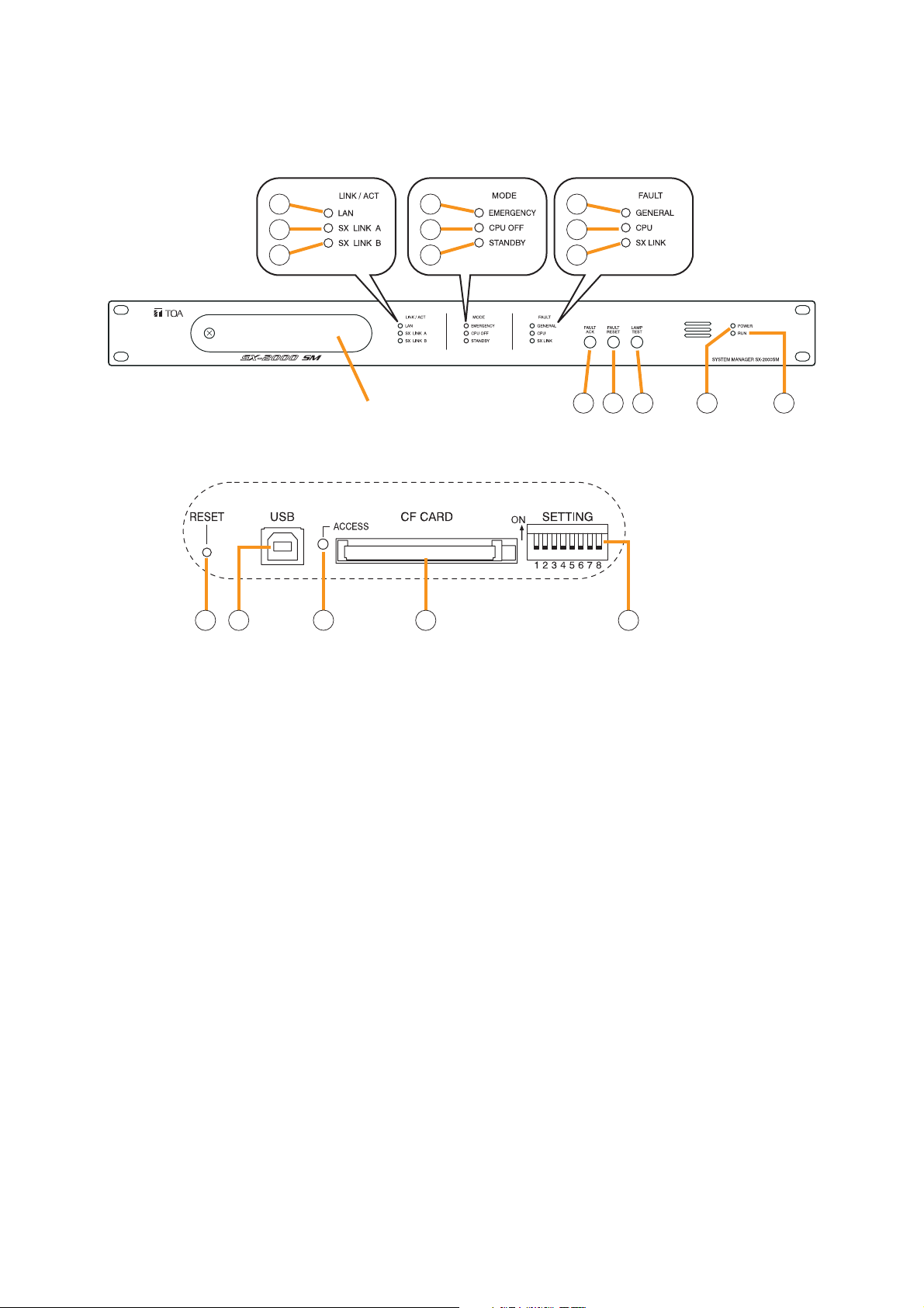
1.1. SX-2000SM System Manager
[Front]
1. LAN Indicator [LAN] (Green)
Lights when the LAN connection terminal (31) on
the rear panel is connected, and flashes during
LAN communications.
2. SX Link A Indicator [SX LINK A] (Green)
Lights when the SX Link A terminal (29) on the
rear panel is connected, and flashes while
communications are being performed via the SX
Link A terminal.
3. SX Link B Indicator [SX LINK B] (Green)
Lights when the SX Link B terminal (29) on the
rear panel is connected, and flashes while
communications are being performed via the SX
Link B terminal.
4. Emergency Indicator [EMERGENCY] (Red)
Lights while the general urgency all-call is being
made (p. 68) or when the SX-2000 system is in an
emergency condition, and flashes when a 24 V
emergency cutoff* state occurs involving any SX2000AO within the system.
* In the SX-2000 system, a 24 V emergency cutoff
input terminal that allows control of an
emergency audio input is provided on the SX2000AO's rear panel. When the SX-2000 system
is combined with another emergency broadcast
system, a 24 V DC is normally kept being
supplied to this emergency cutoff input terminal
and is cut off (24 V emergency cutoff function) in
emergency situations. This interrupts the
general-purpose broadcast from the SX-2000,
allowing the emergency broadcast system to
override it. (For details, see p. 56.)
5. CPU OFF Indicator [CPU OFF] (Red)
Lights while the general urgency all-call (CPU
OFF state) is being made (p. 68).
6. Standby Indicator [STANDBY] (Yellow)
Lights when the SX-2000 system is operating on
the backup power supply during power failures.
It also lights when the system reset cannot be
performed using the SX-2000 Setting software.
Note that if the standby indicator lights, it is not
possible to restart your SX-2000SM using the
Setting software.
To perform system reset, press the Reset key (15)
inside the protective cover to restart.
7. General Indicator [GENERAL] (Yellow)
Lights while the general urgency all-call is being
made (p. 68) or when a failure is detected in the
SX-2000SM. Lights or flashes when a failure is
detected in the system.
SX-2000SM
1
2
3
Inside of the protective cover
15 16 18 1917
4
5
6
Protective cover
7
8
9
10 11 12 13 14
Page 7

7
8. CPU Indicator [CPU] (Yellow)
Lights while the general urgency all-call is being
made (p. 68) or when a failure is detected in the
SX-2000SM.
9. SX Link Indicator [SX LINK] (Yellow)
Flashes when a cable is connected to neither the
rear panel-mounted SX Link terminal A nor B.
10. Fault Ack Key [FAULT ACK]
The buzzer will sound when a failure is detected
in the SX-2000 system. Press this key to stop the
buzzer.
11. Fault Reset Key [FAULT RESET]
Pressing this key resets the failure information
(the buzzer and fault indicators) for the entire
SX-2000 system.
Set the mode for operation method using DIP
switch 4 (19).
12. Lamp Test Key [LAMP TEST]
Used to test each indicator on the front panel of
the SX-2000SM.
All Mode and Fault indicators (4) – (9) remain lit
and the buzzer sounds as long as this key is
pressed.
13. Power Indicator [POWER] (Blue)
Lights when the power is switched on.
14. RUN Indicator [RUN] (Green)
Normally flashes continuously.
Goes off while the general urgency all-call is
being made (p. 68).
15. Reset Key [RESET]
Pressing this key reactivates the SX-2000SM.
The entire system, including the SX-2000AI, SX2100AI, SX-2000AO, and SX-2100AO is
reactivated.
Notes
• Reactivating the system stops broadcasts
currently in progress.
• Do not keep pressing the key for over 1
second. The unit cannot operate.
If the unit operation is suspended, press the
Reset key for less than one second again.
16. USB Port [USB]
This port is not used.
17. CF Card Access Indicator [ACCESS] (Green)
Flashes while reading from or writing to a CF
card.
Note
Do not remove and reinsert the CF card nor
operate the DIP switch (19) while this indicator is
flashing.
18. CF Card Slot [CF CARD]
Use this slot to insert the CF card to operate
settings data or write log data to the card.
• For settings data operation, see p. 140.
• For the method of writing log data, see p. 144.
Note
Removing and reinserting the CF card requires
DIP switch settings. If the CF card is removed
and reinserted without performing correct DIP
switch settings, this may cause settings data loss
or damage the card.
19. DIP Switch [SETTING]
• Switch 1
Used to read log data (p. 144).
ON: Allows log data to be written into the CF
card.
OFF: Normally select this position.
• Switch 2
Used to perform CF card access settings
(p. 140).
ON: Stops access to the CF card.
OFF: Normally select this position.
• Switch 3
Set whether or not to enable online control
using the SX-2000 Setting Software (p. 49).
ON: Disables online writing of settings data
and system reset.
OFF: Normally select this position.
• Switch 4
Set the method of operation to reset the failure
information (the buzzer and fault indicators)
with the FAULT RESET key (11) (p. 50).
In the same manner as the FAULT RESET key
operation, the failure information can also be
reset by shorting the RES terminals of the Data
input terminals (26) at the timing set here.
ON: Sets to the accidental operation
prevention mode.
OFF: Sets to the one touch mode.
(For the operation methods in each individual
mode, see the separate Operating Instructions,
"Detecting Fault.")
• Switches 5 – 8
These switches are not used.
Note
Switches 1 – 8 are set to the OFF position by
default.
SX-2000SM
Page 8
8
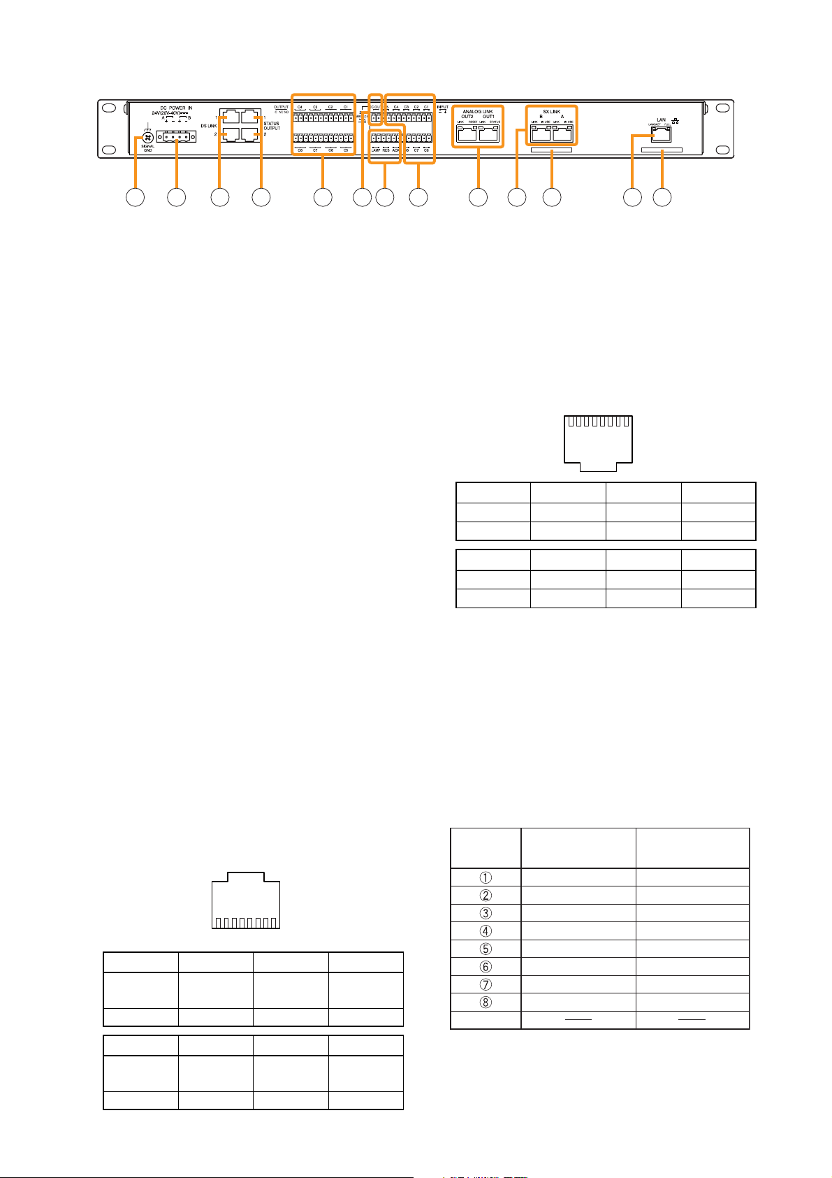
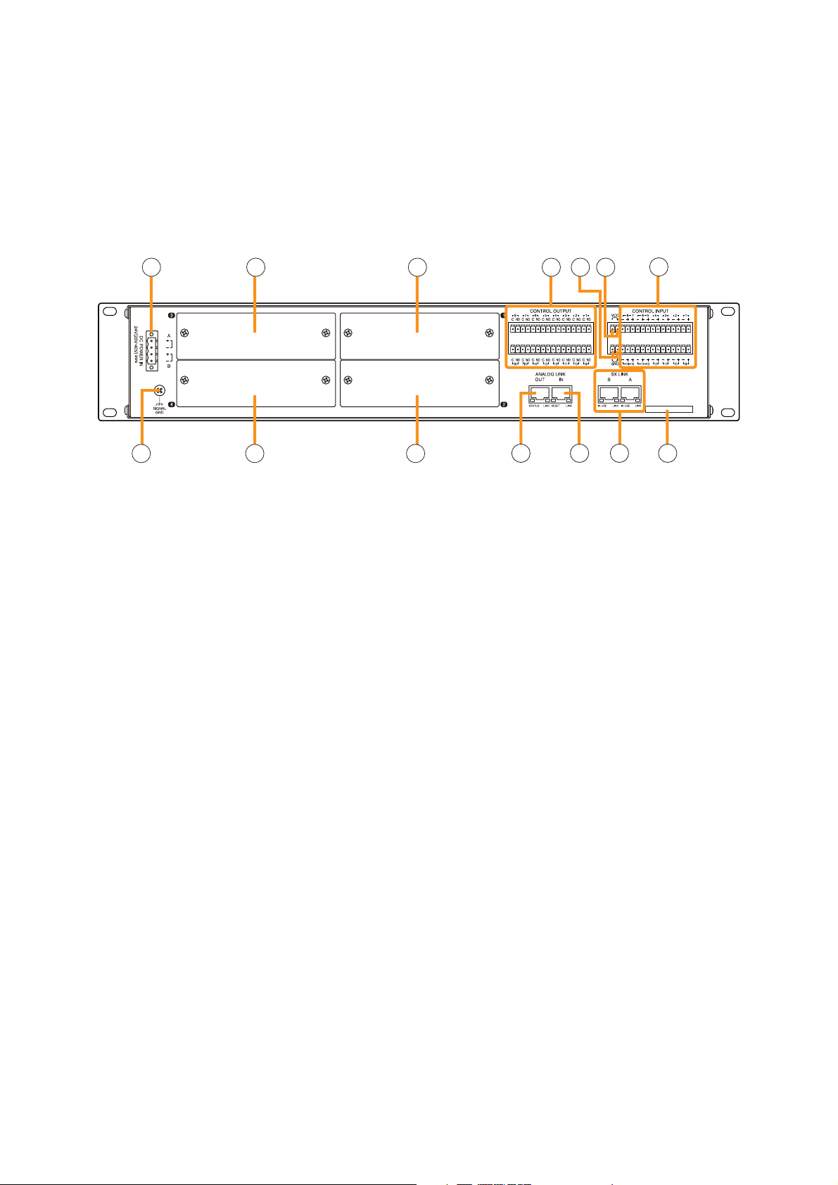
[Rear]
20. Functional Earth Terminal [SIGNAL GND]
Hum noise may be generated when external
equipment is connected to the unit. Connecting
this terminal to the functional earth terminal of
the external equipment may reduce the hum
noise.
Note: This terminal is not for protective earth.
21. DC Power Input Terminal [DC POWER IN]
Connect an optional DC power supply unit to this
terminal. Select the DC power supply source with
consideration given to the current power
consumption of the system the SX-2000SM is to
be connected to. When not using a redundant
power system*, connect the [+] terminal of input
A to the [+] terminal of input B, and the [–]
terminal of input A to the [–] terminal of input B.
(
Refer to the Instruction Manual attached to the
VX-2000DS.
)
* A method of connecting separate power
sources to each power input or connecting the
commercial power supply and backup power
supply separately to each power input to
prevent the system from going down when a
cable is broken or power fails.
22. DS Link Terminals [DS LINK]
Connect either terminal to the DS-SF Link
terminal of the VX-2000DS.
23. Status Output Terminals [STATUS OUTPUT]
Relay make contact outputs. Each contact
capacity is rated at 40 V DC for withstand
voltage, and 2 mA – 300 mA for control current.
The number of outputs is 4. The RJ45
connector's pin arrangement is as follows:
[Upper row]
• CPU FAULT
CPU irregularity in progress:
Pin 1 – Pin 2 shorted
Normal: Pin 1 – Pin 3 shorted
• GENERAL FAULT
Some irregularity in progress:
Pin 5 – Pin 7 shorted
Normal: Pin 5 – Pin 8 shorted
[Lower row]
• BUZZER
Buzzer ON: Pin 1 – Pin 2 shorted
Buzzer OFF: Pin 1 – Pin 3 shorted
• CPU OFF
Remote microphone-initiated general urgency
all-call broadcasts in progress:
Pin 5 – Pin 7 shorted.
General urgency all-call broadcasts not initiated:
Pin 5 – Pin 8 shorted.
[RJ45 connector's pin No. vs. Cable color]
24. Control Output Terminals [OUTPUT C1 – C8]
Relay make contact outputs. Each contact
capacity is rated at 40 V DC for withstand
voltage, and 2 mA – 300 mA for control current.
Pin 8 Pin 7 Pin 6 Pin 5
GENERAL GENERAL Not used GENERAL
FAULT FAULT FAULT
NC NO COM
Pin 4 Pin 3 Pin 2 Pin 1
Not used CPU CPU CPU
FAULT FAULT FAULT
NC NO COM
Pin 5 Pin 6 Pin 7 Pin 8
CPU OFF Not used CPU OFF CPU OFF
COM NO NC
Pin 1 Pin 2 Pin 3 Pin 4
BUZZER BUZZER BUZZER Not used
COM NO NC
SX-2000SM
21 22 23 24 25 26 27 28 29 30 31 3220
112345678
87654321
2
RJ45's
pin No.
Shield
Cable color Cable color
(T568B type) (T568A type)
Orange/White
Orange
Green/White
Blue
Blue/White
Green
Brown/White
Brown
Green/White
Green
Orange/White
Blue
Blue/White
Orange
Brown/White
Brown
Page 9
9
These terminals are controlled by the SX-2000
Setting Software. (See the separate Setting
Software Instructions, "Pattern Settings.")
25. 24V DC Output Terminals [DC OUT]
These terminals can provide up to 100 mA of 24
V DC power to connected external equipment.
26. Data Input Terminals [ACK/RES/LAMP]
Photo coupler inputs. A current of approximately
2 mA flows when shorted, and the voltage
becomes approximately 24 V DC when opened.
• ACK
The buzzer may sound when a failure is
detected in the SX-2000SM.
Short the ACK terminals to stop the buzzer.
If a failure occurs while ACK is on, it is
automatically received.
These terminals serve the same function as the
front-mounted FAULT ACK key (10).
• RES
In accordance with the DIP switch 4 (19)
setting, shorting these terminals resets once
the failure information (the buzzer and fault
indicators) of the SX-2000SM.
These terminals serve the same function as the
front-mounted FAULT RESET key (11).
• LAMP
Used to test the indicators on the SX-2000SM's
front panel. All MODE and FAULT indicators (4)
– (9) remain lit and the buzzer sounds as long
as these terminals are set to ON.
27. Control Input Terminals [INPUT C1 – C8]
Photo coupler inputs. A current of approximately
2 mA flows when shorted, and the voltage
becomes approximately 24 V DC when opened.
Functions can be assigned to these terminals
using the SX-2000 Setting Software. (See the
separate Setting Software Instructions, "Event
Settings.")
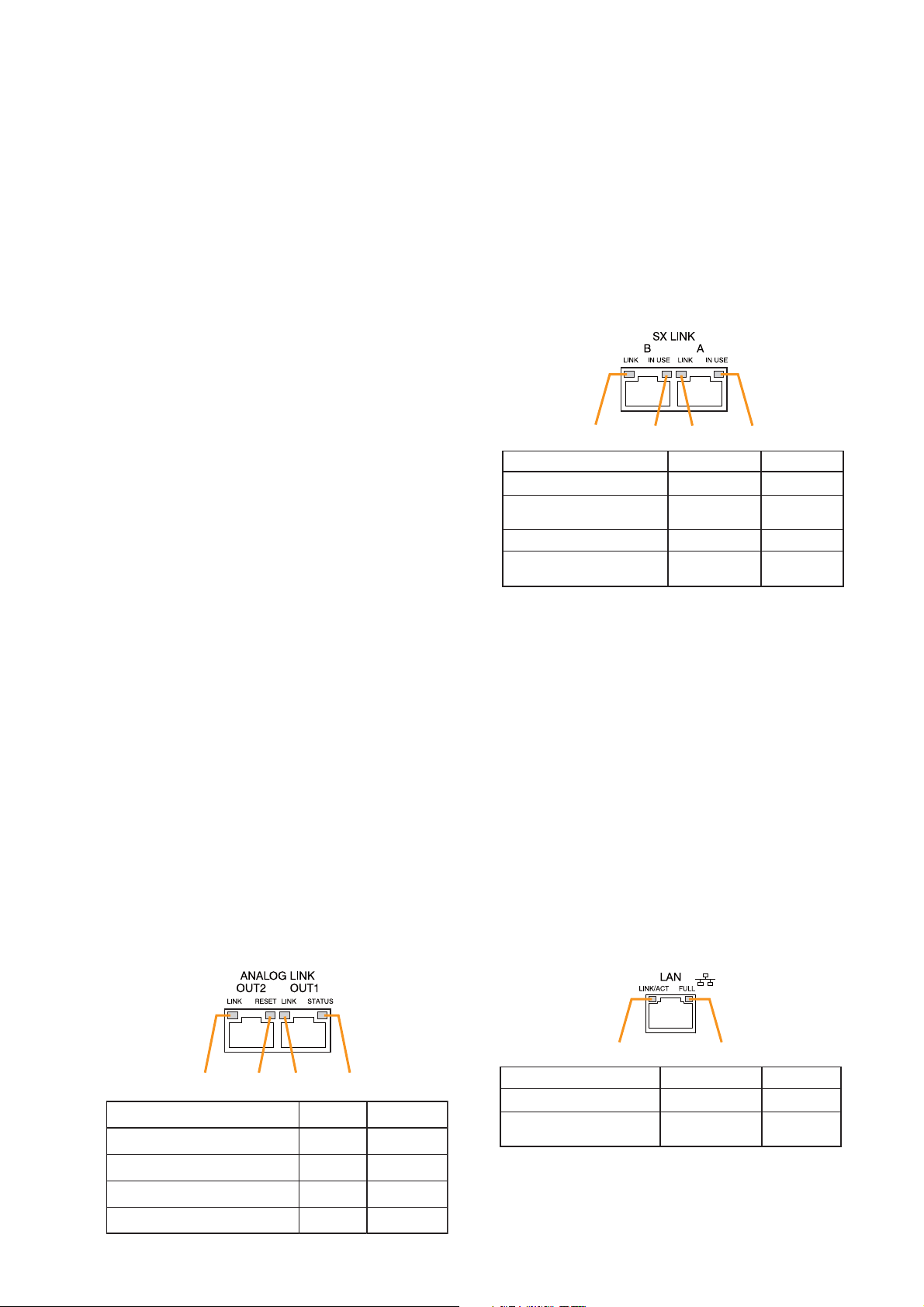
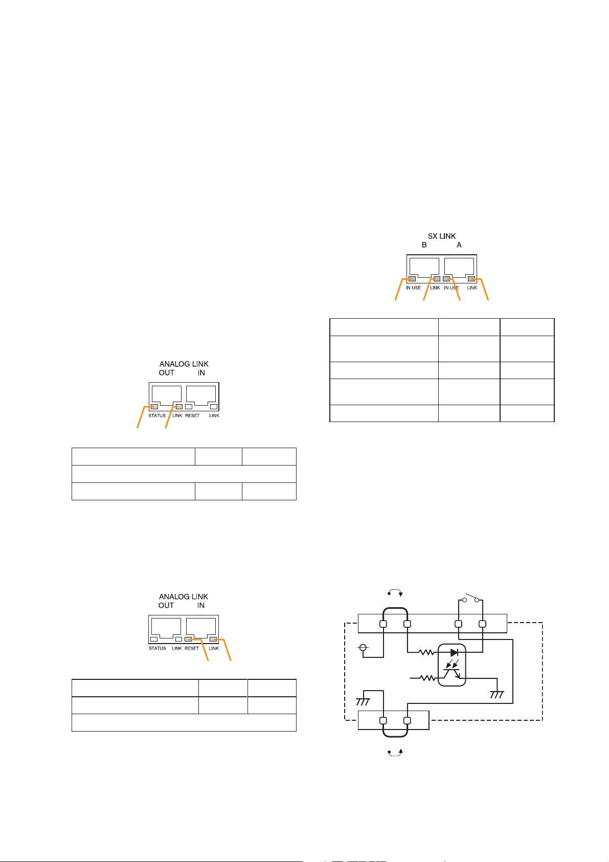
28. Analog Link Output Terminals
[ANALOG LINK OUT 1/2]
Connect these terminals to the analog link input
terminals of the SX-2000AI, SX-2100AI, SX2000AO, or SX-2100AO.
29. SX Link Terminals [SX LINK A/B]
Use switching hubs to connect between the SX
link terminals of the SX-2000SM, SX-2000AI,
SX-2100AI, SX-2000AO, and SX-2100AO.
Connect each of the SX Links A and B to the same
switching hub*, or to different switching hubs* that
have been connected in star configuration.
Notes
• Be sure to connect both terminals of A and B.
• After connection completion, press the Reset
key to reactivate the SX-2000SM.
* Contact your TOA dealer for more information
on switching hubs.
30. MAC Address for SX Link Connections
MAC address to be used for SX link connection.
31. LAN Connection Terminal [LAN]
Used when setting times to be recorded in
operation logs.
Connect this terminal to a switching hub that
supports the 10BASE-T or 100BASE-TX
standard. Since time settings can also be
performed via a PC, connect the PC to the
switching hub as well.
Notes
• Do not connect the switching hub to the LAN.
• Avoid directly connecting the SX-2000SM to
the PC via a cross cable.
(See the separate Setting Software Instructions
"Basic Settings" for settings related to the SX2000SM's IP address, etc.)
31. MAC Address for LAN Connection
A 12-digit hexadecimal address number peculiar
to and assigned to the network-connected unit.
SX-2000SM
1234
Function
1. B connection confirmation
2. B operation in progress
indication
3. A connection confirmation
4. A operation in progress
indication
LED On/Flashing
Connected
Operating
Connected
Operating
LED Off
Unconnected
Not operating
Unconnected
Not operating
1234
Function LED On LED Off
1. OUT 2 connection confirmation
2. OUT RESET output
3. OUT 1 connection confirmation
4. OUT STANDBY start output
Connected
Resetting
Connected
Start
Unconnected
Normal
Unconnected
Normal
12
Function LED On/Flashing LED Off
1. Connection confirmation
2. Full duplex
communication detection
Connected
Detected
Unconnected
Undetected
Page 10
10
1.2. SX-2000AI Audio Input Unit
[Front]
1. Monitor Speaker
Allows any input channel to be monitored.
2. Function Keys [F1, F2, F3, F4]
Pressing a function key executes the function that
has been assigned to that key using the SX-2000
Setting Software.
(See the separate Setting Software Instructions,
"Event Settings.")
3. Fluorescent Display
The default display shows device numbers and
firmware versions.
Displays the SX-2000AI's current operation status,
input level, etc. (See the separate Operating
Instructions, "SX-2000AI Audio Input Unit.")
4. Menu Key [MENU]
Pressing this key displays the fluorescent display's
menu screen. Whenever this key is pressed, the
screen returns to the default display for whatever
portion of the menu screen is displayed.
5. Cancel Key [ /CANCEL]
Used to switch the menu screen.
6. Minus Key [–]
Used to switch the menu screen. When the
Monitor ON/OFF Key (15) is set to ON, use this
key to select which channel to monitor.
The selected channel number decreases by one
each time this key is pressed.
7. Plus Key [+]
Used to switch the menu screen. When the
Monitor ON/OFF Key (15) is set to ON, use this
key to select which channel to monitor.
The selected channel number increases by one
each time this key is pressed.
8. OK Key [OK/ ]
Used to switch the menu screen.
9. Power Indicator [POWER] (Blue)
Lights when the power is switched on.
10. CPU OFF Indicator [CPU OFF] (Red)
Lights while the general urgency all-call (CPU
OFF state) is being made (p. 68).
SX-2000AI
1 2 3 114 5 6 7 8 9 10
Protective cover
12 13 14 15
Inside of the protective cover
1
0
2
F
3
E
D
C
6
B
7
A
8
9
16 18 1917
1
0
2
F
3
E
4
4
D
5
5
C
6
B
7
A
8
9
20
Device No.
AI– 1 VER300
Firmware version
..
Page 11

11
11. Standby Indicator [STANDBY] (Green)
Lights while the unit is being initialized at poweron or at reset.
Flashes when the fluorescent display is in light
shutoff mode and the light stays unlit.
Lights when the SX-2000 system is operating on
the backup power supply during power failures.
12. Input Volume Controls [INPUT 1 – 8]
Adjust the input volume of each input channel.
Rotating the control fully counterclockwise mutes
the input sound source connected to that
channel and causes the input ON/OFF indicator
(28) on the fluorescent display to turn off.
When an input channel's "Type" is set to
"Emergency" on the SX-2000 Setting software,
the input signal source is made to bypass this
Input volume control. (See the separate Setting
Software Instructions, "System Settings.")
13. Channel Keys [ON/OFF]
Turn each input channel on or off. The input
channel alternates between on and off each time
this key is pressed.
Other functions can also be assigned to each
key by using the SX-2000 Setting Software. (See
the separate Setting Software Instructions,
"Event Settings.")
When an input channel's "Type" is set to
"Emergency" on the SX-2000 Setting software,
the input signal source is made to bypass this
Channel key. (See the separate Setting Software
Instructions, "System Settings.")
14. Monitor Volume Control [MONITOR]
Adjusts the sound volume of the monitor speaker
(1).
15. Monitor ON/OFF Key [ON/OFF]
Enables or disables the audio monitor function
for the selected input channel. The monitor
function alternates between on and off each time
this key is pressed.
16. USB Port [USB]
This port is not used.
17. RUN Indicator [RUN] (Green)
Normally flashes continuously.
18. ID Switch [ID NUMBER]
Sets the SX-2000AI's device number.
(See p. 52.)
19. Reset Key [RESET]
Pressing this key resets the SX-2000AI.
Notes
• Resetting the SX-2000AI stops broadcasts in a
part of or all zones currently in progress via the
reset SX-2000AI.
• Do not keep pressing the key for over 1
second. The unit cannot operate.
If the unit operation is suspended, press the
Reset key for less than one second again.
20. DIP Switch [SETTING]
Performs key lock function settings.
(See p. 142.)
• Switch 1
ON: Disables operation of the front panel input
volume controls and channel keys.
OFF: Cancels key lock status.
• Switches 2 – 8
These switches are not used.
Note
Switches 1 – 8 are set to the OFF position by
default.
SX-2000AI
Page 12

12
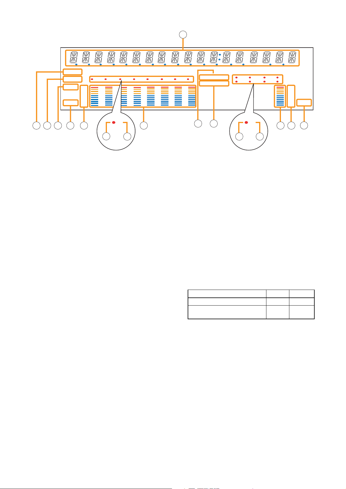
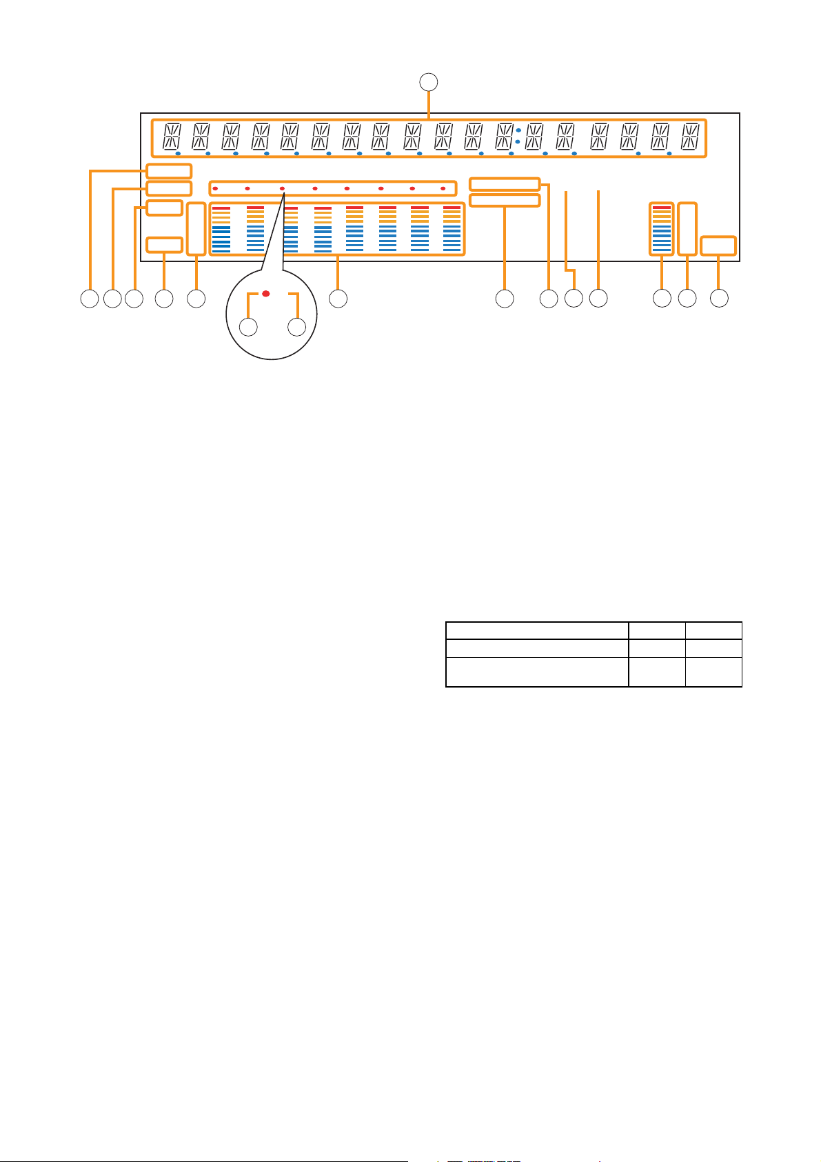
[Fluorescent Display]
21. Text Display Area
Displays the menu screen information when the
corresponding function key is pressed.
22. COM Indicator [COM]
Flashes to indicate a communications error.
23. Fault Indicator [FAULT]
Flashes when a system failure, incorrect system
configuration* or communications error is
detected. This indicator continues to flash until
failure conditions return to normal.
* When the system or module configuration
differs from the contents set by the SX-2000
Setting Software.
24. Input Level Meter Fader Indicator [FADER]
Lights when the input level meter indicates the
sound volume set using the SX-2000 Setting
Software or input volume control.
25. Input Level Meter Level Indicator [LEVEL]
Lights when the input level meter indicates the
level being input to the SX-2000AI.
26. Input Level Meter Scale
27. Input Indicator
The input channel to be monitored lights red.
28. Input ON/OFF Indicator
Indicates the unit's operating status when the
corresponding channel key is pressed.
The indicator state differs depending on the
function assigned to each channel key as
follows.
* The indicator state is "Unlit" when the input volume is muted.
29. Input Level Meter
Indicates the actual level or a set volume value
on each input channel.
30. Key Lock Indicator [KEY LOCK]
Lights when the input volume controls and
channel keys are locked. (See p. 142, "Key Lock
Settings and Cancellation.")
31. Emergency Indicator [EMERGENCY]
Lights when the SX-2000 system is in an
emergency condition.
32. Remote Microphone Output Status Indicator
Lights red continuously as long as announcements
are made from the RM-200SF, RM-200SA, or RM210 Remote Microphone.
Notes
• A timer-activated light shutoff function can be set for the fluorescent display using the SX-2000 Setting
Software. (See the separate Setting Software Instructions, "Basic Settings.")
When the light shutoff function has been set, if the SX-2000AI is not operated for 5 minutes or more, the
fluorescent display's light goes off and the standby indicator (11) begins to flash. Pressing any keys other
than the function keys on the front panel resets the screen display.
• Normally, the fluorescent display's light goes off at the time of the power failure.
• While the SX-2000 system is in an emergency condition, the fluorescent display's light does not go off even
if the power fails.
SX-2000AI
Function assigned to the channel key When ON When OFF
Input ON/OFF Lights* Unlit
General-purpose pattern broadcast's Flashes Lights
activation and termination
21
COM
FAULT
FADER
LEVEL LEVEL
–10
–20
–30
–40
OL
0
22 23 26
12 345678
27
33
2924 25
28
30
KEYLOCK
EMERGENCY
31
12 34
56 78
66
34 35
32 33
–10
–20
–30
–40
OL
0
36
Page 13
13
[Rear]
37. DC Power Input Terminal [DC POWER IN]
Connect an optional DC power supply unit to this
terminal. Select the DC power supply source with
consideration given to the current power
consumption of the system the SX-2000AI is to
be connected to. When not using a redundant
power system*, connect the [+] terminal of input
A to the [+] terminal of input B, and the [–]
terminal of input A to the [–] terminal of input B.
(
Refer to the Instruction Manual attached to the
VX-2000DS.
)
* A method of connecting separate power
sources to each power input or connecting the
commercial power supply and backup power
supply separately to each power input to
prevent the system from going down when a
cable is broken or power fails.
38. Module Slot 3 [3]
Slot for input channels 5 and 6.
39. Module Slot 1 [1]
Slot for input channels 1 and 2.
40. Functional Earth Terminal [SIGNAL GND]
Hum noise may be generated when external
equipment is connected to the unit. Connecting
this terminal to the functional earth terminal of
the external equipment may reduce the hum
noise.
Note: This terminal is not for protective earth.
41. Module Slot 4 [4]
Slot for input channels 7 and 8.
42. Module Slot 2 [2]
Slot for input channels 3 and 4.
43. Analog Link Output Terminal [ANALOG LINK
OUT]
Connect this terminal to the analog link input
terminal of the SX-2000AI, SX-2100AI, SX2000AO, or SX-2100AO.
44.
Analog Link Input Terminal [ANALOG LINK IN]
Connect this terminal to the analog link output
terminal of the SX-2000SM, SX-2000AI, SX2100AI, SX-2000AO, or SX-2100AO.
SX-2000AI
33.
Remote Microphone Connection Status Indicator
The device number of the Remote Microphone
connected to the SX-2000AI lights.
34. Monitor Level Meter
Indicates the sound volume level of the input
channel being monitored.
35. Monitor Level Meter Scale
Lights when the monitor ON/OFF key (15) is set
to ON.
36. Monitor ON/OFF Indicator [LEVEL]
Lights when the monitor ON/OFF key (15) is set
to ON.
3837
40 41 42 43 44 45
39
46
1 2
Function LED On LED Off
1. Not used
2. OUT connection confirmation Connected Unconnected
34
Function LED On LED Off
3. RESET input Resetting Normal
4. Not used
Page 14
14
45. SX Link Terminals [SX LINK A/B]
Use switching hubs to connect between the SX
link terminals of the SX-2000SM, SX-2000AI, SX2100AI, SX-2000AO, and SX-2100AO. Connect
each of the SX Links A and B to the same
switching hub*, or to different switching hubs* that
have been
connected in star configuration.
Notes
• Be sure to connect both terminals of A and B.
• After connection completion, press the Reset
key to reactivate the SX-2000AI.
* Contact your TOA dealer for more information
on switching hubs.
46. MAC Address
MAC address to be used for SX link connection.
SX-2000AI
1 234
Function
LED On/Flashing
LED Off
1. B operation in progress
indication
2. B connection confirmation Connected Unconnected
3. A operation in progress
indication
4. A connection confirmation Connected Unconnected
Operating Not operating
Operating Not operating
Page 15
15
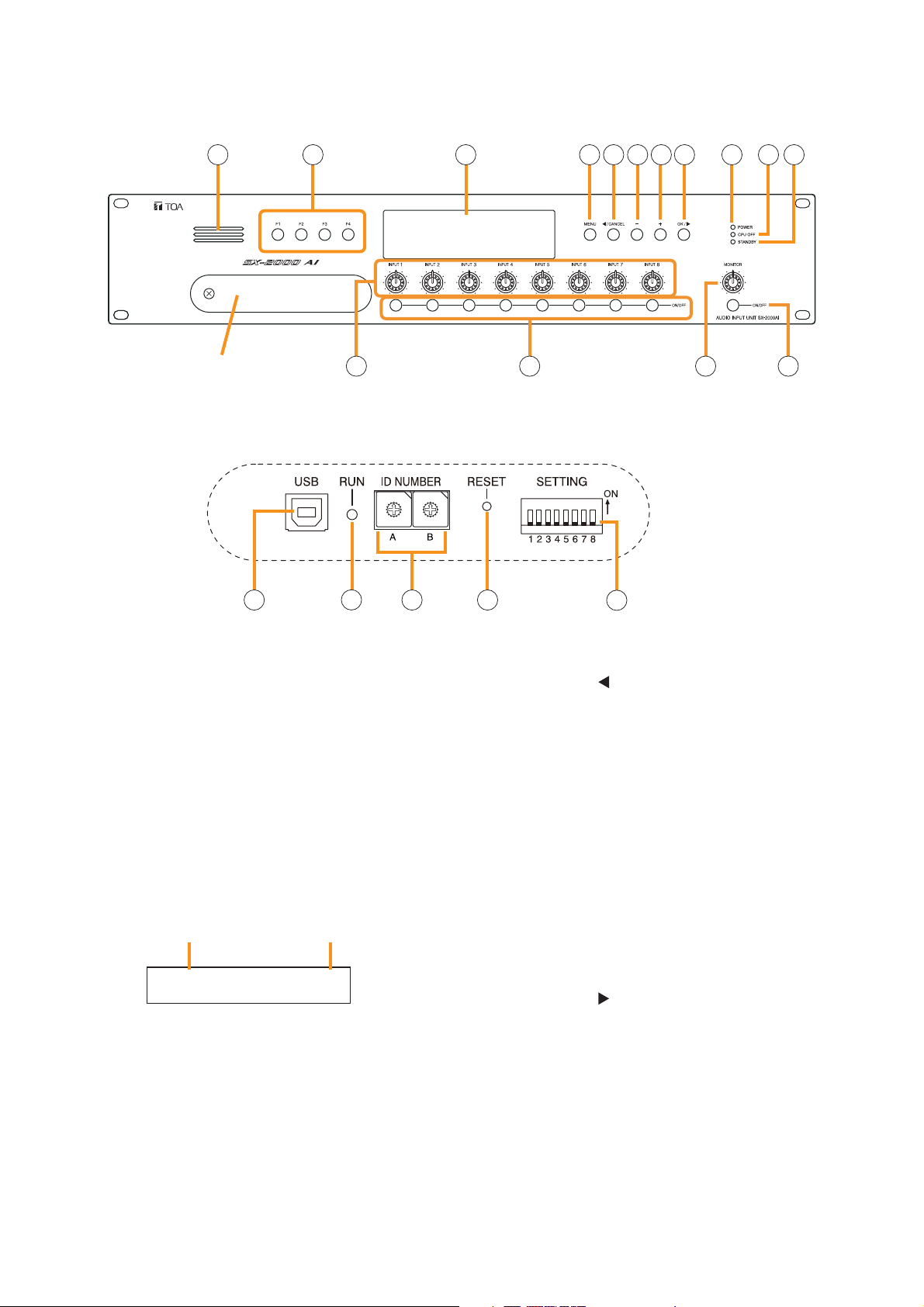
1.3. SX-2100AI Audio Input Unit
[Front]
1. Monitor Speaker
Allows any input channel to be monitored.
2. Function Keys [F1, F2, F3, F4]
Pressing a function key executes the function that
has been assigned to that key via the SX-2000
Setting Software.
(See the separate Setting Software Instructions,
"Event Settings.")
3. Fluorescent Display
The default display shows device numbers and
firmware versions.
Displays the SX-2100AI's current operation status,
input level, etc. (See the separate Operating
Instructions, "SX-2100AI Audio Input Unit.")
4. Menu Key [MENU]
Pressing this key displays the fluorescent display's
menu screen. Whenever this key is pressed, the
screen returns to the default display for whatever
portion of the menu screen is displayed.
5. Cancel Key [ /CANCEL]
Used to switch the menu screen.
6. Minus Key [–]
Used to switch the menu screen.
When the Monitor ON/OFF Key (15) is set to ON,
use this key to select which channel to monitor.
The selected channel number decreases by one
each time this key is pressed.
7. Plus Key [+]
Used to switch the menu screen.
When the Monitor ON/OFF Key (15) is set to ON,
use this key to select which channel to monitor.
The selected channel number increases by one
each time this key is pressed.
8. OK Key [OK/ ]
Used to switch the menu screen.
9. Power Indicator [POWER] (Blue)
Lights when the power is switched on.
10. CPU OFF Indicator [CPU OFF] (Red)
Lights while the general urgency all-call (CPU
OFF state) is being made (p. 68).
SX-2100AI
1 2 3 114 5 6 7 8 9 10
12 13 14 15
Protective cover
Inside of the protective cover
1
0
2
F
3
E
D
C
B
7
A
8
9
16 18 1917
Device No.
AI– 1 VER300
Firmware version
..
1
0
2
F
3
E
4
4
D
5
5
C
6
6
B
7
A
8
9
20
Page 16

16
11. Standby Indicator [STANDBY] (Green)
Lights while the unit is being initialized at poweron or at reset.
Flashes when the fluorescent display is in light
shutoff mode and the light stays unlit.
Lights when the SX-2000 system is operating on
the backup power supply during power failures.
12. Input Volume Controls [INPUT 1 – 8]
Adjust the input volume of each input channel.
Rotating the control fully counterclockwise mutes
the input sound source connected to that
channel and causes the input ON/OFF indicator
(28) on the fluorescent display to turn off.
When an input channel's "Type" is set to
"Emergency" on the SX-2000 Setting software,
the input signal source is made to bypass this
Input volume control. (See the separate Setting
Software Instructions, "System Settings.")
13. Channel Keys [ON/OFF]
Turn each input channel on or off. The input
channel alternates between on and off each time
this key is pressed.
Other functions can also be assigned to each
key by using the SX-2000 Setting Software. (See
the separate Setting Software Instructions,
"Event Settings.")
When an input channel's "Type" is set to
"Emergency" on the SX-2000 Setting software,
the input signal source is made to bypass this
Channel key. (See the separate Setting Software
Instructions, "System Settings.")
14. Monitor Volume Control [MONITOR]
Adjusts the sound volume of the monitor speaker
(1).
15. Monitor ON/OFF Key [ON/OFF]
Enables or disables the audio monitor function
for the selected input channel. The monitor
function alternates between on and off each time
this key is pressed.
16. USB Port [USB]
This port is not used.
17. RUN Indicator [RUN] (Green)
Normally flashes continuously.
18. ID Switch [ID NUMBER]
Sets the SX-2100AI's device number.
(See p. 52.)
19. Reset Key [RESET]
Pressing this key resets the SX-2100AI.
Notes
• Resetting the SX-2100AI stops broadcasts in a
part of or all zones currently in progress via the
reset SX-2100AI.
• Do not keep pressing the key for over 1
second. The unit cannot operate.
If the unit operation is suspended, press the
Reset key for less than one second again.
20. DIP Switch [SETTING]
Performs key lock function settings.
(See p. 142.)
• Switch 1
ON: Disables operation of the front panel input
volume controls and channel keys.
OFF: Cancels key lock status.
• Switches 2 – 8
These switches are not used.
Note
Switches 1 – 8 are set to the OFF position by
default.
SX-2100AI
Page 17
17
[Fluorescent Display]
21. Text Display Area
Displays the menu screen information when the
corresponding function key is pressed.
22. COM Indicator [COM]
Flashes to indicate a communications error.
23. Fault Indicator [FAULT]
Flashes when a system failure, incorrect system
configuration* or communications error is
detected. This indicator continues to flash until
failure conditions return to normal.
* When the system or module configuration
differs from the contents set by the SX-2000
Setting Software.
24. Input Level Meter Fader Indicator [FADER]
Lights when the input level meter indicates the
sound volume set using the SX-2000 Setting
Software or input volume control.
25. Input Level Meter Level Indicator [LEVEL]
Lights when the input level meter indicates the
level being input to the SX-2100AI.
26. Input Level Meter Scale
27. Input Indicator
The input channel to be monitored lights red.
28. Input ON/OFF Indicator
Indicates the unit's operating status when the
corresponding channel key is pressed.
The indicator state differs depending on the
function assigned to each channel key as
follows.
* The indicator state is "Unlit" when the input volume is muted.
29. Input Level Meter
Indicates the actual level or a set volume value
on each input channel.
30. Key Lock Indicator [KEY LOCK]
Lights when the input volume controls and
channel keys are locked. (See p. 142, "Key Lock
Settings and Cancellation.")
31. Emergency Indicator [EMERGENCY]
Lights when the SX-2000 system is in an
emergency condition.
32. Remote Microphone Output Status Indicator
Lights red continuously as long as announcements
are made from the RM-200SF, RM-200SA, or RM210 Remote Microphone.
Notes
• A timer-activated light shutoff function can be set for the fluorescent display using the SX-2000 Setting
Software. (See the separate Setting Software Instructions, "Basic Settings.")
When the light shutoff function has been set, if the SX-2100AI is not operated for 5 minutes or more, the
fluorescent display's light goes off and the standby indicator (11) begins to flash. Pressing any keys other
than the function keys on the front panel resets the screen display.
• Normally, the fluorescent display's light goes off at the time of the power failure.
• While the SX-2000 system is in an emergency condition, the fluorescent display's light does not go off even
if the power fails.
SX-2100AI
Function assigned to the channel key When ON When OFF
Input ON/OFF Lights* Unlit
General-purpose pattern broadcast's Flashes Lights
activation and termination
21
COM
FAULT
FADER
LEVEL LEVEL
22 23 26 2924 25
12 345678
OL
0
–10
–20
–30
–40
33
27
28
KEYLOCK
EMERGENCY
30
31
12 34
56 78
32
66
33
34 35
–10
–20
–30
–40
OL
0
36
Page 18
18
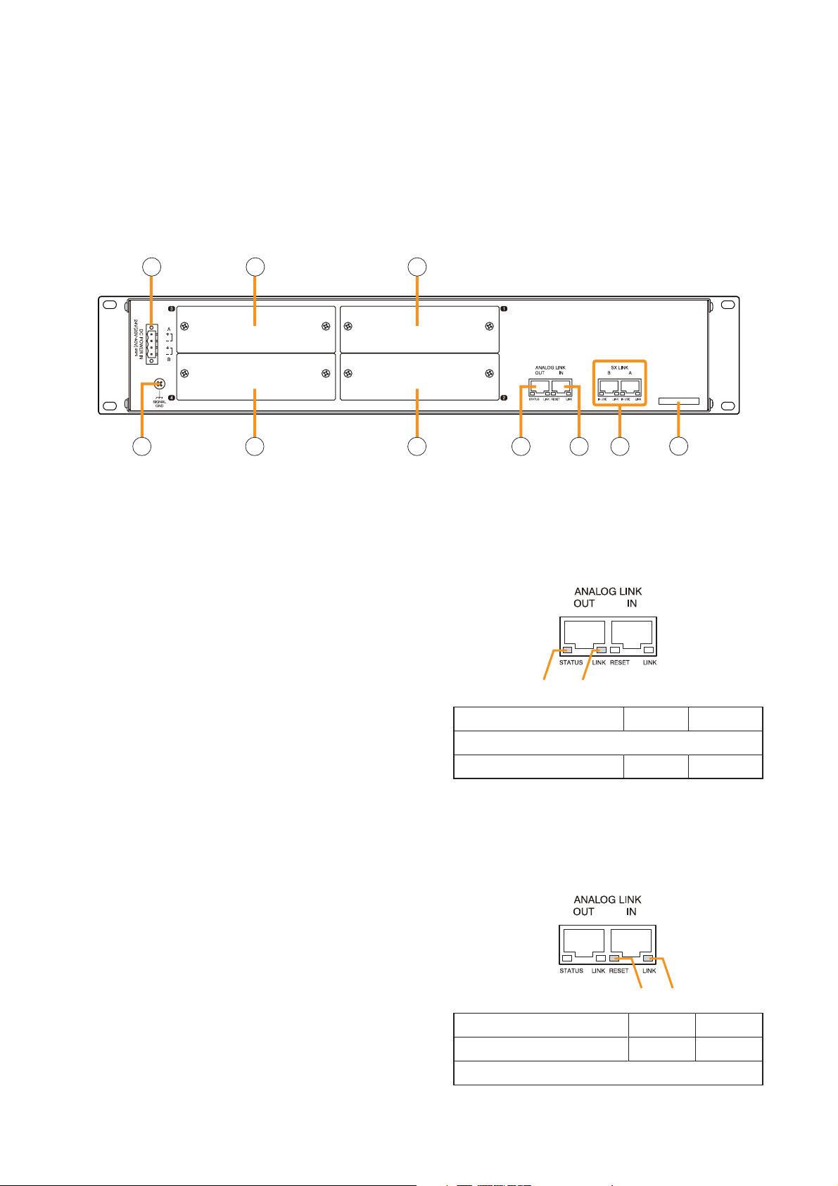
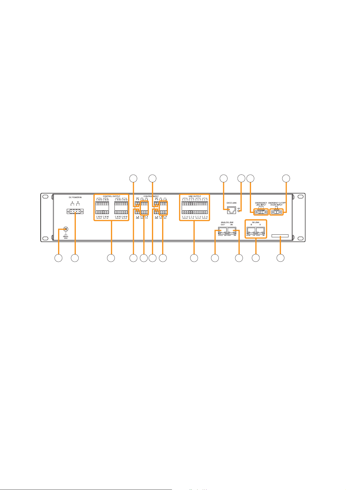
[Rear]
37. DC Power Input Terminal [DC POWER IN]
Connect an optional DC power supply unit to this
terminal. Select the DC power supply source with
consideration given to the current power
consumption of the system the SX-2100AI is to
be connected to. When not using a redundant
power system*, connect the [+] terminal of input
A to the [+] terminal of input B, and the [–]
terminal of input A to the [–] terminal of input B.
(
Refer to the Instruction Manual attached to the
VX-2000DS.
)
* A method of connecting separate power
sources to each power input or connecting the
commercial power supply and backup power
supply separately to each power input to
prevent the system from going down when a
cable is broken or power fails.
38. Module Slot 3 [3]
Slot for input channels 5 and 6.
39. Module Slot 1 [1]
Slot for input channels 1 and 2.
40. Functional Earth Terminal [SIGNAL GND]
Hum noise may be generated when external
equipment is connected to the unit. Connecting
this terminal to the functional earth terminal of
the external equipment may reduce the hum
noise.
Note: This terminal is not for protective earth.
41. Module Slot 4 [4]
Slot for input channels 7 and 8.
42. Module Slot 2 [2]
Slot for input channels 3 and 4.
43. Control Output Terminals
[CONTROL OUTPUT 1 – 16]
Relay make contact outputs.
All the contact outputs are of normally open type
when shipped from the factory.
Each output can be converted into normally
closed type by changing the internal jumper
setting. (See "Operation of Power Feed Jumper
and Isolation Jumper" on the next page.)
Each contact capacity is rated at 40 V DC for
withstand voltage, and 2 mA – 300 mA for
control current. These terminals are controlled by
the SX-2000 Setting Software. (See the separate
Setting Software Instructions, "Pattern Settings.")
44. Isolation Jumper [GND]
The supplied removable terminal plug is
equipped with a jumper. When the jumper is
attached, the [–] terminals of all inputs (1 – 16)
are connected to the internal power supply.
Removing the jumper disconnects and isolates
these [–] terminals from this unit. (See
"Operation of Power Feed Jumper and Isolation
Jumper" on the next page.)
45. Power Feed Jumper [VCC]
The supplied removable terminal plug is
equipped with a jumper. When the jumper is
attached, the circuits of all control inputs (1 – 16)
are powered from inside the SX-2100AI.
Removing the jumper disconnects this internal
power supply and thus requires that power be
supplied externally to the circuit. (See "Operation
of Power Feed Jumper and Isolation Jumper" on
the next page.)
SX-2100AI
33. Remote Microphone Connection Status
Indicator
The device number of the Remote Microphone
connected to the SX-2100AI lights.
34. Monitor Level Meter
Indicates the sound volume level of the input
channel being monitored.
35. Monitor Level Meter Scale
Lights when the monitor ON/OFF key (15) is set
to ON.
36. Monitor ON/OFF Indicator [LEVEL]
Lights when the monitor ON/OFF key (15) is set
to ON.
3837 39
40 41 42
43 445045
46
47 48 49
Page 19
46. Control Input Terminals
[CONTROL INPUT 1 – 16]
Photo coupler inputs. A current of approximately
2 mA flows when shorted, and the voltage
becomes under 40 V DC when opened.
The input of 100 msec or greater is required to
operate. These contact inputs can be isolated
from the SX-2100AI unit by cutting the power
feed jumper (45) and the isolation jumper (44).
Each contact input when isolated is 40 V DC for
maximum applied voltage and approximately 2
mA for the loop current. Since each terminal is
equipped with a current limiter employing
constant current circuitry, there is no need to limit
current on the external equipment side. The [–]
terminals of all control inputs are common. Use
the SX-2000 Setting Software to assign functions
to these terminals. (See the separate Setting
Software Instructions, "Event Settings.")
47. Analog Link Output Terminal
[ANALOG LINK OUT]
Connect this terminal to the analog link input
terminal of the SX-2000AI, SX-2100AI, SX2000AO, or SX-2100AO.
48. Analog Link Input Terminal
[ANALOG LINK IN]
Connect this terminal to the analog link output
terminal of the SX-2000SM, SX-2000AI, SX2100AI, SX-2000AO, or SX-2100AO.
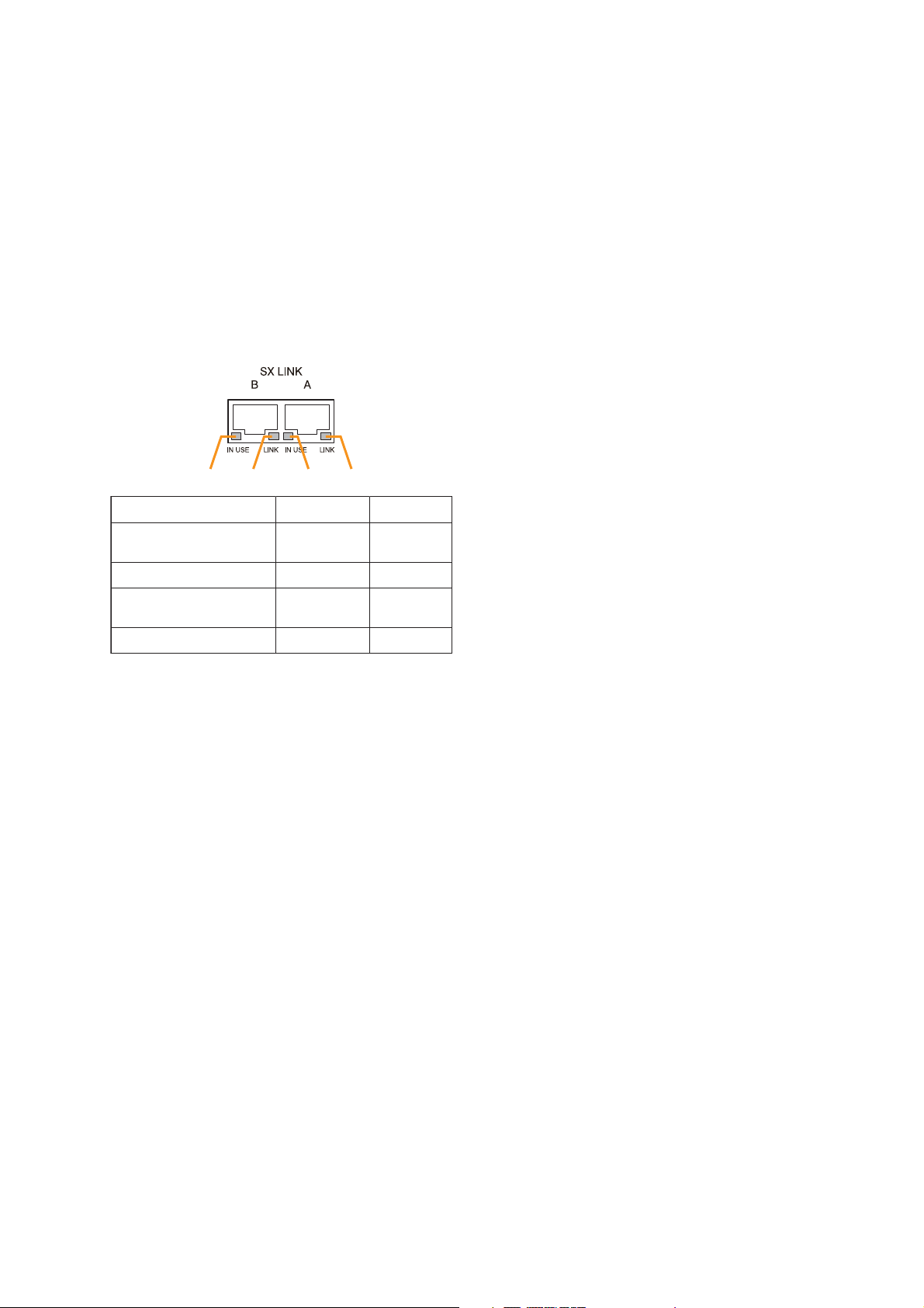
49. SX Link Terminals [SX LINK A/B]
Use switching hubs to connect between the SX
link terminals of the SX-2000SM, SX-2000AI, SX2100AI, SX-2000AO, and SX-2100AO. Connect
each of the SX Links A and B to the same
switching hub*, or to different switching hubs* that
have been
connected in star configuration.
Notes
• Be sure to connect both terminals of A and B.
• After connection completion, press the Reset
key to reactivate the SX-2100AI.
* Contact your TOA dealer for more information
on switching hubs.
50. MAC Address
MAC address to be used for SX link connection.
19
SX-2100AI
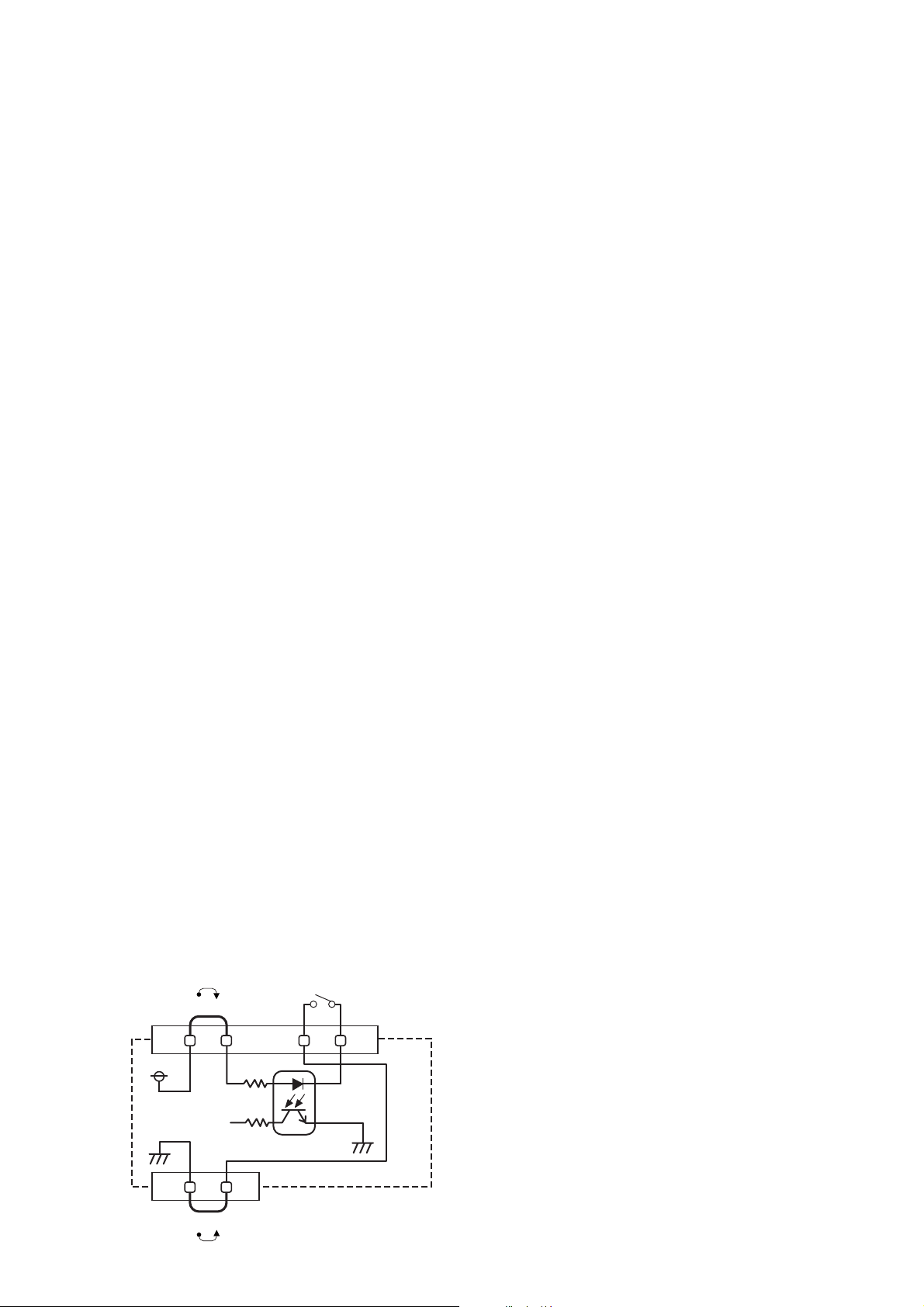
[Operation of Power Feed Jumper and
Isolation Jumper]
1 234
Function
1. B operation in progress
indication
2. B connection confirmation Connected Unconnected
LED On/Flashing
Operating Not operating
LED Off
1 2
Function LED On LED Off
1. Not used
2. OUT connection confirmation Connected Unconnected
34
3. A operation in progress
indication
4. A connection confirmation Connected Unconnected
Operating Not operating
VCC
Power feed jumper
Control input
-
+
Function LED On LED Off
3. RESET input Resetting Normal
4. Not used
Photo coupler
Internal circuit
Isolation jumper
GND
Page 20
20
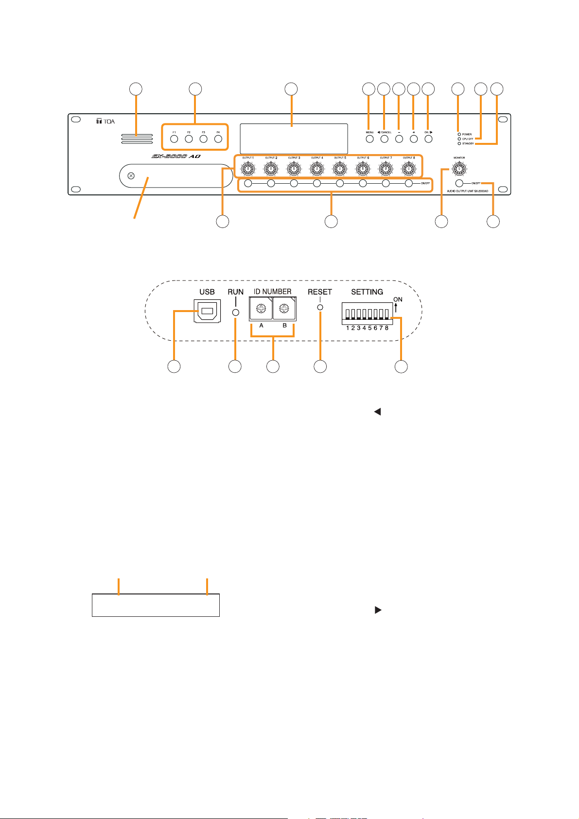
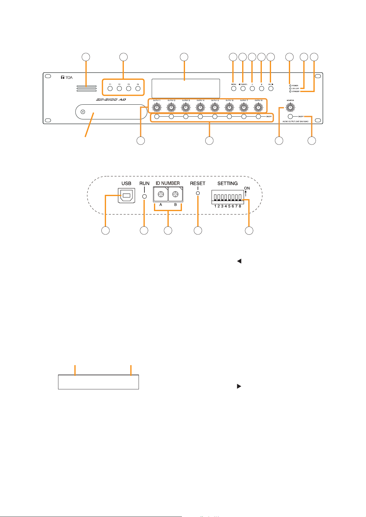
1.4. SX-2000AO Audio Output Unit
[Front]
1. Monitor Speaker
Allows any output channel to be monitored.
2. Function Keys [F1, F2, F3, F4]
Pressing a function key executes the function that
has been assigned to that key via the SX-2000
Setting Software.
(See the separate Setting Software Instructions,
"Event Settings.")
3. Fluorescent Display
The default display shows device numbers and
firmware versions.
Displays the SX-2000AO's current operation
status, output level, etc. (See the separate
Operating Instructions, "SX-2000AO Audio Output
Unit.")
4. Menu Key [MENU]
Pressing this key displays the fluorescent display's
menu screen. Whenever this key is pressed, the
screen returns to the default display for whatever
portion of the menu screen is displayed.
5. Cancel Key [ /CANCEL]
Used to switch the menu screen.
6. Minus Key [–]
Used to switch the menu screen. When the
Monitor ON/OFF Key (15) is set to ON, use this
key to select which channel to monitor. The
selected channel number decreases by one each
time this key is pressed.
7. Plus Key [+]
Used to switch the menu screen. When the
Monitor ON/OFF Key (15) is set to ON, use this
key to select which channel to monitor. The
selected channel number increases by one each
time this key is pressed.
8. OK Key [OK/ ]
Used to switch the menu screen.
9. Power Indicator [POWER] (Blue)
Lights when the power is switched on.
10. CPU OFF Indicator [CPU OFF] (Red)
Lights while the general urgency all-call (CPU
OFF state) is being made (p. 68).
SX-2000AO
1 2 3 114 5 6 7 8 9 10
Protective cover
12 13 14 15
Inside of the protective cover
16 18 1917
1
1
0
0
2
2
F
F
3
E
D
C
B
A
3
E
4
4
D
5
5
C
6
6
B
7
7
A
8
8
9
9
20
AO– 1 VER300
Device No. Firmware version
..
Page 21

21
11. Standby Indicator [STANDBY] (Green)
Lights while the unit is being initialized at poweron or at reset.
Flashes when the fluorescent display is in light
shutoff mode and the light stays unlit.
Lights when the SX-2000 system is operating on
the backup power supply during power failures.
12. Output Volume Controls [OUTPUT 1 – 8]
Adjust the output volume of each output channel.
Rotating the control fully counterclockwise mutes
the output volume and causes the output
ON/OFF indicator (28) on the fluorescent display
to turn off.
Signals on the output channel being used for
emergency broadcast are made to bypass this
Output volume control.
13. Channel Keys [ON/OFF]
Turn each output channel on or off. The output
channel alternates between on and off each time
this key is pressed.
Other functions can also be assigned to each
key by using the SX-2000 Setting Software. (See
the separate Setting Software Instructions,
"Event Settings.")
Signals on the output channel being used for
emergency broadcast are made to bypass this
Channel key.
14. Monitor Volume Control [MONITOR]
Adjusts the sound volume of the monitor speaker
(1).
15. Monitor ON/OFF Key [ON/OFF]
Enables or disables the audio monitor function
for the selected output channel. The monitor
function alternates between on and off each time
this key is pressed.
16. USB Port [USB]
This port is not used.
17. RUN Indicator [RUN] (Green)
Normally flashes continuously.
18. ID Switch [ID NUMBER]
Sets the SX-2000AO's device number.
(See p. 55.)
19. Reset Key [RESET]
Pressing this key resets the SX-2000AO.
Notes
• Resetting the SX-2000AO stops broadcasts
currently in progress via the reset SX-2000AO.
• Do not keep pressing the key for over 1
second. The unit cannot operate.
If the unit operation is suspended, press the
Reset key for less than one second again.
20. DIP Switch [SETTING]
• Switch 1
Performs key lock function settings.
(See p. 143.)
ON: Disables operation of the front panel
output volume controls and channel keys.
OFF: Cancels key lock status.
• Switches 2 – 7
These switches are not used.
• Switch 8
Enables or disables the 24 V emergency cutoff
input on the rear panel. (See p. 56.)
Note
Switches 1 – 8 are set to the OFF position by
default.
SX-2000AO
Page 22
22
[Fluorescent Display]
21. Text Display Area
Displays the menu screen information when the
corresponding function key is pressed.
22. COM Indicator [COM]
Flashes to indicate a communications error.
23. Fault Indicator [FAULT]
Flashes when a system failure, incorrect system
configuration*1or communications error is
detected. This indicator continues to flash until
failure conditions return to normal.
*
1
When the system or module configuration
differs from the contents set by the SX-2000
Setting Software.
24. Output Level Meter Fader Indicator [FADER]
Lights when the output level meter indicates the
sound volume set using the SX-2000 Setting
Software or output volume control.
25. Output Level Meter Level Indicator [LEVEL]
Lights when the output level meter indicates the
level being output from the SX-2000AO.
26. Output Level Meter Scale
27. Output Indicator
The output channel to be monitored lights red.
28. Output ON/OFF Indicator
Indicates the unit's operating status when the
corresponding channel key is pressed.
The indicator state differs depending on the
function assigned to each channel key as
follows.
* The indicator state is "Unlit" when the output volume is muted.
29. Output Level Meter
Indicates the actual level or a set volume value
on each output channel.
30. Emergency Indicator [EMERGENCY]
Lights when the SX-2000 system is in an
emergency condition.
When the 24 V emergency cutoff input*2is
enabled, this indicator flashes if the input
receives an emergency signal.
*
2
The SX-2000AO has a 24 V emergency cutoff
input terminal (49) on the rear panel, allowing
control of an emergency audio input. When the
SX-2000 system is combined with an
emergency broadcast system, a 24 V DC is
normally kept being supplied to this
emergency cutoff input terminal and is cut off
(24 V emergency cutoff function) in emergency
situations. This interrupts the general-purpose
broadcast from the SX-2000 system, allowing
the emergency broadcast system to override it.
(For details, see p. 56.)
Notes
• A timer-activated light shutoff function can be set for the fluorescent display using the SX-2000 Setting
Software. (See the separate Setting Software Instructions, "Basic Settings.")
When the light shutoff function has been set, if the SX-2000AO is not operated for 5 minutes or more, the
fluorescent display's light goes off and the standby indicator (11) begins to flash. Pressing any keys other
than the function keys on the front panel resets the screen display.
• Normally, the fluorescent display's light goes off at the time of the power failure.
• While the SX-2000 system is in an emergency condition, the fluorescent display's light does not go off even
if the power fails.
SX-2000AO
Function assigned to the channel key When ON When OFF
Output ON/OFF Lights* Unlit
General-purpose pattern broadcast's Flashes Lights
activation and termination
21
COM
FAULT
FADER
LEVEL LEVEL
22 23 24 25 26 29 30 31
12 345678
OL
0
–10
–20
–30
–40
33
KEYLOCK
EMERGENCY
12
OL
0
–10
–20
–30
–40
32 33 34 35 36
27 28
Page 23
23
Note
When the 24 V Emergency cutoff input is set to
be disabled (not usable) with the DIP switch 8
inside the protective cover, the Emergency
indicator will not flash even if 24 V DC supply to
this input terminal is cut off.
31. Key Lock Indicator [KEY LOCK]
Lights when the output volume controls and
channel keys are locked. (See p. 143, "Key Lock
Settings and Cancellation.")
32. Control Input Unit Connection Indicator [1]
Indicates "1" when the SX-2000CI is connected
to the SX-2000AO.
33. Control Output Unit Connection Indicator [2]
Indicates "2" when the SX-2000CO is connected
to the SX-2000AO.
34. Monitor Level Meter
Indicates the sound volume level of the output
channel being monitored.
35. Monitor Level Meter Scale
Lights when the monitor ON/OFF key (15) is set
to ON.
36. Monitor ON/OFF Indicator [LEVEL]
Lights when the monitor ON/OFF key (15) is set
to ON.
[Rear]
37. Functional Earth Terminal [SIGNAL GND]
Hum noise may be generated when external
equipment is connected to the unit. Connecting
this terminal to the functional earth terminal of
the external equipment may reduce the hum
noise.
Note: This terminal is not for protective earth.
38. DC Power Input Terminal [DC POWER IN]
Connect an optional DC power supply unit to this
terminal. Select the DC power supply source with
consideration given to the current power
consumption of the system the SX-2000AO is to
be connected to. When not using a redundant
power system*, connect the [+] terminal of input
A to the [+] terminal of input B, and the [–]
terminal of input A to the [–] terminal of input B.
(
Refer to the Instruction Manual attached to the
VX-2000DS.
)
* A method of connecting separate power
sources to each power input or connecting the
commercial power supply and backup power
supply separately to each power input to
prevent the system from going down when a
cable is broken or power fails.
39. Control Output Terminals
[CONTROL OUTPUT 1 – 8]
Relay make contact outputs.
Each contact capacity is rated at 40 V DC for
withstand voltage, and 2 mA – 300 mA for
control current.
These terminals are controlled by the SX-2000
Setting Software. (See the separate Setting
Software Instructions, "Pattern Settings.")
40. Power Feed Jumper 2 [VCC]
The supplied removable terminal plug is
equipped with a jumper.
When the jumper is attached, the circuits of
control inputs 3, 4, 7, and 8 are powered from
inside the SX-2000AO.
Removing the jumper disconnects this internal
power supply and thus requires that power be
supplied externally to the circuit. (See "Operation
of Power Feed Jumper and Isolation Jumper" on
the next page.)
SX-2000AO
40
43
46
47 48 49
37 38 39
41 42 42
44 45
50 51
52 53
Page 24
41. Isolation Jumper 2 [GND]
The supplied removable terminal plug is
equipped with a jumper.
When the jumper is attached, the [–] terminals of
control inputs 3, 4, 7, and 8 are connected to the
internal power supply.
Removing the jumper disconnects and isolates
these [–] terminals from this unit. (See
"Operation of Power Feed Jumper and Isolation
Jumper" shown below.)
42. Control Input Terminals
[CONTROL INPUT 1 – 8]
Photo coupler inputs.
A current of approximately 2 mA flows when
shorted, and the voltage becomes under 40 V
DC when opened. The input of 100 msec or
greater is required to operate.
These contact inputs can be isolated from the
SX-2000AO unit by cutting power feed jumpers 1
(43) and 2 (40) and isolation jumpers 1 (44) and
2 (41). Each contact input when isolated is 40 V
DC for maximum applied voltage and
approximately 2 mA for the loop current.
Since each terminal is equipped with a current
limiter employing constant current circuitry, there
is no need to limit the current on the external
equipment side.
The [–] terminals of 1, 2, 5, and 6 are common,
while those of 3, 4, 7, and 8 are common.
Use the SX-2000 Setting Software to assign
functions to these terminals. (See the separate
Setting Software Instructions, "Event Settings.")
43. Power Feed Jumper 1 [VCC]
The supplied removable terminal plug is
equipped with a jumper.
When the jumper is attached, the circuits of
control inputs 1, 2, 5, and 6 are powered from
inside the SX-2000AO.
Removing the jumper disconnects this internal
power supply and thus requires that power be
supplied externally to the circuit. (See "Operation
of Power Feed Jumper and Isolation Jumper"
shown below.)
44. Isolation Jumper 1 [GND]
The supplied removable terminal plug is
equipped with a jumper.
When the jumper is attached, the [–] terminals of
control inputs 1, 2, 5, and 6 are connected to the
internal power supply.
Removing the jumper disconnects and isolates
these [–] terminals from this unit. (See
"Operation of Power Feed Jumper and Isolation
Jumper" shown below.)
45. Audio Output Terminals [LINE OUTPUT]
Output audio signals to be broadcast.
These outputs are electronically balanced, but
can be converted into transformer-balanced type
using optional IT-450 transformers. (See p. 57,
"Converting an output into a transformerbalanced output.")
Note
Each output cannot be converted into
unbalanced type as it is electronically balanced.
To convert each output into unbalanced type,
use an optional IT-450 transformer.
46. CI/CO Link Terminal [CI/CO LINK]
Connect this terminal to the CI/CO Link Data
Terminal of the SX-2000CI or SX-2000CO.
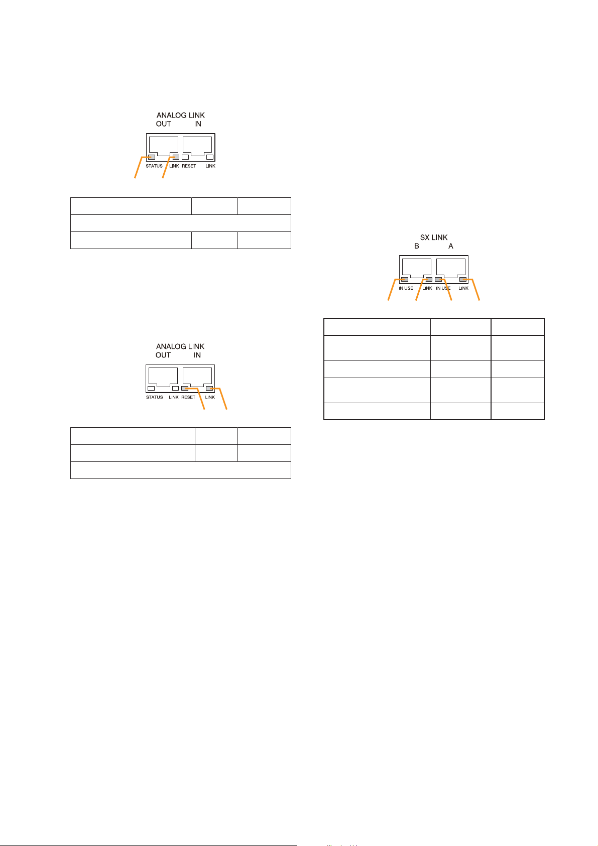
47.
CI/CO Link Connection Indicator [LINK] (Green)
Lights when the SX-2000CI or the SX-2000CO is
connected.
48. Emergency Audio Input Terminal
[EMERGENCY LINE INPUT]
Connect a voice evacuation system equipment to
this terminal. The input signal is routed to all
audio output terminals when the SX-2000AO is
turned off or 24 V DC is not applied to the 24 V
Emergency cutoff input terminal (49).
49. 24 V Emergency Cutoff Input Terminal
[EMERGENCY CUTOFF DC24 V INPUT]
Controls the Emergency audio input.
Input current is under 5 mA.
24
SX-2000AO
[Operation of Power Feed Jumper and Isolation Jumper]
VCC
Power feed jumper
Isolation jumper
GND
Control input
-
Photo coupler
+
Internal circuit
Page 25
25
50. Analog Link Output Terminal
[ANALOG LINK OUT]
Connect this terminal to the analog link input
terminal of the SX-2000AI, SX-2100AI, SX2000AO, or SX-2100AO.
51. Analog Link Input Terminal
[ANALOG LINK IN]
Connect this terminal to the analog link output
terminal of the SX-2000SM, SX-2000AI, SX2100AI, SX-2000AO, or SX-2100AO.
52. SX Link Terminals [SX LINK A/B]
Use switching hubs to connect between the SX
link terminals of the SX-2000SM, SX-2000AI, SX2100AI, SX-2000AO, and SX-2100AO. Connect
each of the SX Links A and B to the same
switching hub*, or to different switching hubs* that
have been
connected in star configuration.
Notes
• Be sure to connect both terminals of A and B.
• After connection completion, press the Reset
key to reactivate the SX-2000AO.
* Contact your TOA dealer for more information
on switching hubs.
53. MAC Address
MAC address to be used for SX link connection.
SX-2000AO
1 2
Function LED On LED Off
1. Not used
2. OUT connection confirmation Connected Unconnected
1 234
Function
LED On/Flashing
LED Off
34
Function LED On LED Off
3. RESET input Resetting Normal
4. Not used
1. B operation in progress
indication
2. B connection confirmation Connected Unconnected
3. A operation in progress
indication
4. A connection confirmation Connected Unconnected
Operating Not operating
Operating Not operating
Page 26
26
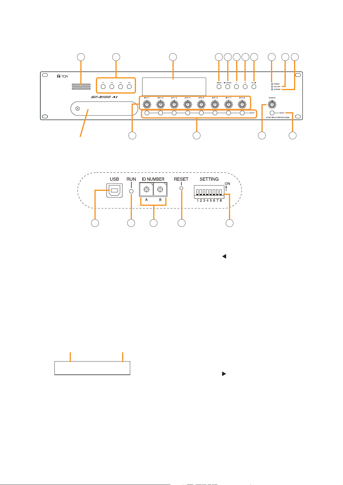
1.5. SX-2100AO Audio Output Unit
[Front]
1. Monitor Speaker
Allows any output channel to be monitored.
2. Function Keys [F1, F2, F3, F4]
Pressing a function key executes the function that
has been assigned to that key using the SX-2000
Setting Software.
(See the separate Setting Software Instructions,
"Event Settings.")
3. Fluorescent Display
The default display shows device numbers and
firmware versions.
Displays the SX-2100AO's current operation
status, output level, etc. (See the separate
Operating Instructions, "SX-2100AO Audio Output
Unit.")
4. Menu Key [MENU]
Pressing this key displays the fluorescent display's
menu screen. Whenever this key is pressed, the
screen returns to the default display for whatever
portion of the menu screen is displayed.
5. Cancel Key [ /CANCEL]
Used to switch the menu screen.
6. Minus Key [–]
Used to switch the menu screen.
When the Monitor ON/OFF Key (15) is set to ON,
use this key to select which channel to monitor.
The selected channel number decreases by one
each time this key is pressed.
7. Plus Key [+]
Used to switch the menu screen.
When the Monitor ON/OFF Key (15) is set to ON,
use this key to select which channel to monitor.
The selected channel number increases by one
each time this key is pressed.
8. OK Key [OK/ ]
Used to switch the menu screen.
9. Power Indicator [POWER] (Blue)
Lights when the power is switched on.
10. CPU OFF Indicator [CPU OFF] (Red)
Lights while the general urgency all-call (CPU
OFF state) is being made (p. 68).
SX-2100AO
1 2 3 114 5 6 7 8 9 10
Protective cover
12 13 14 15
Inside of the protective cover
F
E
D
C
B
A
16 18 1917
1
1
0
0
2
2
F
3
3
E
4
4
D
5
5
C
6
6
B
7
7
A
8
8
9
9
20
AO– 1 VER300
Device No. Firmware version
..
Page 27

27
11. Standby Indicator [STANDBY] (Green)
Lights while the unit is being initialized at poweron or at reset.
Flashes when the fluorescent display is in light
shutoff mode and the light stays unlit.
Lights when the SX-2000 system is operating on
the backup power supply during power failures.
12. Output Volume Controls [OUTPUT 1 – 8]
Adjust the output volume of each output channel.
Rotating the control fully counterclockwise mutes
the output volume and causes the output
ON/OFF indicator (28) on the fluorescent display
to turn off.
Signals on the output channel being used for
emergency broadcast are made to bypass this
Output volume control.
13. Channel Keys [ON/OFF]
Turn each output channel on or off. The output
channel alternates between on and off each time
this key is pressed.
Other functions can also be assigned to each
key by using the SX-2000 Setting Software. (See
the separate Setting Software Instructions,
"Event Settings.")
Signals on the output channel being used for
emergency broadcast are made to bypass this
Channel key.
14. Monitor Volume Control [MONITOR]
Adjusts the sound volume of the monitor speaker
(1).
15. Monitor ON/OFF Key [ON/OFF]
Enables or disables the audio monitor function
for the selected output channel. The monitor
function alternates between on and off each time
this key is pressed.
16. USB Port [USB]
This port is not used.
17. RUN Indicator [RUN] (Green)
Normally flashes continuously.
18. ID Switch [ID NUMBER]
Sets the SX-2100AO's device number.
(See p. 55.)
19. Reset Key [RESET]
Pressing this key resets the SX-2100AO.
Notes
• Resetting the SX-2100AO stops broadcasts
currently in progress via the reset SX-2100AO.
• Do not keep pressing the key for over 1
second. The unit cannot operate.
If the unit operation is suspended, press the
Reset key for less than one second again.
20. DIP Switch [SETTING]
• Switch 1
Performs key lock function settings.
(See p. 143.)
ON: Disables operation of the front panel
output volume controls and channel keys.
OFF: Cancels key lock status.
• Switches 2 – 7
These switches are not used.
• Switch 8
Use this switch to perform the speaker line
initial setting. (For details, see p. 130.)
Note
Switches 1 – 8 are set to the OFF position by
default.
SX-2100AO
Page 28
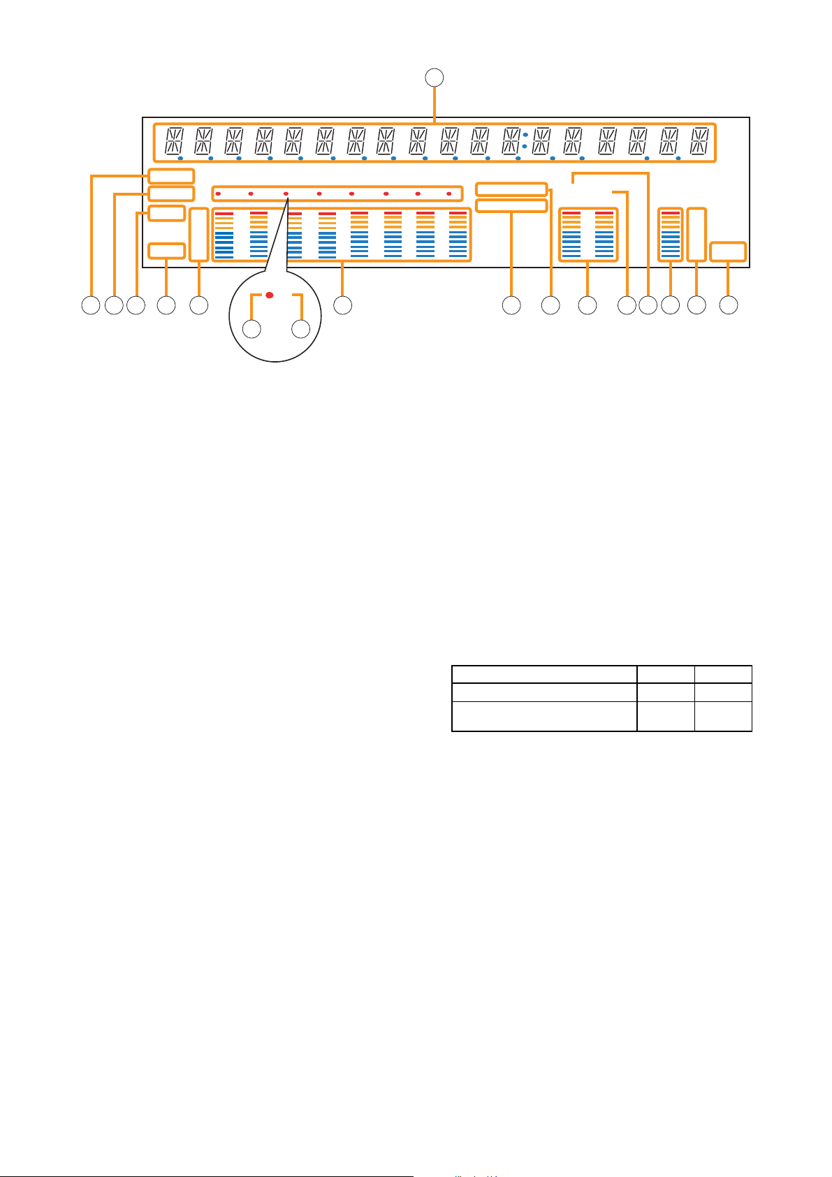
28
[Fluorescent Display]
SX-2100AO
21. Text Display Area
Displays the menu screen information when the
corresponding function key is pressed.
22. COM Indicator [COM]
Flashes to indicate a communications error.
23. Fault Indicator [FAULT]
Flashes when a system failure, incorrect system
configuration*1or communications error is
detected. This indicator continues to flash until
failure conditions return to normal.
*
1
When the system or module configuration
differs from the contents set by the SX-2000
Setting Software.
24. Output Level Meter Fader Indicator [FADER]
Lights when the output level meter indicates the
sound volume set using the SX-2000 Setting
Software or output volume control.
25. Output Level Meter Level Indicator [LEVEL]
Lights when the output level meter indicates the
level being output from the SX-2100AO.
26. Output Level Meter Scale
27. Output Indicator
The output channel to be monitored lights red.
In the case of speaker line initial setting, this
indicator lights when the channel is selected.
(For the speaker line initial setting, see p. 130.)
28. Output ON/OFF Indicator
Indicates the unit's operating status when the
corresponding channel key is pressed.
The indicator state differs depending on the
function assigned to each channel key as
follows.
*2The indicator state is "Unlit" when the output volume is muted.
In the case of speaker line initial setting, all
channel numbers 1 – 8 light up.
(For the speaker line initial setting, see p. 130.)
29. Output Level Meter
Indicates the actual level, a set volume value, or
speaker line open/short status on each output
channel.
30. Emergency Indicator [EMERGENCY]
Lights when the SX-2000 system is in an
emergency condition.
31. Key Lock Indicator [KEY LOCK]
Lights when the output volume controls and
channel keys are locked. (See p. 143, "Key Lock
Settings and Cancellation.")
Notes
• A timer-activated light shutoff function can be set for the fluorescent display using the SX-2000 Setting
Software. (See the separate Setting Software Instructions, "Basic Settings.")
When the light shutoff function has been set, if the SX-2100AO is not operated for 5 minutes or more, the
fluorescent display's light goes off and the standby indicator (11) begins to flash. Pressing any keys other
than the function keys on the front panel resets the screen display.
• Normally, the fluorescent display's light goes off at the time of the power failure.
• While the SX-2000 system is in an emergency condition, the fluorescent display's light does not go off even
if the power fails.
Function assigned to the channel key When ON When OFF
Output ON/OFF Lights*
2
Unlit
General-purpose pattern broadcast's Flashes Lights
activation and termination
21
COM
FAULT
FADER
LEVEL LEVEL
12 345678
OL
0
–10
–20
–30
–40
33
22 23 24 25 26 29 30 31 32 33 34
KEYLOCK
EMERGENCY
12
OL
0
–10
–20
–30
–40
35 36 37
27 28
Page 29
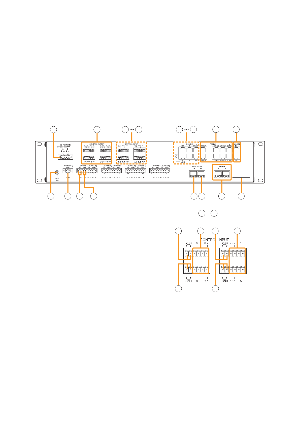
29
[Rear]
38. DC Power Input Terminal [DC POWER IN]
Connect an optional DC power supply unit to this
terminal. Select the DC power supply source with
consideration given to the current power
consumption of the system the SX-2100AO is to
be connected to. When not using a redundant
power system*, connect the [+] terminal of input
A to the [+] terminal of input B, and the [–]
terminal of input A to the [–] terminal of input B.
(
Refer to the Instruction Manual attached to the
VX-2000DS.
)
* A method of connecting separate power
sources to each power input or connecting the
commercial power supply and backup power
supply separately to each power input to
prevent the system from going down when a
cable is broken or power fails.
39. Control Output Terminals
[CONTROL OUTPUT 1 – 8]
Relay make contact outputs. Each contact
capacity is rated at 40 V DC for withstand
voltage, and 2 mA – 300 mA for control current.
These terminals are controlled by the SX-2000
Setting Software. (See the separate Setting
Software Instructions, "Pattern Settings.")
Note
With this Setting Software, these control
terminals can also be set to control external
attenuators. (See the Setting Software
Instructions, "System Settings.")
40. Power Feed Jumper 2 [VCC]
The supplied removable terminal plug is
equipped with a jumper.
When the jumper is attached, the circuits of
control inputs 3, 4, 7, and 8 are powered from
inside the SX-2100AO.
Removing the jumper disconnects this internal
power supply and thus requires that power be
supplied externally to the circuit. (See "Operation
of Power Feed Jumper and Isolation Jumper" on
the next page.)
SX-2100AO
32. Local Audio Input Level Meter
Indicates each level of signals applied to the
Local audio inputs 1 and 2 while the Local audio
control inputs 1 and 2 are activated, respectively.
33. Control Output Unit Connection Indicator [2]
Indicates "2" when the SX-2000CO is connected
to the SX-2100AO.
34. Control Input Unit Connection Indicator [1]
Indicates "1" when the SX-2000CI is connected
to the SX-2100AO.
35. Monitor Level Meter
Indicates the sound volume level of the output
channel being monitored.
36. Monitor Level Meter Scale
Lights when the monitor ON/OFF key (15) is set
to ON.
37. Monitor ON/OFF Indicator [LEVEL]
Lights when the monitor ON/OFF key (15) is set
to ON.
38 39 40 44 45
49
50 51
52 53 54 55 56 57 58 59
[Enlarged view of – above]
40
40
44
41 41
42
43 44
Page 30
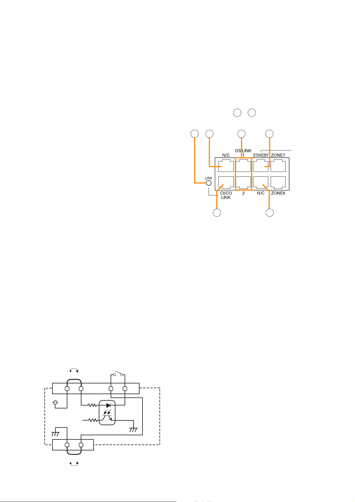
41. Control Input Terminals
[CONTROL INPUT 1 – 8]
Photo coupler inputs. A current of approximately
2 mA flows when shorted, and the voltage
becomes under 40 V DC when opened. The
input of 100 msec or greater is required to
operate. These contact inputs can be isolated
from the SX-2100AO unit by cutting power feed
jumpers 1 (42) and 2 (40) and isolation jumpers
1 (44) and 2 (43). Each contact input when
isolated is 40 V DC for maximum applied voltage
and approximately 2 mA for the loop current.
Since each terminal is equipped with a current
limiter employing constant current circuitry, there
is no need to limit the current on the external
equipment side. The [–] terminals of 1, 2, 5, and
6 are common, while those of 3, 4, 7, and 8 are
common.
Use the SX-2000 Setting Software to assign
functions to these terminals. (See the separate
Setting Software Instructions, "Event Settings.")
42. Power Feed Jumper 1 [VCC]
The supplied removable terminal plug is
equipped with a jumper. When the jumper is
attached, the circuits of control inputs 1, 2, 5, and
6 are powered from inside the SX-2100AO.
Removing the jumper disconnects this internal
power supply and thus requires that power be
supplied externally to the circuit. (See "Operation
of Power Feed Jumper and Isolation Jumper"
shown below.)
43. Isolation Jumper 2 [GND]
The supplied removable terminal plug is
equipped with a jumper. When the jumper is
attached, the [–] terminals of control inputs 3, 4,
7, and 8 are connected to the internal power
supply. Removing the jumper disconnects and
isolates these [–] terminals from this unit. (See
"Operation of Power Feed Jumper and Isolation
Jumper" shown below.)
44.Isolation Jumper 1 [GND]
The supplied removable terminal plug is
equipped with a jumper.
When the jumper is attached, the [–] terminals of
control inputs 1, 2, 5, and 6 are connected to the
internal power supply.
Removing the jumper disconnects and isolates
these [–] terminals from this unit. (See
"Operation of Power Feed Jumper and Isolation
Jumper" shown below.)
45. CI/CO Link Indicator [LINK] (Green)
Lights when the SX-2000CI or the SX-2000CO is
connected.
46. Unused Terminals [N/C]
These terminals are not used.
47. DS Link Terminals [DS LINK 1/2]
Connect either terminal to the DS-SF Link
terminal of the VX-2000DS.
48. Standby Amplifier Audio Output Terminal
[PA LINK STANDBY]
Connect this terminal to the VP-200VX Power
Amplifier Input Module built into a standby
amplifier*.
* Use the VP-2064, VP-2122, VP-2241, or VP-
2421.
49. CI/CO Link Terminal [CI/CO LINK]
Connect this terminal to the CI/CO Link Data
Terminal of the SX-2000CI or SX-2000CO.
50. Audio Output Terminals
[PA LINK ZONE 1 – 8]
Connect these terminals to the VP-200VX Power
Amplifier Input Modules used for zone output.
30
SX-2100AO
[Operation of Power Feed Jumper and
Isolation Jumper]
[Enlarged view of – on p. 29]
454546
49
49
47 48
46
VCC
Power feed jumper
Control input
-
Photo coupler
+
Internal circuit
Isolation jumper
GND
Page 31

51. Local Audio Control Input Terminals
[LOCAL AUDIO IN 1/IN 2]
Audio signals fed to these terminals are
broadcast to only the zones that this unit covers.
Each terminal is equipped with a control input,
which allows local broadcasts to be made.
It is possible to isolate the control input from this
unit by changing the internal jumper setting. (See
p. 61 for details.)
Input "IN1" has a higher priority than Input "IN2."
If the control input terminal of "IN1" is activated
while broadcast is made through the "IN2," the
broadcast is interrupted and changed to the
broadcast through the "IN1."
The Local input has a lower priority than the
BGM or general-purpose sound sources.
Activating the emergency broadcasts to a part of
zones where local broadcasts are currently in
progress causes all local broadcasts to
terminate.
52. Functional Earth Terminal [SIGNAL GND]
Hum noise may be generated when external
equipment is connected to the unit. Connecting
this terminal to the functional earth terminal of
the external equipment may reduce the hum
noise.
Note: This terminal is not for protective earth.
53. Standby Amplifier Input Terminal
[STANDBY AMP]
Connect this terminal to the speaker output
terminal of the standby amplifier*
1
.
*
1
Use the VP-2064, VP-2122, VP-2241, or VP-
2421.
54. Speaker Connection Terminals
[ZONE 1 – 8 SP]
Connect these terminals to speakers.
55. Amplifier Input Terminals [ZONE 1 – 8 AMP]
Connect these terminals to the speaker output
terminals of the power amplifiers for zone output.
56. Analog Link Output Terminal
[ANALOG LINK OUT]
Connect this terminal to the analog link input
terminal of the SX-2000AI, SX-2100AI, SX2000AO, or SX-2100AO.
57. Analog Link Input Terminal
[ANALOG LINK IN]
Connect this terminal to the analog link output
terminal of the SX-2000SM, SX-2000AI, SX2100AI, SX-2000AO, or SX-2100AO.
58. SX Link Terminals [SX LINK A/B]
Use switching hubs to connect between the SX
link terminals of the SX-2000SM, SX-2000AI,
SX-2100AI, SX-2000AO, and SX-2100AO.
Connect each of the SX Links A and B to the
same switching hub*
2
, or to different switching
hubs*2that have been cascade connected.
Notes
• Be sure to connect both terminals of A and B.
• After connection completion, press the Reset
key to reactivate the SX-2100AO.
*
2
Contact your TOA dealer for more information
on switching hubs.
59. MAC Address
MAC address to be used for SX link connection.
31
SX-2100AO
34
Function LED On LED Off
3. RESET input Resetting Normal
4. Not used
1 2
Function LED On LED Off
1. Not used
2. OUT connection confirmation Connected Unconnected
1 234
Function
1. B operation in progress
indication
2. B connection confirmation Connected Unconnected
3. A operation in progress
indication
4. A connection confirmation Connected Unconnected
LED On/Flashing
Operating Not operating
Operating Not operating
LED Off
Page 32

32
1.6. SX-2000CI Control Input Unit
[Front]
1. Control Input Indicators
[CONTROL INPUT 1 – 32] (Green)
Light when the corresponding control inputs are
turned ON.
2. Power Indicator [POWER] (Blue)
Lights when the power is switched on.
3. CPU OFF Indicator [CPU OFF] (Red)
Lights while the general urgency all-call (CPU
OFF state) is being made (p. 68).
4. FAULT Indicator [FAULT] (Yellow)
Lights while the general urgency all-call is being
made (p. 68) or when communications to the SX2000AO or SX-2100AO are interrupted for 5
seconds or more.
Flashes when a failure is detected in the system.
5. USB Port [USB]
This port is not used.
6. RUN Indicator [RUN] (Green)
Normally flashes continuously.
Goes off while the general urgency all-call is being
made (p. 68).
7. ID Switch [ID NUMBER]
This switch is not used.
Always set to "0."
Note
This switch is set to "0" by default.
8. Reset Key [RESET]
Pressing this key resets the SX-2000CI.
9. DIP Switch [SETTING]
These switches are not used.
Note
Switches 1 – 8 are set to the OFF position by
default.
SX-2000CI
Protective cover
Inside of the protective cover
USB RUN
ID NUMBER
9
8
7
6
5
4
3
2
0
1
5 6 7 8 9
192103114125136147158
RESET
A
B
C
D
E
F
2
POWER
CPU OFF
FAULT
CONTROL INPUT UNIT SX-2000CI
16
1
172518261927202821292230233124
32
CONTROL INPUT
3 4
SETTINGON
Page 33

33
SX-2000CI
[Rear]
10. Functional Earth Terminal [SIGNAL GND]
Hum noise may be generated when external
equipment is connected to the unit. Connecting
this terminal to the functional earth terminal of
the external equipment may reduce the hum
noise.
Note: This terminal is not for protective earth.
11. DC Power Input Terminal [DC POWER IN]
Connect an optional DC power supply unit to this
terminal. Select the DC power supply source with
consideration given to the current power
consumption of the system the SX-2000CI is to
be connected to. When not using a redundant
power system*, connect the [+] terminal of input
A to the [+] terminal of input B, and the [–]
terminal of input A to the [–] terminal of input B.
(
Refer to the Instruction Manual attached to the
VX-2000DS.
)
* A method of connecting separate power
sources to each power input or connecting the
commercial power supply and backup power
supply separately to each power input to
prevent the system from going down when a
cable is broken or power fails.
12. 24 V DC Output Terminal [DC 24 V OUT]
This terminal supplies 24 V DC, max. 100 mA to
connected external equipment.
13. Control Input Terminals
[CONTROL INPUT 1 – 32]
Photo coupler inputs. A current of approximately
2 mA flows when shorted, and the voltage
becomes approximately 24 V DC when opened.
Functions can be assigned to these terminals
using the SX-2000 Setting Software. (See the
separate Setting Software Instructions, "Event
Settings.")
14. CI/CO Link Through Switch [ON/OFF]
Set to ON when using the CI/CO Link Through
Terminal (15). (Factory-preset: OFF)
15. CI/CO Link Through Terminal
[CI/CO LINK THROUGH]
Connect this terminal to the CI/CO Link Data
Terminal of the SX-2000CO.
Refer to the table below for the indicators'
functions and status.
16. CI/CO Link Data Terminal [CI/CO LINK DATA]
Connect this terminal to the CI/CO Link Terminal
of the SX-2000AO or SX-2100AO, or CI/CO Link
Through Terminal of the SX-2000CO.
Refer to the table below for the indicators'
functions and status.
[Indicators' functions and status of the CI/CO Link Through/Data terminals]
10
12 14 15 1613
11
DC 24V OUT
MAX. 0.1A
1718192021222324
CONTROL
INPUT
2526272829303132
12345678
910111213141516
ONOFF
CI/CO LINK
THROUGH
DATA
CI/CO LINK
THROUGH
1 234
1. CI/CO LINK status Communication start Communication stop
2.
3. CI/CO LINK status Communication start Communication stop
4. CI/CO LINK connection
confirmation
DATA
Functions LED On or Flashing (green) LED Off LED On (orange)
Unconnected Connected
Page 34

34
1.7. SX-2000CO Control Output Unit
[Front]
1. Control Output Indicators
[CONTROL OUTPUT 1 – 32] (Green)
Light when the corresponding control outputs are
turned ON.
All indicators are factory-preset to go off because
all control outputs are turned off when the general
urgency all-call is made. By changing the internal
DIP switch settings for the desired control outputs,
the corresponding outputs can be turned ON,
making the indicators light up when the general
urgency all-call is made. (For details, see p. 62.)
2. Power Indicator [POWER] (Blue)
Lights when the power is switched on.
3. CPU OFF Indicator [CPU OFF] (Red)
Lights while the general urgency all-call (CPU
OFF state) is being made (p. 68).
4. FAULT Indicator [FAULT] (Yellow)
Lights while general urgency all-call is being made
(p. 68) or when communications to the SX-
2000AO or SX-2100AO are interrupted for 5
seconds or more. Flashes when a failure is
detected in the system.
5. USB Port [USB]
This port is not used.
6. RUN Indicator [RUN] (Green)
Normally flashes continuously.
Goes off while the general urgency all-call is being
made (p. 68).
7. ID Switch [ID NUMBER]
This switch is not used.
Always set to "1."
Note
This switch is set to "1" by default.
8. Reset Key [RESET]
Pressing this key resets the SX-2000CO.
9. DIP Switch [SETTING]
These switches are not used.
Note
Switches 1 – 8 are set to the OFF position by
default.
SX-2000CO
Protective cover
Inside of the protective cover
USB RUN
ID NUMBER
8
7
6
5
4
3
2
1
5 6 7 8 9
192103114125136147158
9
A
B
C
D
E
F
0
1
172518261927202821292230233124
16
CONTROL OUTPUT
RESET
SETTINGON
32
CONTROL OUTPUT UNIT SX-2000CO
3 4
2
POWER
CPU OFF
FAULT
Page 35

35
[Rear]
10. Functional Earth Terminal [SIGNAL GND]
Hum noise may be generated when external
equipment is connected to the unit.
Connecting this terminal to the functional earth
terminal of the external equipment may reduce
the hum noise.
Note
This terminal is not for protective earth.
11. DC Power Input Terminal [DC POWER IN]
Connect an optional DC power supply unit to this
terminal.
Select the DC power supply source with
consideration given to the current power
consumption of the system the SX-2000CO is to
be connected to. When not using a redundant
power system*, connect the [+] terminal of input
A to the [+] terminal of input B, and the [–]
terminal of input A to the [–] terminal of input B.
(
Refer to the Instruction Manual attached to the
VX-2000DS.
)
* A method of connecting separate power
sources to each power input or connecting the
commercial power supply and backup power
supply separately to each power input to
prevent the system from going down when a
cable is broken or power fails.
12. Control Output Terminals
[CONTROL OUTPUT 1 – 32]
Relay make contact outputs. Each contact
capacity is rated at 40 V DC for withstand
voltage, and 2 mA – 300 mA for control current.
These terminals are controlled by the SX-2000
Setting Software. (See the separate Setting
Software Instructions, "Pattern Settings.")
13. CI/CO Link Through Switch [ON/OFF]
Set to ON when using the CI/CO Link Through
Terminal (14). (Factory-preset: OFF)
14. CI/CO Link Through Terminal
[CI/CO LINK THROUGH]
Connect this terminal to the CI/CO Link Data
Terminal of the SX-2000CI.
Refer to the table below for the indicators'
functions and status.
15. CI/CO Link Data Terminal [CI/CO LINK DATA]
Connect this terminal to the CI/CO Link Terminal
of the SX-2000AO or SX-2100AO, or CI/CO Link
Through Terminal of the SX-2000CI.
Refer to the table below for the indicators'
functions and status.
SX-2000CO
[Indicators' functions and status of the CI/CO Link Through/Data terminals]
10
11
14 151312
1718192021222324
12345678
CONTROL
OUTPUT
CNCNO
CI/CO LINK
THROUGH
DATA
ONOFF
9101112131415162526272829303132
CI/CO LINK
THROUGH
1 234
1. CI/CO LINK status Communication start Communication stop
2.
3. CI/CO LINK status Communication start Communication stop
4. CI/CO LINK connection
confirmation
DATA
Functions LED On or Flashing (green) LED Off LED On (orange)
Unconnected Connected
Page 36

36
1.8. RM-200SF Fireman's Microphone
[Top]
1. Power Indicator (Green)
Lights when the power is turned on.
2. Emergency Key
Assign emergency activation function to this key
using the SX-2000 Setting Software.
Lights when the SX-2000 system is in an
emergency condition.
3. Monitor Speaker
Not used.
4. Monitor Speaker Volume Control [SP]
Not used.
5. Microphone Volume Control [MIC]
Adjusts the input sensitivity of the Hand-held
Microphone.
6. Microphone Hanger
Used to hold the unit's Hand-held Microphone.
7. CPU Switch [CPU ON/OFF]
Normally set to ON. (Factory-preset: ON)
Setting this switch to OFF in combination with the
DIP switch setting (20) on the bottom surface
allows the general urgency all-call to be made
using a hand-held microphone by way of analog
transmission not via the CPU control.
8. Indication Label Insert Slot
The label can be printed using the SX-2000
Setting Software. (See the separate Setting
Software Instructions, "Printing Labels for
Remote Microphones.")
9. Failure Indicator (Yellow/Red)
Flashes yellow if some problem within the
system is detected.
This indicator will light yellow if the signal to the
SX-2000AI or SX-2100AI to which the RM200SF is connected is interrupted for 5 seconds
or more.
Lights red when the unit is placed in reset state
by pressing the Reset Switch (11).
10. CPU Indicator (Red)
Lights red when any one of the CPU switches on
the RM-200SFs connected within the system is
set to OFF or when the general urgency all-call is
being made by any one of the RM-200SAs
connected within the system.
11. Reset Switch
Used to reactivate the RM-200SF unit.
Holding down both this switch and the R3 key of
the Function keys (14) for 2 seconds or more
causes the Failure Indicator (9) to light red,
placing the RM-200SF in reset state.
RM-200SF
RM-200SF
FIREMAN'S MICROPHONE
1
2
3
4
5
MIC SP CPU
OFF ON
6
7 8
9
10
[Hand-held microphone]
11
12
13
18
14
15
17
16
Page 37

37
[Side]
12. Status Indicators (Red/Yellow/Green)
Light, flash, or go off depending on the current
operation state of function keys, failure state or
emergency state. (See the separate Operating
Instructions, "RM-200SF Fireman's Microphone"
and "Operation.")
13. Selection Indicators (Green)
Light or go off depending on the current
operation state of function keys. (See the
separate Operating Instructions, "RM-200SF
Fireman's Microphone" and "Operation.")
14. Function Keys (R1 – R3)
Positioned in top-down order (R1, R2, R3).
Pressing a specific function key executes the
function that has been assigned to that key by
the SX-2000 Setting Software.
Assignment of functions to specific keys is done
using the SX-2000 Setting Software. (See the
separate Setting Software Instructions, "Event
Settings.")
15. Microphone Indicator (Green)
Lights or goes off depending on the current
operation state of the Talk key.
16. Broadcast Status Indicator
(Yellow/Green)
Lights, flashes, or goes off depending on the
current operation state of the Talk key.
17. Talk Key
Press this key to broadcast a voice announcement.
It must be pressed continuously for the duration
of the broadcast.
18. Microphone
Used for voice announcements.
19. RM-210 Connection Terminal [EXTENSION]
Connect the RM-210 Remote Microphone
Extension unit to this terminal.
(See p. 79 and p. 82.)
RM-200SF
19
EXTENSION
Page 38

38
[Wall mount bracket unit (Accessory)]
[Bottom]
20. DIP Switch [DIP SWITCH]
Used for setting the RM-200SF unit.
• Switches 1 – 3 [UNIT ID]
Set the RM-200SF's device number (ID
number). (See p. 64.)
• Switch 4 [COMMUNICATION]
Sets the RM communication function.
(See p. 69.)
• Switch 5 [LEVEL METER]
Changes a broadcast status indicator (12) into
an output signal level indicator. (See p. 66.)
• Switch 6 [CPU OFF]
Sets whether the CPU OFF function (general
urgency all-call) is enabled or disabled.
(See p. 68.)
• Switch 7
Not used. Normally set to OFF.
• Switch 8 [TERMINATION]
Sets the termination of the RM communication
line (Control communication lines between the
SX-2000 system and the RM-200SF). Normally
set to ON.
Note
By default, DIP switches 1 – 5 and 7 are set to
OFF, and DIP switches 6 and 8 to ON.
21. USB Terminal
Not used.
22. Extension Connector
Connect this connector to the extension connector
(23) of the Wall Mount Bracket Unit (accessory).
(See p. 78.)
23. Extension Connector
Connect the cable extending from the RM-200SF
to this connector. (See p. 78.)
24. Screw Terminal Block
• Audio Monitor Line [MONITOR IN]
Connect the audio monitor input line from the
SX-2000 system to the RM-200SF.
• RM Communication Line [DATA]
Connect the control communication line
between the SX-2000 system and the RM200SF.
• Audio Output Line [AUDIO OUT]
Connect the audio signal output line from the
RM-200SF to the SX-2000 system.
• DC Power Input [DC IN 24 V]
Used to supply DC power from the SX-2000
system to the RM-200SF.
• Shield [SHIELD]
Used for the control line through which the SX2000 system confirms the RM-200SF's
connection.
Be sure to connect at least one of two terminals
to the SX-2000 system.
RM-200SF
DIP SWITCH
OnOff
1
UNIT ID
2
3
COMMUNICATION
4
LEVEL METER
5
CPU OFF
6
7
TERMINATION
8
20 21 22
24
23
Page 39

39
1.9. RM-200SA Remote Microphone
[Top]
1. Microphone
Used for voice announcements.
2. Power Indicator (Green)
Lights when the power is turned on.
3. Failure Indicator (Yellow/Red)
Flashes yellow if some problem within the system
is detected.
This indicator will light yellow if the signal to the
SX-2000AI or SX-2100AI to which the RM-200SA
is connected is interrupted for 5 seconds or more.
This indicator will light red while the general
urgency all-call is being made (p. 68) or the RM200SA is in the reset process.
4. Emergency Indicator (Red)
Lights when the SX-2000 system is in an
emergency condition.
5. Emergency/General Urgency All-call Key
(Covered)
When the Emergency Broadcast Pattern Start
function has been assigned to this key by the SX2000 Setting Software, pressing it activates the
emergency broadcast from the SX-2000 system.
Independently of settings made by the SX-2000
Setting Software, holding down this key for 4
seconds or more in combination with DIP switch
(14) setting causes the CPU to be bypassed,
enabling the general urgency all-call to be made
by way of analog transmissions. (See p. 68.)
6. Indication Label Insert Slots
Labels can be printed using the SX-2000 Setting
Software. (See the separate Setting Software
Instructions, "Printing Labels for Remote
Microphones.")
7. Status Indicators (Red/Yellow/Green)
Light, flash, or go off depending on the current
operation state of function keys, failure state or
emergency state. (See the separate Operating
Instructions, "Remote Microphone RM-200SA,
Remote Microphone Extension RM-210" and
"Operation.")
8. Selection Indicators (Green)
Light or go off depending on the current operation
state of function keys.
(See the separate Operating Instructions,
"Remote Microphone RM-200SA, Remote
Microphone Extension RM-210" and "Operation.")
9. Function Keys (R1 – R10)
Positioned in top-down order (R1, R2 ... R10).
Pressing a specific function key executes the
function that has been assigned to that key by
the SX-2000 Setting Software.
Assignment of functions to specific keys is done
using the SX-2000 Setting Software. (See the
separate Setting Software Instructions, "Event
Settings.")
RM-200SA
2 4 6 7 9
3 5
8
6
1
7
8
RM-200SA
10
11 12 13
Page 40

40
10. Talk Key
Press this key to broadcast a voice announcement.
If the Talk key is set to "PTT" ("press-to-talk")
mode, then it must be pressed continuously for
the duration of the broadcast.
If the Talk key is set to "Lock" mode, then it must
be pressed once to turn the microphone on at
the beginning of a broadcast, then pressed again
to turn the microphone off once the broadcast is
finished.
The microphone can also be set to sound a
chime at the beginning and/or end of each
broadcast.
The Talk key mode ("PTT" or "Lock") and the
chime function are set using the SX-2000 Setting
Software. The RM-200SA of which "Type" is set
to "General/Emergency" on the SX-2000 Setting
software is fixed to "PTT" mode for the Talk key
with no chime activation. (See the separate
Setting Software Instructions, "System Settings.")
11. Function Keys (L1 – L3)
Positioned in top-down order (L1, L2, L3).
These keys operate in the same manner as the
Function keys (R1 – R3) (No. 9).
12. Broadcast Status Indicator
(Yellow/Green)
Lights, flashes, or goes off depending on the
current operation state of the Talk key.
13. Microphone Indicator (Green)
Lights or goes off depending on the current
operation state of the Talk key.
Flashes while the chime is being activated.
[Side]
14. DIP Switch
Used for setting the RM-200SA unit.
• Switches 1 – 3
Sets the RM-200SA's device number (ID
number). (See p. 64.)
• Switch 4
Changes a broadcast status indicator (12) into
an output signal level indicator. (See p. 66.)
• Switch 5
Sets whether the CPU OFF function (general
urgency all-call) is enabled or disabled.
(See p. 68.)
• Switch 6
Sets the RM communication function.
(See p. 69.)
Note
By default, DIP switches 1 – 4 and 6 are set to
OFF and DIP switch 5 to ON.
15. RM-210 Connection Terminal [EXTENSION]
Directly connect the RM-210 Remote Microphone
Extension unit to this terminal.
(See p. 79 and p. 82.)
RM-200SA
14
15
Page 41

41
[Rear]
16. Power Input Terminal [DC POWER IN]
Connect an optional AD-246 AC adapter to this
terminal when extending cable length. Power is
usually supplied to the RM-200SA and RM-210
from the SX-200RM Remote Microphone
Interface Module. (See p. 103.)
17. USB Terminal [USB]
Not used.
18. RM Link Terminal [RM LINK]
Used to connect an SX-200RM Remote
Microphone Interface Module via a STP
Category 5 cable.
19. Speaker Volume Control [SP]
Adjusts the volume of the built-in speaker.
20. Microphone Volume Control [MIC]
Adjusts the volume of the microphone (1) and
the external microphone connected via the
external microphone input terminal (21).
21. External Microphone Input Terminal
[EXTERNAL MIC IN]
Connect an optional external microphone*1 to this
terminal.
Jumper settings on the circuit board must be
changed depending on the input sources. (See
p. 70.)
Specifications: –40 dB*2, 2.2 kΩ, unbalanced,
mini-jack, and phantom power.
*1The WH-4000A, YP-M101, or YP-M301 can be
used for the external microphone.
*20 dB = 1 V
RM-200SA
16 18 1917
20
21
Page 42

42
1.10. RM-210 Remote Microphone Extension
Note
Up to 5 RM-210 Remote Microphone Extensions can be connected to each RM-200SF Fireman's Microphone.
Up to 4 RM-210 Remote Microphone Extensions can be connected to each RM-200SA Remote Microphone.
[Top]
1. Indication Label Insert Slot
The label can be printed using the SX-2000
Setting Software. (See the separate Setting
Software Instructions, "Printing Labels for Remote
Microphones.")
2. Status Indicators (Red/Yellow/Green)
Light, flash, or go off depending on the current
operation state of function keys.
3. Selection Indicators (Green)
Light or go off depending on the current operation
state of function keys
4. Function Keys (1 – 10)
Positioned in top-down order (1, 2 ... 10). Pressing
a specific function key executes the function that
has been assigned to that key by the SX-2000
Setting Software.
Assignment of functions to specific keys is done
using the SX-2000 Setting Software. (See the
separate Setting Software Instructions, "RM
Function Key Settings.")
[Side]
5. RM Connection Terminal [EXTENSION]
Connect the RM-200SF, RM-200SA, or other
RM-210 to this terminal. (See p. 79 and p. 82.)
Note
Another same terminal is on the other side.
RM-210
2
3
1
4
5
Page 43

43
1.11. RM-200RJ Terminal Unit
[Front]
1. RM Link Terminal [RM LINK]
Connect to the RM Link terminal of the RM-200SA
or SX-200RM.
2. Power Monitor Switch [ON/OFF]
Set to ON to enable the Power Monitor Indicator.
(Factory-preset: ON)
3. Power Monitor Indicator (Green)
Lights if the source voltage of the DC power input
exceeds the minimum operating voltage of the
RM-200SA when the Power Monitor Switch is set
to ON.
4. Screw Terminal Block
The Screw terminal block and RM link terminal are
internally connected in parallel. Numbers
through indicated beside each terminal
correspond to the pin numbers of the RJ45
connector to be connected to the RM link terminal
(1).
• Audio monitor terminals [MONITOR H/C]
Connect the audio monitor line from the SX-2000
system to the RM-200SA.
• Audio output terminals [AUDIO H/C]
Connect the audio output line from the RM200SA to the SX-2000.
• RM communication terminals [DATA +/–]
Connect the control communication line between
the SX-2000 system and the RM-200SA.
• DC power input terminals [DC 24 V +/–]
Used to supply DC power from the SX-2000
system to the RM-200SA.
• Shield terminals [SHIELD]
Connect the shield wires for noise reduction or
for system control.
Be sure to connect at least one shield wire.
1
1
2
3
4
8
Page 44

44
1.12. Optional Modules
The following modules can be used in the input module slots on the SX-2000AI's and SX-2100AI's rear
panels:
SX-200RM Remote Microphone Interface Module
D-921E, D-921F, D-922E and D-922F Microphone/Line Input Modules
D-936R Stereo Input Module
1.12.1. SX-200RM Remote Microphone Interface Module
1. Gain Control Knobs [GAIN]
Increase the audio level of the RM-200SF or RM-200SA Remote Microphone by up to 12 dB.
2. RM Link Terminals [RM LINK 1/2]
Used to connect the RM-200SF or RM-200SA Remote Microphones. Each terminal can supply up to 1 A
of power to the connected RM-200SF or RM-200SA/210.
Note
The terminal with the RM1 or RM2 status LED lit orange is the one assigned by the SX-2000 Setting
Software. Connect the RM-200SF or RM-200SA to that terminal.
Note
All of the inserted modules cannot be recognized correctly when any module other than listed above is
inserted into the SX-2000AI's or SX-2100AI's module slots.
1 12
FOR SX-2000 SERIES ONLY
1234
Function LED On or Flashing (Green) LED Off LED On (Orange)
1. RM1 connection confirmation
2. RM1 status
3. RM2 connection confirmation
4. RM2 status
Connected
Communication start
Connected
Communication start
Unconnected
Communication stop
Unconnected
Communication stop
Control start
Control start
Page 45

45
1.12.2. D-921E Microphone/Line Input Module
1. Monaural Input Terminals [1, 2]
Electronically-balanced, removable terminal blocks. (H: Hot; C: Cold; E: Ground)
Input sensitivity (–50/–36/–10/+4 dB) and phantom power (+12 V) ON/OFF can be set by the SX-2000
Setting Software.
Note
Be sure to use the supplied removable terminal plugs (3P) for connection.
2. Ground Lift Switches [GND LIFT/NORMAL]
Hum noise may be generated due to ground loops created when the SX-2000 system is connected to
other equipment. Setting the switch to the GND LIFT position cuts the ground loop.
1.12.3. D-921F Microphone/Line Input Module
1. Monaural Input Terminals [1, 2] (XLR-3-31 equivalent)
Electronically-balanced input terminals. (Pin 1: Ground; Pin 2: Hot; Pin 3: Cold)
Use XLR-3-12C or equivalent for connection.
Input sensitivity (–50/–36/–10/+4 dB) and phantom power (+12 V) ON/OFF can
be set by the SX-2000 Setting Software.
2. Ground Lift Switches [GND LIFT/NORMAL]
Hum noise may be generated due to ground loops created when the SX-2000 system is connected to
other equipment. Setting the switch to the GND LIFT position cuts the ground loop.
1 2 1 2
NORMAL
2
E
C
H
GND LIFT
NORMAL
ACCESSORY I.T.E 78CK
model D-921E
1
E
C
H
GND LIFT
MIC/LINE INPUT MODULE [–50 / –36 / –10 / +4 dB]
1 2 1 2
NORMAL
2
GND LIFT
: E
1
NORMAL
: H
2
: C
3
ACCESSORY I.T.E 78CK
2: Hot
3: Cold
1: Ground
1
GND LIFT
MIC/LINE INPUT MODULE [–50 / –36 / –10 / +4 dB] model D-921F
Page 46

46
1.12.4. D-922E Microphone/Line Input Module
1. Monaural Input Terminals [1, 2]
Electronically-balanced, removable terminal blocks. (H: Hot; C: Cold; E: Ground)
Note
Be sure to use the supplied removable terminal plugs (3P) for connection.
2. Input Sensitivity Switches [PHANTOM, GND LIFT, MIC/LINE]
4-pole switches. Enable phantom power (+12V; ON/OFF, enabled only
when set to the MIC position), ground lift and input sensitivity.
Input sensitivity: –36 or –50 dB (MIC mode) / –10 or +4 dB (LINE
mode)
1.12.5. D-922F Microphone/Line Input Module
1. Monaural Input Terminals [1, 2] (XLR-3-31 equivalent)
Electronically-balanced input terminals. (Pin 1: Ground; Pin 2: Hot; Pin 3: Cold)
Use XLR-3-12C or equivalent for connection.
2. Input Sensitivity Switches [PHANTOM, GND LIFT, MIC/LINE]
4-pole switches. Enable phantom power (+12 V; ON/OFF, enabled only
when set to the MIC position), ground lift and input sensitivity.
Input sensitivity: –36 or –50 dB (MIC mode) / –10 or +4 dB (LINE
mode)
1 2 1 2
-36dB(MIC)
+4dB(LINE)
-10dB(LINE)
-50dB(MIC)
2
E
C
H
-36dB(MIC)
+4dB(LINE)
OFF : PHANTOM
LIFT : GND
ON
LINE
MIC
NORMAL
-10dB(LINE)
-50dB(MIC)
ACCESSORY I.T.E 78CK
1
E
C
H
OFF : PHANTOM
LIFT : GND
LINE
ON
MIC/LINE INPUT MODULE model D-922E
MIC
NORMAL
ON
NORMAL
MIC
OFF : PHANTOM
LIFT : GND
LINE
–10 dB (LINE)
–50 dB (MIC)
+ 4 dB (LINE)
–36 dB (MIC)
1 2 1 2
-36dB(MIC)
+4dB(LINE)
-10dB(LINE)
-50dB(MIC)
2
OFF : PHANTOM
LIFT : GND
LINE
ON
MIC
NORMAL
: E
1
-36dB(MIC)
+4dB(LINE)
-10dB(LINE)
: H
: C
2
3
-50dB(MIC)
ACCESSORY I.T.E 78CK
1
OFF : PHANTOM
LIFT : GND
LINE
ON
MIC/LINE INPUT MODULE model D-922F
MIC
NORMAL
ON
NORMAL
MIC
3: Cold
OFF : PHANTOM
LIFT : GND
LINE
–10 dB (LINE)
–50 dB (MIC)
2: Hot
1: Ground
+ 4 dB (LINE)
–36 dB (MIC)
Page 47

47
1.12.6. D-936R Stereo Input Module
1. Monaural Input Terminal 1 [1L/2L/3L/4L]
Unbalanced, RCA jack input terminals.
Input signal level: –10 dB
2. Monaural Input Terminal 2 [1R/2R/3R/4R]
Unbalanced, RCA jack input terminals.
Input signal level: –10 dB
Notes
• This module can only be used in the SX-2000
system for monaural input.
• Make sure that the channels indicated on the
module differ from those set for the SX-2000
system.
1L
1R
2L
2R
3L3R
4L4R
ACCESSORY I.T.E 78CK
model D-936RSTEREO SELECT INPUT MODULE [ –10 dB]
1
2
Page 48

48
1.13. VP-2064, VP-2122, VP-2241, and VP-2421 Power Amplifiers
1. Channel Power Indicators [POWER]
Only the indicator for the input module-mounted
channel lights green when the power is supplied.
• Off: VP-200VX not installed
• Lights green: In-use status
• Lights red: Standby status or DC fuse blowout
2. Overheat Indicator [OVERHEAT]
If the internals of the power amplifier overheat, this
indicator lights yellow and the power amplifier's
operation is stopped.
3. Functional Earth Terminal
Hum noise may be generated when external
equipment is connected to the unit. Connecting
this terminal to the functional earth terminal of the
external equipment may reduce the hum noise.
Note: This terminal is not for protective earth.
4. DC power Input Terminal [DC POWER IN]
Connects to the VX-2000DS Emergency Power
Supply's DC POWER OUT terminal.
5. Output Terminals [PA OUT (SP LINE)]
Connect to the amplifier input terminal of the SX2100AO Audio Output Unit.
The speaker line output voltage can be changed
with an internal modification.
For the modification procedure, see p. 87.
6. Module Slots
Insert the VP-200VX Power Amplifier Input
modules into these slots.
Four different configurations of power amplifiers can be used in the SX-2000 system: 60 W x 4 channels, 120
W x 2 channels, 240 W x1 channel, and 420 W x 1 channel versions. Mount a VP-200VX Power Amplifier
Input module for each channel used.
1.14. VP-200VX Power Amplifier Input Module
1. Input Connector [PA LINK]
This RJ45 connector connects to the SX-2100AO's PA LINK
(ZONE 1 – 8, STANDBY) connector. Output audio signals
are transmitted to the power amplifier, and the power
amplifier's audio monitor signals are returned to the module.
It is also possible to retrieve data regarding power amplifier
overheating status and blown DC fuses.
Insert this module into the Power Amplifier's Input module slot when in use.
[Front]
[Rear]
DC POWER IN
28 V 4.8 A
3
4
CH4
CH
PA OUT (SP LINE)
CH3
CH
CH
5
CH1
CH2
CH
2
POWER AMPLIFIER 4 x 60W VP-2064
CH3 CH1
CH4 CH2
1
POWEROVERHEAT
CH1
CH2
CH3
CH4
6
PA LINK VP-200VX
PA LINK VP-200VX
1
Page 49

49
2. INSTALLATION
2.1. SX-2000SM
2.1.1. System reset enable/disable settings (DIP switch 3 operation)
The entire system can be reactivated by pressing the SX-2000SM's reset key. It is also possible to enable the
entire system to restart through the operation of System Reset button on the SX-2000 Setting software.
Use the SX-2000SM's DIP switch 3 to enable or disable the system reset function with the SX-2000 Setting
software.
Note
For the system reset method with the SX-2000 Setting software, see the separate Setting Software
Instructions, "Resetting the System.")
Step 1. Remove the protective cover on the SX-2000SM's front panel by unscrewing it with a Phillips
screwdriver.
Step 2. Perform DIP switch setting.
2-1. When enabling system reset
Set DIP switch 3 to OFF.
Operation with the System Reset button on
the SX-2000 Setting software is enabled.
2-2. When disabling system reset
Set DIP switch 3 to ON.
Operation with the System Reset button on
the SX-2000 Setting software is disabled.
Step 3. Replace the protective cover.
Note: DIP switch 3 is set to the OFF position
by default.
Inside of the protective cover
Protective cover
Screw
DIP switchReset key
ON
12345678
ON
12345678
Page 50

50
2.1.2. Failure reset operation method settings (DIP switch 4 operation)
One of the following 2 modes can be selected with the SX-2000SM's DIP switch 4 to determine the operation
method of the SX-2000SM’s front-mounted FAULT RESET key and rear-mounted RES terminals of the Date
input terminals.
One touch mode: Pressing the key once or shorting the terminals once executes the
failure reset.
Accidental operation prevention mode: Performing special operation executes the failure reset.
Note
For the detailed description of the operation method, see the separate Operating Instructions, "Detecting
Fault."
Step 1. Remove the protective cover on the SX-2000SM's front panel by unscrewing it with a Phillips
screwdriver.
Step 2. Perform DIP switch setting.
2-1. When selecting one touch mode
Set DIP switch 4 to OFF.
2-2. When selecting accidental operation prevention mode
Set DIP switch 4 to ON.
Step 3. Replace the protective cover.
Note: DIP switch 4 is set to the OFF position
by default.
Inside of the protective cover
Protective cover
Screw
DIP switch
ON
12345678
ON
12345678
Page 51

51
2.2.1. Module installation
Notes
• Make sure that the power is switched OFF before attaching or detaching modules.
• To avoid failures due to static electricity, do not touch the parts on the module circuit board.
• Ensure that the module is installed and secured with screws in the correct position.
• Cover idle slots with the blank panels attached to the SX-2000AI and SX-2100AI as shipped by the factory.
• Two silver slotted screws at the left and right sides of the front panel are handles used for module
detachment. Never rotate them because they do not function as screws.
The following figure shows an example of how the SX-200RM Remote Microphone Interface Module can be
mounted in the SX-2100AI unit.
Step 1. Remove the blank panels attached to the SX-2000AI's or 2100AI's slots.
Note
Save the removed screws for use in Step 2.
Step 2. Mount the module.
Insert the module and fix it in place using the screws (Machine screws M3 x 6) removed in Step 1.
Usable modules are as follows:
• SX-200RM (Remote Microphone Interface Module)
• D-921F (Microphone/Line Input Module)
• D-922F (Microphone/Line Input Module)
• D-921E (Microphone/Line Input Module)
• D-922E (Microphone/Line Input Module)
• D-936R (Stereo Input Module)
Note
Do not use any modules other than those listed above.
2.2. SX-2000AI and SX-2100AI
SX-2100AI
Module
2
Handle
Machine screw M3 x 6
(screw removed in Step 1)
1
Blank panel
Page 52

52
2.2.2. Setting the device number
Notes
• When setting the device number for multiple SX-2000AI and SX-2100AI units, assign different numbers to
each unit. The device number that can be used must not exceed the actual number of SX-2000AI and SX2100AI units set using the SX-2000 Setting Software.
• If a device number is duplicated, then the SX-2000AI and SX-2100AI units assigned that number cannot be
controlled by the SX-2000 system.
Step 1. Remove the protective cover on the SX-2000AI's or SX-2100AI's front panel by unscrewing it with a
Phillips screwdriver.
Step 2. Set the ID switches.
Note: The device number is set to No. 1 by default.
Step 3. Press the Reset key to reactivate the SX-2000AI or SX-2100AI.
Note
Reactivating the SX-2000AI or SX-2100AI stops broadcasts being made via that SX-2000AI or SX2100AI unit.
Step 4. Replace the protective cover.
Inside of the protective cover
Protective cover
1
1
0
0
2
2
F
F
3
3
E
4
4
D
5
5
C
6
6
B
7
7
A
8
8
9
9
Screw
E
D
C
B
A
ID switches Reset key
ID switch
Arrowhead
Device number
ID NUMBER
AB
A
01234567
B
0
12345678
Page 53

53
2.2.3. Changing the type of control outputs (SX-2100AI only)
This change should only be performed by a qualified professional
electrician. If users open the unit case or modify the unit, this may
cause fire or electric shock.
WARNING
All the contact outputs are of normally open type when shipped from the factory.
Each output can be converted into normally closed type by changing the jumper setting on the CIO circuit
board.
Notes
• Turn off the power before starting this work.
• To avoid damage from static electricity, never touch the terminals themselves or any of the parts on the
circuit board.
Step 1. Detach the SX-2100AI's top panel.
Note
Note the specific shapes of the different screws.
Top panel: M3 x 6 flat head machine screw (2 pieces)
Side panel: M3 x 6 binding head machine screw (4 pieces)
SX-2100AI
Top panel
CIO circuit board
Page 54

54
Step 2. Change the jumper settings on the CIO circuit board.
Step 3. Replace the top panel.
Note
In this event, note the specific shapes of the different screws. (See Step 1.)
The numbers at the jumper connectors below correspond to
the control output terminal numbers.
16 14 12 10
8642
15 13 11 9
7531
SX-2100AI
CIO circuit board
Jumper position for the
normally open output
(factory-preset)
Jumper position for the
normally closed output
NO
NO
Rear panel side
NC
7
7
NC
C-OUT 7
Note
This figure shows an example when
the control output 7 is changed into
C-OUT 7
the normally closed type.
Page 55

55
2.3. SX-2000AO and SX-2100AO
2.3.1. Setting the device number
Notes
• When setting the device number for multiple SX-2000AO and SX-2100AO units, assign different numbers to
each unit. The device number that can be used must not exceed the actual number of SX-2000AO and SX2100AO units set using the SX-2000 Setting Software.
• If a device number is duplicated, then the SX-2000AO and SX-2100AO units assigned that number cannot
be controlled by the SX-2000 system.
Step 1. Remove the protective cover on the SX-2000AO's or SX-2100AO's front panel by unscrewing it with a
Phillips screwdriver.
Step 2. Set the ID switches.
Note: The device number is set to No. 1 by default.
Step 3. Press the Reset key to reactivate the SX-2000AO or SX-2100AO.
Note
Reactivating the SX-2000AO or SX-2100AO stops broadcasts being made via that SX-2000AO or
SX-2100AO unit.
Step 4. Replace the protective cover.
Inside of the protective cover
Protective cover
1
1
0
0
2
2
F
F
3
3
E
4
4
D
5
5
C
6
6
B
7
7
A
8
8
9
9
Screw
E
D
C
B
A
ID switches Reset key
ID switch
Arrowhead
Device number
ID switch
Arrowhead
Device number
ID NUMBER
AB
ID NUMBER
AB
A
0123456789ABCDEF
B
1 2 3 4 5 6 7 8 9 10111213141516
A
0123456789ABCDEF
B
17 18 19 20 21 22 23 24 25 26 27 28 29 30 31 32
0
1
Page 56

56
2.3.2. 24 V Emergency cutoff input settings (DIP switch 8 operation) (SX-2000AO only)
The 24 V Emergency cutoff input can be set to be enabled or disabled.
Once enabled when the SX-2000 system is combined with an emergency broadcast system, a 24 V DC is
normally kept being supplied to this 24 V emergency cutoff input terminal and is cut off (24 V emergency cutoff
function) in emergency situations. This interrupts the general-purpose broadcast from the SX-2000, allowing
the emergency broadcast to override it. At the same time, the EMERGENCY indicators flash, one on the SX2000SM's front panel and others in the fluorescent displays on the front panels of SX-2000AOs in 24 V
emergency cutoff state.
Note
When using this input terminal in combination with an emergency broadcast system, set DIP switch 8 to ON.
Step 1. Remove the protective cover on the SX-2000AO's front panel by unscrewing it with a Phillips
screwdriver.
Step 2. Set the DIP switch.
2-1. If using the 24 V emergency cutoff input, set DIP switch 8 to ON.
2-2. If not using the 24 V emergency cutoff input, set DIP switch 8 to OFF.
Step 3. Replace the protective cover.
Note: Switch 8 is set to OFF
by default.
Inside of the protective cover
Protective cover
Screw
1
1
0
0
2
2
F
F
3
E
D
C
B
A
3
E
4
4
D
5
5
C
6
6
B
7
7
A
8
8
9
9
Reset key
DIP switch
ON
12345678
ON
12345678
Page 57

57
2.3.3. Converting an output into a transformer-balanced output (SX-2000AO only)
This conversion should only be performed by a qualified professional
electrician. If users open the unit case or modify the unit, this may
cause fire or electric shock.
WARNING
The output can be changed from an electronically-balanced output to a transformer-balanced output with the
additional use of an optional IT-450 transformer.
Notes
• Turn off the power before starting this work.
• To avoid damage from static electricity, never touch the terminals themselves or any of the parts on the
circuit board.
Step 1. Detach the SX-2000AO's top panel.
Note
Note the specific shapes of the different screws.
Top panel: M3 x 6 flat head machine screw (2 pieces)
Side panel: M3 x 6 binding head machine screw (4 pieces)
SX-2000AO
Top panel
Link circuit board
Page 58

58
Step 2. Remove the flat cable and connectors (10P and 11P) connected to the link circuit board.
• Detaching a flat cable
To remove the flat cable, first raise the lock lever
on top of the connector.
Step 3. Remove the 10 circuit board mounting screws, then remove the link circuit board.
• Inserting a flat cable
Note
Pivot the lock lever on its fulcrum to open and
close it.
Avoid gripping the lock lever with the fingers
or twisting it.
Also, do not apply force in the horizontal
direction.
Incorrect usage could damage the lock lever.
Flat cable connector
Front panel side
SX-2000AO link circuit board
10P connector
Side view of the connector
Lock lever
Flat cable
Flat cable
Lock lever
Conductor surface
Raise the lock lever. Lower the lock lever.Insert the flat cable with its conductor
surface facing downward.
CUT SJP181 AND SJP182
CUT SJP161 AND SJP162
WHEN MOUNTING
WHEN MOUNTING
ATTENTION
TRANS. T108
ATTENTION
TRANS. T106
(OPTION)
(OPTION)
T106
T108
SJP181
T104
SJP141
TRANS. T104
CUT SJP141 AND SJP142
WHEN MOUNTING
ATTENTION
SJP162
CUT SJP121 AND SJP122
CUT SJP171 AND SJP172
WHEN MOUNTING
SJP182
SJP161
CUT SJP151 AND SJP152
WHEN MOUNTING
ATTENTION
TRANS. T105
(OPTION)
(OPTION)
T105
SJP142
SJP151
WHEN MOUNTING
ATTENTION
TRANS. T102
ATTENTION
TRANS. T107
(OPTION)
(OPTION)
T102
T107
SJP172
SJP122
SJP121
SJP171
CUT SJP111 AND SJP112
CUT SJP131 AND SJP132
WHEN MOUNTING
WHEN MOUNTING
TRANS. T101
ATTENTION
TRANS. T103
ATTENTION
(OPTION)
(OPTION)
T101
T103
SJP152
SJP111
SJP132
SJP112
SJP131
11P connector
Circuit board mounting screw* (10 pieces)
Link circuit board
* M3 x 6 binding head machine screw
(with spring washer and plain washer)
Page 59

59
SX-2000AO link circuit board
Step 4. Install the IT-450 transformer in the designated transformer installation place for outputs 1 – 8, then
solder it in place.
Output 1: T101; output 2: T102; output 3: T103; output 4: T104; output 5: T105; output 6: T106; output
7: T107; output 8: T108
Step 5. Cut the jumper wires on both sides of the installed transformer.
Note
Take care to ensure that no fragments of the cut jumpers contact the transformer case.
Step 6. Replace the link circuit board and top panel.
Notes
• Note the specific shapes of the different screws when replacing the link circuit board and top panel.
(See Steps 1 and 3.)
• When connecting the flat cable to the link circuit board, handle the connector with care. (See Step
2.)
Front panel side
4
IT-450 mounting position
CUT SJP181 AND SJP182
WHEN MOUNTING
TRANS. T108
ATTENTION
(OPTION)
T108
OUTPUT 8 OUTPUT 6
SJP181
WHEN MOUNTING
TRANS. T104
T104
OUTPUT 4 OUTPUT 5
SJP141
T106
SJP182
SJP161
CUT SJP141 AND SJP142
ATTENTION
(OPTION)
T105
SJP142
SJP151
CUT SJP161 AND SJP162
WHEN MOUNTING
TRANS. T106
ATTENTION
CUT SJP151 AND SJP152
WHEN MOUNTING
TRANS. T105
ATTENTION
(OPTION)
(OPTION)
SJP162
T102
T101
SJP152
CUT SJP121 AND SJP122
WHEN MOUNTING
TRANS. T102
ATTENTION
OUTPUT 2 OUTPUT 7
SJP121
CUT SJP111 AND SJP112
WHEN MOUNTING
TRANS. T101
ATTENTION
OUTPUT 1 OUTPUT 3
SJP111
(OPTION)
(OPTION)
SJP122
SJP112
T107
SJP171
T103
SJP131
CUT SJP171 AND SJP172
WHEN MOUNTING
TRANS. T107
ATTENTION
CUT SJP131 AND SJP132
WHEN MOUNTING
ATTENTION
TRANS. T103
(OPTION)
(OPTION)
SJP172
SJP132
Example of how to cut jumpers
when a transformer is installed
in the place of Output 1 (T101).
5
SJP111
SJP112
Page 60

60
2.3.4. Changing the method of power supply for the control input signal applied to the Local Audio
Control Input Terminal (SX-2100AO only)
This conversion should only be performed by a qualified professional
electrician. If users open the unit case or modify the unit, this may
cause fire or electric shock.
WARNING
This power is factory-preset to be supplied from the inside of the SX-2100AO. By changing the jumper setting
on the Link circuit board inside the SX-2100AO, the power can be cut off from the SX-2100AO, allowing to be
supplied from an external power source.
Notes
• Turn off the power before starting this work.
• To avoid damage from static electricity, never touch the terminals themselves or any of the parts on the
circuit board.
Step 1. Detach the SX-2100AO's top panel.
Note
Note the specific shapes of the different screws.
Top panel: M3 x 6 flat head machine screw (2 pieces)
Side panel: M3 x 6 binding head machine screw (4 pieces)
SX-2100AO
Top panel
Link circuit board
Page 61

61
Step 3. Replace the top panel.
Note
Note the specific shapes of the different screws when replacing the top panel. (See Step 1.)
Step 4. Apply 12 – 40 V DC to Pin 6 of the Local Audio Control Input Terminal (RJ45).
A built-in current limiting resistor of 4.4 kΩ limits the current to 10 mA or less.
The audio input (Pin Nos. 4 and 5) is
rated at 0 dB* and 10 kΩ.
When connecting a microphone to
this input, use one with a preamplifier.
* 0 dB = 1 V
Step 2. Change the jumper settings on the link circuit board.
Note that the SJP901 is for the Local Input 1, and the SJP-902 for the Local Input 2.
Note
The factory-preset wiring differs from the figure above. For details, refer to p. 97.
Front panel side
SX-2100AO link circuit board
Using an external
power supply
INTER EXT
Local input 1
SJP901
Local input 2
SJP902
Using the internal
power supply
(Factory-preset)
SJP902 SJP902
INTER EXT
Note
The figure shows an example for supplying the
power from an external device to Local Input 2.
SJP901
SJP902
VCC
4.4 kΩ
Photo coupler
Internal circuit
Local audio control input terminals
(RJ45)
EXTINTER
1
2
Control input
3
Audio input (H)
4
Audio input (C)
5
External power source
6
7
8
Sound source
SX-2100AO
-
Power supply
+
Page 62

62
2.4. SX-2000CO
[Method to turn the control outputs on when the general urgency all-call is made]
This change should only be performed by a qualified professional
electrician. If users open the unit case or modify the unit, this may
cause fire or electric shock.
WARNING
The SX-2000CO's control outputs are factory-preset to turn off when the general urgency all-call is made. By
changing the internal DIP switch settings for the desired control outputs, the corresponding outputs can be
turned on when the general urgency all-call is made.
Notes
• Turn off the power before starting this work.
• To avoid damage from static electricity, never touch the terminals themselves or any of the parts on the
circuit board.
Step 1. Detach the SX-2000CO's top panel.
Note
Note the specific shapes of the different screws.
Top panel: M3 x 6 flat head machine screw (2 pieces)
Side panel: M3 x 6 binding head machine screw (4 pieces)
SX-2000CO
Top panel
CO circuit board
Page 63

63
Step 2. Perform DIP switch settings on the CO circuit board.
The control output channels correspond to the DIP switches on the CO circuit board as follows.
Control output channels 1 – 8: SW301
Control output channels 9 – 16: SW302
Control output channels 17 – 24: SW303
Control output channels 25 – 32: SW304
Step 3. Replace the top panel.
Note
Note the specific shapes of the different screws when replacing the top panel. (See Step 1.)
This setting causes the control output
channels 1 – 8 to remain OFF when
the general urgency all-call is made.
(Factory-preset).
This setting causes the control output
channel 1 to be turned ON when the
general urgency all call is made.
Front panel side
CN201 CN101
12345678
ON
12345678
ON
SW301SW302SW303SW304
CN308 CN307 CN306 CN305 CN304 CN303 CN302 CN301
SX-2000CO
CO circuit board
Page 64

64
2.5. RM-200SF, RM-200SA, and RM-210
2.5.1. RM-200SF and RM-200SA device number settings (DIP switches 1 – 3 operation)
Set device numbers (ID numbers) using DIP switches 1 – 3 located on the bottom panel of the RM-200SF and
the side panel of the RM-200SA.
Note
Connect one RM-200SF or RM-200SA to each input of SX-200RM mounted in the SX-2000AI or SX-2100AI.
The input channels to which the RM-200SF and RM-200SA can be connected must have been assigned
using the SX-2000 Setting Software, and each connected RM-200SF's and RM-200SA's device number must
match the input channel number of the SX-2000AI or SX-2100AI to which it is connected.
1
ON
DIP SWITCH
OnOff
1
2
UNIT ID
3
4
COMMUNICATION
5
LEVEL METER
6
CPU OFF
7
8
TERMINATION
RM-200SF bottom RM-200SA side
2
3
4
5
6
7
8
123456
[Setting example]
SX-2000AI/2100AI
RM-200SF
RM-200SA
RM-200SA
RM-200SA
Device number 1
Device number 3
Device number 5
Device number 6
CH 1
CH 2
CH 3
CH 4
CH 5
CH 6
CH 7
CH 8
SX-200RM
SX-200RM
SX-200RM
Page 65

65
Note: Device number is set to "1" by default.
Device number DIP switch 3 DIP switch 2 DIP switch 1 RM-200SF RM-200SA
1
ON
2
1 OFF OFF OFF
2 OFF OFF ON
3 OFF ON OFF
4 OFF ON ON
3
4
5
6
7
8
1
ON
2
3
4
5
6
7
8
1
ON
2
3
4
5
6
7
8
1
ON
2
3
4
5
6
7
8
123456
123456
123456
123456
1
2
3
5 ON OFF OFF
6 ON OFF ON
7 ON ON OFF
8ONONON
4
5
6
7
8
1
2
3
4
5
6
7
8
1
2
3
4
5
6
7
8
1
2
3
4
5
6
7
8
ON
123456
ON
123456
ON
123456
ON
123456
Page 66

66
2.5.2. Adjusting microphone sensitivity
(RM-200SF: DIP switch 5 operation or RM-200SA: DIP switch 4 operation)
Since the DIP switch can be set to make the broadcast status indicator show output signal level,* adjust the
microphone sensitivity using the following procedure:
* When the microphone is in use, the indicator shows the output signal level. When the microphone is not in
use, it shows the broadcast status.
Step 1. Set DIP switch 5 on the bottom surface of the RM-200SF to ON or DIP switch 4 on the side of the
RM-200SA to ON.
The broadcast status indicator on top panel of the RM-200SF or RM-200SA switches to show the
output signal level.
Note
Both DIP switches are set to OFF by default.
Step 2. Speak into the microphone.
The broadcast status indicator shows the microphone's output signal level.
The following table shows how the output level is shown.
1
ON
DIP SWITCH
1
2
3
4
5
6
7
8
OnOff
UNIT ID
COMMUNICATION
LEVEL METER
CPU OFF
TERMINATION
2
3
4
5
6
7
8
123456
RM-200SF bottom RM-200SA side
Indicator Color
Lights red
Lights green
Off
RM-200SF
FIREMAN'S MICROPHONE
MIC SP CPU
OFF ON
Output Signal Level
Over 0 dB
–20 dB to 0 dB Appropriate level
Under –20 dB
RM-200SA topRM-200SF top
RM-200SA
Broadcast status indicator
Broadcast status indicator
Page 67

67
Step 3. Using the microphone volume control, adjust the microphone input sensitivity to an appropriate level
(until the broadcast status indicator lights green).
Step 4. Set DIP switch 5 of the RM-200SF to OFF or DIP switch 4 of the RM-200SA to OFF.
Note
Be sure to set both DIP switches to OFF after adjusting the microphone input sensitivity.
RM-200SF top
RM-200SA rear
Microphone volume control
MIC SP CPU
OFF ON
RM-200SF
FIREMAN'S MICROPHONE
Microphone volume control
Page 68

68
2.5.3. CPU OFF function (general urgency all-call) settings
(RM-200SF: DIP switch 6 operation or RM-200SA: DIP switch 5 operation)
The CPU OFF function permits the all-zone calls to be made from the RM-200SF or RM-200SA by bypassing
the CPU*1normally used by the SX-2000 system and using an analog link instead. This function is usually
used if a system failure is preventing normal broadcasts from being made. Announcement from the RM200SF can be made to all zones within the system only while the Talk Switch is being pressed with the CPU
switch on its top panel set to OFF, or announcement from the RM-200SA can be made to the said zones while
its General Urgency All-Call key is being held down for 4 seconds or more. Whether or not this function is
available can be set using DIP switch 6 on the bottom panel of the RM-200SF or DIP switch 5 on the side
panel of the RM-200SA. (Regarding how to make such broadcasts, see the separate Operating Instructions,
"Operation.")
If the SX-2000 system receives a 24 V emergency cutoff signal*2, the general urgency all-call using the CPU
OFF function is disabled because the emergency system other than the SX-2000 system takes precedence
over the SX-2000 system.
*1CPU is a central processing unit, which is built in the SX-2000SM, SX-2000AI, SX-2100AI, SX-2000AO, and
SX-2100AO.
*
2
In the SX-2000 system, a 24 V emergency cutoff input terminal that allows control of an emergency audio
input is provided on the SX-2000AO's rear panel. When the SX-2000 system is combined with another
emergency system, a 24 V DC is normally kept being supplied to this 24 V emergency cutoff input terminal
and is cut off in emergency situations. This interrupts the general-purpose broadcast from the SX-2000,
allowing the emergency system other than the SX-2000 system to override it.
Note
Set the CPU OFF function to "Disabled" as in the table below for systems that do not use the analog link.
1
ON
DIP SWITCH
1
2
3
4
5
6
7
8
OnOff
UNIT ID
COMMUNICATION
LEVEL METER
CPU OFF
TERMINATION
2
3
4
5
6
7
8
123456
RM-200SF bottom RM-200SA side
CPU OFF Function
(General urgency
all-call)
Enabled
DIP Switch
ON
(Default position)
RM-200SARM-200SF
1
ON
2
3
4
5
6
7
8
123456
Disabled
OFF
1
ON
2
3
4
5
6
7
8
123456
Page 69

69
2.5.4. RM Communication function setting
(RM-200SF: DIP switch 4 operation or RM-200SA: DIP switch 6 operation)
Set the RM communication function to the Automatic Setting (OFF) or 9600 bps Fixed (ON). Normally set to
the Automatic Setting (OFF). Communication may become unstable depending on conditions when cable
length between the unit and remote microphone is great. In such cases, set the switch to 9600 bps Fixed
(ON). Be sure to set the DIP switches of all remote microphones in the system to the same position.
1
ON
DIP SWITCH
1
2
3
4
5
6
7
8
OnOff
UNIT ID
COMMUNICATION
LEVEL METER
CPU OFF
TERMINATION
2
3
4
5
6
7
8
123456
RM-200SF bottom RM-200SA side
DIP SwitchRM Communication function RM-200SARM-200SF
1
ON
2
Automatic Setting
9600 bps Fixed
OFF
(Default position)
ON
3
4
5
6
7
8
1
ON
2
3
4
5
6
7
8
123456
123456
Page 70

70
2.5.5. Using an external microphone (RM-200SA only)
This work should only be performed by a qualified professional
electrician. If users open the unit case or modify the unit, this may
cause fire or electric shock.
WARNING
Changing the jumper settings on the RM-200SA's circuit board causes an external microphone to be used.
Notes
• Turn off the power before starting this work.
• To avoid damage from static electricity, never touch the parts on the circuit board.
Step 1. Unscrew 8 screws indicated by arrows in the figure at
right, then detach the RM-200SA's upper case.
Note
Note the types of screws.
A: 3 x 8 tapping screw (white silver) ............ 6 pieces
B: 3 x 10 tapping screw (black) ................... 2 pieces
A
A
A
Step 2. Set the jumper's position (SW301) on the circuit
board attached to the bottom plate as shown below.
When the external
microphone is not
used.
SW301
(Factory-preset)
RM-200SA bottom
A
A
A
B
B
When the external
microphone is used.
SW301
Front side
RM-200SA inner circuit board
SW301
Page 71

71
Step 3. Replace the RM-200SA's upper case.
Note
Note the types of screws when replacing the upper case (See Step 1.)
[Plug for connection to the RM-200SA's external input terminal]
Connect the microphone's signal line to the tip and its shield line to the sleeve of the stereo mini plug or
monaural mini plug.
Tip: The WH-4000A, YP-M101, or YP-M301 can be used for the external microphone.
[Stereo mini plug]
Sleeve: Ground
Tip: Signal lineRing
[Monaural mini plug]
Sleeve: Ground
Tip: Signal line
Page 72

72
8
7
6
5
4
3
2
1
TERMINATION
CPU OFF
LEVEL METER
COMMUNICATION
UNIT ID
OnOff
DIP SWITCH
RM-200SF bottom
Inch screw (combination drive) No.6-32 x 1/4 (1)
Tooth lock washer (1)
Tapping screw
(Phillips) 3 x 8 (4)
Step 2. Set the jumper's position (JP301) on the circuit board
attached to the upper case as shown below.
Step 3. Replace the RM-200SF's bottom plate.
Note: Note the specific shapes of the different screws when replacing the bottom plate. (See Step 1.)
2.5.6. Compressor function setting
This work should only be performed by a qualified professional
electrician. If users open the unit case or modify the unit, this may
cause fire or electric shock.
WARNING
The compressor function enables even large signals to be broadcast without distortion. (This function is
factory-preset to ON.)
Notes
• Turn off the power before starting this work.
• To avoid damage from static electricity, never touch the parts on the circuit board.
[RM-200SF]
Step 1. Unscrew 5 screws in the figure at right, then
detach the RM-200SF's bottom plate.
Note
Note the specific shapes of the different screws.
RM-200SF inner circuit board
JP301
JP301
When the compressor
function is used.
(Factory-preset)
When the compressor
function is not used.
JP301
Page 73

73
[RM-200SA]
Step 1. Unscrew 8 screws indicated by arrows in the figure at
right, then detach the RM-200SA's upper case.
Note
Note the types of screws.
A: 3 x 8 tapping screw (white silver) ............ 6 pieces
B: 3 x 10 tapping screw (black) ................... 2 pieces
A
A
A
Step 2. Set the jumper's position (SW304) on the circuit
board attached to the bottom plate as shown below.
Step 3. Replace the RM-200SA's upper case.
Note: Note the types of screws when replacing the upper case (See Step 1.)
RM-200SA bottom
A
A
A
B
B
When the compressor
function is used.
SW304
(Factory-preset)
Front side
SW304
RM-200SA inner circuit board
SW304
When the compressor
function is not used.
Page 74

74
2.5.7. Microphone fault detection function setting (RM-200SA only)
This work should only be performed by a qualified professional
electrician. If users open the unit case or modify the unit, this may
cause fire or electric shock.
WARNING
The RM-200SA is equipped with the microphone fault detection function, which can be set to OFF. (Factorypreset to ON)
Notes
• Turn off the power before starting this work.
• To avoid damage from static electricity, never touch the parts on the circuit board.
Step 1. Unscrew 8 screws indicated by arrows in the figure at
right, then detach the RM-200SA's upper case.
Note
Note the types of screws.
A: 3 x 8 tapping screw (white silver) ............ 6 pieces
B: 3 x 10 tapping screw (black) ................... 2 pieces
A
A
A
Step 2. Set the jumper's position (SW303) on the circuit board attached to the bottom plate as shown below.
Step 3. Replace the RM-200SA's upper case.
Note: Note the types of screws when replacing the upper case (See Step 1.)
A
RM-200SA bottom
A
A
B
B
When setting the
microphone fault
detection function
to ON.
(Factory-preset)
SW303
Front side
SW303
When setting the
microphone fault
detection function
to OFF.
RM-200SA inner circuit board
SW303
Page 75

75
2.5.8. Installing the RM-200SF on a wall
The RM-200SF is designed for on-wall installation.
[Mounting hardware]
To mount the RM-200SF on the wall, the following parts are required.
Wall mount bracket unit .............................................................. 1 (supplied with the RM-200SF)
Wall mounting screws
4 x 25 tapping screw for wooden wall .................................... 2 (supplied with the RM-200SF)
M3.5 x 20 screw for electrical box ......................................... 2 (supplied with the RM-200SF)
[Ferrite cable clamp attachment]
The supplied ferrite clamp needs to be attached to the Link cable as illustrated below.
As its mounting timing differs depending on the installation way of the RM-200SF, mount the clamp in the
appropriate installation step.
Mount the ferrite clamp (supplied with the RM-200SF) on the
cable in a way that the cable is looped one turn as illustrated.
(This countermeasure is for complying with the CE marking.)
RM-200SF
Link cable
Loop the cable one turn.
Ferrite clamp
(Supplied with the RM-200SF)
Page 76

76
1-2. Installing to a 1-gang electrical box
(1) Unscrew 3 screws (indicated by arrows in the figure at right)
that fix the Bracket A to the Bracket B of the wall mount
bracket unit.
• Install the unit only in a location that can structurally support the weight of the unit and the
mounting bracket. Doing otherwise may result in the unit falling down and causing personal
injury and/or property damage.
• Be sure to install the bracket on the wall using 2 or more screws.
WARNING
Notes
• Six mounting holes indicated by
arrows in the figure below can be
used for securing.
• When securing the unit with 2 screws,
be sure to use a pair of holes located
in the middle of the Bracket A.
Unit: mm
Step 1. Install the wall mount bracket unit supplied with the RM-200SF on the wall.
1-1. Installing directly on the wall
Install the unit on the wall using 2 screws or more depending on the installation location.
The RM-200SF comes with 2 tapping screws 4 x 25 for direct wall mounting.
[Installation]
Wall mount bracket unit
(supplied with the RM-200SF)
Wall mount bracket unit's center line
RM-200SF
107.6
215
Wall mount bracket unit
for the RM-200SF
100
92
46
ø60
9.7
5-ø4.5
83.5
7-4.5 x 6.5
RM-200SF's center line
Bracket B
Wall mount bracket unit
(supplied with the RM-200SF)
Bracket A
Page 77

77
(2) Slide the Bracket A as show below to detach it from the Bracket B.
Slide the Bracket A upward, then pull it toward you.
(3) Attach the Bracket B to the electrical box using 2 screws M3.5 x 20 supplied with the RM-200SF.
• Install the unit only in a location that can
structurally support the weight of the unit
and the mounting bracket. Doing
otherwise may result in the unit falling
down and causing personal injury and/or
property damage.
• Be sure to use 2 screws when mounting
the bracket to the electrical box.
WARNING
(4) Replace the Bracket A.
Reverse the procedures (1) and (2) above.
Note
Take care not to pinch the routed link cable between the Brackets A and B.
Step 2. Connect the link cable to the screw terminal block.
Note
Put the link cable inside the Bracket A after
connection completion.
Do not allow the link cable to protrude.
The cable may be damaged if it protrudes when the
bracket unit is installed onto the wall.
Bracket B
Bracket A
Screw holes for mounting to
the electrical box (2 places)
Bracket B
ø60
Unit: mm
Bracket A
83.5
Link cable
Wall mount bracket unit
(supplied with the RM-200SF)
Bracket B
Page 78

78
[When the RM-200SF is installed in a wall box]
When the RM-200SF is installed in a wall box (prepare separately), the box should measure at least 300 mm
wide x 315 mm high as illustrated below.
Unit: mm
Step 3. Plug the RM-200SF's extension connector into the connector port on the wall mount bracket unit.
Step 4. Attach the RM-200SF unit to the wall mount bracket unit.
Note
When attaching the RM-200SF unit, check
that the extension connector is not pinched.
RM-200SF
4
Extension connector
3
Wall mount bracket unit
(supplied with the RM-200SF)
Effective depth: 100 min.
Mounting
base surface
Rear surface of
the front door
50 min.
315 min.
50 min.
300 min.
50 min.
50 min.
Inside dimension of the box
Page 79

79
2.5.9. RM-200SA expansion with the addition of the RM-210 (Installed on a flat surface)
When adding an RM-210 Remote Microphone Extension to expand the RM-200SA, use the RM-210's
Extension cable and included Linkage Bracket to link the 2 microphones.
After DIP switch setting completion, follow the procedures below.
[Mounting hardware (supplied with the RM-210)]
Linkage Bracket A ................................. 2
Linkage Bracket B ................................. 1
Screw .................................................. 12
Step 1. Turn over both the RM-200SA and the RM-210, and keep them in close contact with each other.
Step 2. Connect between both units using the extension cable supplied with the RM-210.
Step 3. Using 4 supplied screws indicated by arrows and Linkage Bracket B, link both units together.
Step 4. Using 8 supplied screws indicated by arrows and 2 pieces of Linkage Bracket A, fix both units
securely.
Note: To add another RM-210 to the installed RM-210, use the similar procedures as in this section.
Notes
• Because the Linkage Bracket A is provided with 2
spare screw holes, use them to link the 2 units if the
designated screw threaded holes are damaged.
• If incorrect or loose connection is found between both
units, loosen all the bracket fixing screws to
disassemble the units and then link them again with
the screws.
2
Extension cable
(Supplied with RM-210)
RM-210
[Bottom side]
4
Linkage Bracket A
RM-210 RM-200SA
Linkage Bracket B
3
RM-200SA
[Bottom side]
Page 80

80
2.5.10. Installing the RM-200SA on a wall
[Mounting hardware]
To mount the RM-200SA on the wall, the following parts are required.
Wall mounting bracket for the RM-210 (model WB-RM200) ...... 1 (optional)
M3.5 x 20 screw for electrical box .............................................. 2 (supplied with the WB-RM200)
4 x 25 tapping screw for wooden wall ......................................... 2 (supplied with the WB-RM200)
Step 1. Attach the WB-RM200 Wall-Mounting
Bracket on the wall.
In this case, leave the LINK cable out of the
notch in the bracket.
Note
Since there are 2 types of mounting screws
for an electrical box and for wall. Select
ones according to the mounting method.
• Install the unit only in a location that can
structurally support the weight of the unit
and the mounting bracket. Doing
otherwise may result in the unit falling
down and causing personal injury and/or
property damage.
• Be sure to use 2 screws when mounting
the bracket to the wall.
WARNING
Step 2. Hook the bottom surface of the RM-200SA onto the WB-RM200.
Step 3. Plug the LINK cable into the RM-200SA's LINK terminal (RM LINK).
[WB-RM200 mounting dimensions]
Unit: mm
RM-200SA
60.883.5
220.3
28
WB-RM200
(optional)
3
LINK
LINK cable
2
RM-200SA
Wall mounting screw
(supplied with the WB-RM200)
Notch
Wall mounting bracket
WB-RM200 (optional)
1
Page 81

81
2.5.11. Installing the RM-210 on a wall
[Mounting hardware]
To mount the RM-210 on the wall, the following parts are required.
Wall mounting bracket for the RM-210 (model WB-RM200) ...... 1 (optional)
M3.5 x 20 screw for electrical box .............................................. 2 (supplied with the WB-RM200)
4 x 25 tapping screw for wooden wall ......................................... 2 (supplied with the WB-RM200)
Step 1. Mount the RM-200SF or RM-200SA on the wall. (See p. 75 and p. 79.)
Step 2. Attach the WB-RM200 Wall-Mounting Bracket for mounting the RM-210 on the wall.
[WB-RM200 mounting dimensions]
Unit: mm
RM-200SF
107.6
215
Wall mount bracket unit
for the RM-200SF
Wall mount bracket
unit's center line
100
92
46
ø60
9.7
WB-RM200
(optional)
50
30
5-ø4.5
83.5
7-4.5 x 6.5
164.7 111
RM-200SF's center line
WB-RM200
(optional)
WB-RM200
(Optional)
RM-210
71.5
WB-RM200
(When adding another RM-210)
WB-RM200
(Necessary if one more
RM-210 is added.)
102.8
220.3
220.3
60.883.5
RM-200SA RM-210 RM-210
28
123
111
71.5 6
30
Page 82

82
Step 3. Using the extension cable supplied with the RM-210, connect the RM-200SF's or RM-200SA's side
EXTENSION connector to the RM-210's side EXTENSION connector.
Step 4. Hook the bottom surface of the RM-210 onto the WB-RM200.
Extension cable
(supplied with the RM-210)
RM-210
1
RM-200SF
3
RM-210
4
Extension cable
(supplied with the RM-210)
3
EXTENSION
CPU
O
FF
O
Wall mounting bracket
WB-RM200 (optional)
2
1
RM-200SA
2
4
Wall mounting bracket
WB-RM200 (optional)
Page 83

83
2.5.12. Creating remote microphone name labels
Using the SX-2000 Setting Software function, assigned names of preset RM-200SF, RM-200SA, and RM-210
Function keys can be printed out. Once printed, cut out the printed names with scissors to use them as
corresponding name labels. The paper used for the name label must be under 0.2 mm in thickness.
Note
For creating and printing name labels using the SX-2000 Setting Software, see the separate Setting Software
Instructions, "Labels for Remote Microphones."
[Inserting the name label]
• Fully insert the name label cut to the instructed size into the label entry slit.
• To remove the label, pull it out of the slit using the tip of knife blade.
Name label B
(Created and printed using
the SX-2000 Setting Software)
Name label entry slit Name label entry slit
Name label A
(Created and printed using
the SX-2000 Setting Software)
RM-200SA
RM-200SF
RM-200SA
RM-200SF
FIREMAN'S MICROPHONE
Zone 1
Zone 2
Zone 3
Zone 4
Zone 5
Power
Fault
CPU OFF
Emergency
Reset
Evacuation
EV
All Zones
Talk
Zone 6
Zone 7
Zone 8
Zone 9
Zone 10
Name label C
(Created and printed using
the SX-2000 Setting Software)
Name label entry slit
MIC SP CPU
OFF ON
Page 84

84
[Dimensional diagram for printing devices]
[If the name label is not printed correctly]
The name label created using the SX-2000 Setting Software may not be printed in correct size depending on
the configuration environment of your PC. In such cases, try one of the methods described below.
(1) Preparation by hand
Copy the "Pattern paper for hand writing" on the next page. After writing a name, cut out the pattern paper
aligning it with the cutting guidelines.
(2) Preparation by using a PC or word processor
Prepare and print according to the instructions given in the "Dimensional diagram for printing devices."
Then cut out to the instructed size.
Name label A
Cutting size: 30 x 110 mm
30
131313
39
Name label B
Cutting size: 30 x 136 mm
110
Name label C
Cutting size: 29.6 x 118 mm
30 30
118
136
13 x 9 (=117)
21 21 21
13.5
13 13 13 13
13
13.5
Page 85

85
[Pattern paper for hand writing]
Name label A Name label B
Name label C
Cutting guideline
Shown in actual size
Page 86

86
Name label B Name label B Name label B Name label B
Cutting guideline
Shown in actual size
Page 87

87
2.6. VP-2064, VP-2122, VP-2241 and VP-2421 Power Amplifiers
2.6.1. Removing the VP Power Amplifier's top panel
2.6.2. Changing the speaker line voltage
The speaker line voltage of the VP-2064, VP-2122, VP-2241 and VP-2421 is factory-preset to 100 V, however
this can be changed to 50 V or 70 V following the procedures below.
Note
The speaker line failure detection functions are designed to perform on a 100-volt line of speaker. For the
methods using a 70- or 50-volt line, please consult your TOA dealer.
Step 1. Remove the top panel referring to the above figure.
Step 2. Remove the connectors.
[VP-2064 Connector position]
CN402
CH1CH2CH3CH4
CN102
CN202CN302
Rear panel
[VP-2122 Connector position]
CN102
CN202
CH1
CH2
Rear panel
[VP-2241 Connector position] [VP-2421 Connector position]
CN102
CN102
Rear panel
Rear panel
Page 88

88
[Channel-to-connector relationship]
Model No. VP-2064 VP-2122 VP-2241 VP-2421
Channel 1 CN102 CN102 CN102 CN102
Channel 2 CN202 CN202
--
Channel 3 CN302
---
Channel 4 CN402
---
Step 3. Change wiring.
Disconnect a line and change it with the corresponding line. Refer to the figure below when removing.
To change to 50 V, change the Pin No. 1 line (white) with the Pin No. 3 line (blue).
To change to 70 V, change the Pin No. 1 line (white) with the Pin No. 2 line (purple).
[VP-2064/VP-2421 Connector Pin Assignment]
Speaker line voltage
Pin No.
1234
100 V (factory-preset voltage) White Purple Blue Black
70 V Purple White Blue Black
50 V Blue Purple White Black
[VP-2122/VP-2241 Connector Pin Assignment]
Speaker line voltage
Pin No.
123456789
100 V (factory-preset voltage) White Purple Blue Green Yellow Orange Red Brown Black
70 V Purple White Blue Green Yellow Orange Red Brown Black
50 V Blue Purple White Green Yellow Orange Red Brown Black
[Speaker line voltage/impedance]
Speaker line voltage VP-2064 VP-2122 VP-2241 VP-2421
100 V 167 Ω 83 Ω 41 Ω 24 Ω
70 V 83 Ω 41 Ω 21 Ω 12 Ω
50 V 41 Ω 21 Ω 10 Ω 6 Ω
[How to remove cables from connector]
Pull out the cable pressing the lock spring with a pointed object like tweezers as shown below.
Step 4. Insert the connectors back into their original positions on the circuit board.
Step 5. Replace the top panel.
Pull out the cable.
Press the lock spring.
1
9
Page 89

89
2.6.3. Installing the VP-200VX Power Amplifier Input Module in the VP Power Amplifiers
Step 1. Remove the top panel.
Refer to p. 87 "Removing the VP Power Amplifier's top panel" for removal procedures.
Step 2. Using nippers, clip out 4 connecting sections and the plate over the VP-200VX mounting location on
the power amplifier's rear panel.
Notes
• CH1 is not covered with a plate.
• Remove only the plate of the channel to be used.
Step 3. Unscrew the VP-200VX's panel.
Step 4. Mount the VP-200VX module.
Attach the VP-200VX 's panel to the mounting location and the VP-200VX unit to the back of the
mounting location, then secure them to the amplifier using the screws removed in Step. 3.
Notes
• Perform installation for lower mounting locations (CH2 and CH4) first.
• Mount the VP-200VX with its circuit board components faced down.
[VP-2064 Rear]
CH3 CH1
CH4 CH2
Cut off with nippers.
VP-200VX
VP-200VX 's panel
Mounting screw
(Use the screw removed
from the VP-200VX)
Page 90

90
Step 4. Plug the VP-200VX's connector into the corresponding channel connector on the circuit board inside
the amplifier.
[Channel-to-connector relationship]
Model No. VP-2064 VP-2122 VP-2241 VP-2421
Channel 1 CN106 CN106 CN106 CN106
Channel 2 CN206 CN206
--
Channel 3 CN306
---
Channel 4 CN406
---
Step 5. After mounting is completed for all required channels, replace the top panel.
[VP-2064 Connector position]
[VP-2122 Connector position]
CH4
CN406
CH3
CN306
DRIVE PCB
Rear panel
DRIVE PCB
CH2
CN206
CH2
CN206
CH1
CN106
CH1
CN106
Rear panel
[VP-2241/2421 Connector position]
DRIVE PCB
Rear panel
CN106
Page 91

91
2.6.4. Ground lifting using the VP-200VX Power Amplifier Input Module
When operating the system, hum noise may be generated by a ground loop accidentally created in the
system. The ground loop can be cut off with the Ground Lift jumper connector setting on the VP-200VX board.
To access the Ground Lift jumper connector, take out the internal VP-200VX from the VP amplifier.
Make sure that the system power is switched OFF before starting the work.
For procedures regarding switching off the system power, refer to the Instruction Manual attached to
the VX-2000DS.
WARNING
Step 1. Remove the VP amplifier's top panel.
Refer to p. 87 "Removing the VP Power Amplifier's top panel."
Step 2. Take out the VP-200VX.
Step 3. Unplug the jumper socket and plug it to the LIFT position on the VP-200VX board as shown below.
Step 4. Fit the VP-200VX back into place.
Step 5. Replace the top panel.
[VP-200VX]
LIFT
Factory-preset position
LIFT
Ground Lift position
LIFT
Page 92

92
2.6.5. Replacing the blade fuse
When the internal blade fuse blew, replace it with new one following the procedures below.
Be sure to switch off the system power before accessing to the internal fuse for replacement. For the
method to switch off the power, refer to the Instruction Manual attached to the VX-2000DS.
WARNING
Step 1. Remove the VP amplifier's top panel.
Refer to p. 87 " Removing the VP Power Amplifier's top panel."
Step 2. Replace the Blade fuse.
Capacity
VP-2064: Blade-Type Fuse 7.5 A
VP-2122: Blade-Type Fuse 15 A
VP-2241: Blade-Type Fuse 25 A
VP-2421: Blade-Type Fuse 35 A
Note
After completing the replacement of the fuse, remove the cause of fuse blowout before turning on the system
power.
[VP-2064 Blade fuse position]
Blade fuse
[VP-2241/2421 Blade fuse position]
Blade fuse
[VP-2122 Blade fuse position]
CH4
CH3
CH2
CH1
DRIVE PCB DRIVE PCB
Rear panel
Blade fuse
CH2
CH1
Rear panel
DRIVE PCB
Rear panel
Page 93

93
2.7. Rack Mounting
Note
Because the VP amplifiers, VX-2000DS, and VX-2000PF are heavy, use supporting runners (separately
prepared) in the rack to safely mount and securely support the units.
The supplied rack-mounting screws can be used for the TOA equipment
rack only. Do not use them for other racks.
Failure to do so may cause personal injury.
CAUTION
[Mounting power amplifiers]
• Mount the power amplifier as high as possible in the rack.
• Mount the perforated panels in place of space to ensure ventilation.
[Mounting the blower unit]
It is recommended that a blower unit be installed at the uppermost position
for efficient exhaust of inner heated air.
1
PF-013B
2
Power amplifier
3
PF-013B
4
5
Power amplifier
6
7
Power amplifier
8
9
PF-013B
10
SX-2000CI
11
SX-2000CO
12
SX-2100AO
13
14
SX-2000AO
15
SX-2000SM
16
17
SX-2100AI
18
19
SX-2000AI
20
21
VX-2000PF
22
23
PF-013B
24
25
VX-2000DS
26
PF-013B
27
[Mounting the power supply unit]
• Mount a perforated panel above the VX-2000DS to facilitate its internal fuse replacement
because fuse can be accessed through the rear most section of the top panel.
• When batteries are installed in the rack, place them directly below the VX-2000DS so that
they can perform temperature compensation for the charging voltage.
In this case, use a perforated panel in front of the rack to avoid excessive temperature rise
around the batteries.
[Mounting SX-2000SM, SX-2000AI, SX-2100AI, SX-2000AO, SX-2100AO, SX-2000CI, and SX-2000CO]
• These units have no restriction to use of perforated panels and supporting runners.
• Mount these units below power amplifiers or other heat generating equipment, and at the position for easy
operation and easy connection to peripheral equipment.
Page 94

94
3. SYSTEM CONFIGURATION EXAMPLE
3.1. System Configuration Example 1
[Components]
RM-200SF: Fireman's microphone
RM-200SA: Remote microphone
SX-2100AI: Audio input unit
SX-200RM: Remote microphone interface module
D-922E: Microphone/Line input module
D-936R: Stereo input module
SX-2100AO: Audio output unit
SX-2000SM: System manager
VX-2000DS: Emergency power supply
VX-200PS: Power supply unit
VX-2000PF: Power supply frame
RM-200SF
RM-200SA
Digital announcer
BGM 1
BGM 2
SX-2100AI
SX-200RM
SX-200RM
D-922E
D-936R
Control input 1
SX-2100AO
Control
input 2
Power amplifiers
Power amplifiers
Zone 1
Zone 2
Zone 3
Zone 4
Zone 5
Zone 6
Zone 7
Zone 8
SX-2000SM
CF card
(Setting/Log data)
VX-2000DS
VX-200PS
VX-200PS
Battery
VX-200PS
VX-2000PF
SW-HUB
Power (24 V DC)
SX link (A, B 2 lines)
RM link
Audio
Analog link
Contact control
Page 95

95
3.2. System Configuration Example 2
[Components]
RM-200SF: Fireman's microphone
RM-200SA: Remote microphone
RM-200RJ: Terminal unit
AD-246: AC adapter
SX-2000AI: Audio input unit
SX-2100AI: Audio input unit
SX-200RM: Remote microphone interface module
SX-2000CI: Control input unit
D-922E: Microphone/Line input module
D-936R: Stereo input module
SX-2000AO: Audio output unit
SX-2100AO: Audio output unit
SX-2000SM: System manager
SX-2000CO: Control output unit
VX-2000DS: Emergency power supply
VX-200PS: Power supply unit
VX-2000PF: Power supply frame
RM-200SF
SX-2100AI
SX-2100AO
AD-246
RM-200SA
Digital announcer
BGM1
BGM2
RM-200SF
RM-200RJ
SX-200RM
SX-200RM
D-922E
D-936R
Control input
Power amplifiers
Power amplifiers
Zone 1
Zone 2
Zone 3
Zone 4
Zone 5
Zone 6
Zone 7
Zone 8
SX-2000SM
CF card
(Setting/Log data)
SW-HUB
RM-200SA
Digital announcer
Digital announcer
Programable Timer
BGM1
BGM2
VX-2000PF
VX-200PS
VX-200PS
VX-200PS
VX-2000PF
VX-200PS
VX-200PS
VX-200PS
SX-200RM
SX-200RM
D-922E
D-936R
VX-2000DS
Battery
Battery
VX-2000DS
Control input
SX-2000AOSX-2000AI
Control
input
SX-2100AO
Control
input
Control
input
Control
input
Power amplifiers
Power amplifiers
Power amplifiers
Power amplifiers
SX-2000CI
Zone 9
Zone 10
Zone 11
Zone 12
Zone 13
Zone 14
Zone 15
Zone 16
Zone 17
Zone 18
Zone 19
Zone 20
Zone 21
Zone 22
Zone 23
Zone 24
Power (24 V DC)
SX link
(A, B 2 lines)
RM link
Audio
Analog link
Contact control
CI/CO link
Control output
SX-2000CO
SW-HUB
Page 96

96
4. CONNECTIONS
4.1. Removable Terminal Plug Connection
Notes
• Use the screwdriver supplied with the SX-2000SM when connecting the removable terminal connector.
• Do not use a micro screwdriver. Sufficient torque is not given to the screws when tightening them, and
connections may not be secured.
• Avoid soldering stranded or shielded cable, as contact resistance may increase when the cable is tightened
and the solder is crushed, possibly resulting in an excessive rise in joint temperatures.
• When connecting 2 cables or a shielded cable to a single terminal,
use a ferrule terminal with an insulation sleeve to crimp the cables
because such cable conductors could become loose.
Recommended ferrule terminals for signal cables
(made by Phoenix Contact)
Recommended ferrule terminals for power supply cables
(made by Phoenix Contact)
Crimping tool: CRIMPFOX UD6-4 (made by Phoenix Contact)
Wiring procedures
Procedures below are for the removable terminal plug with fixing screws.
Step 1. Wiring the supplied removable terminal plug.
1-1. Loosen the terminal screws to insert the wire.
1-2. Tighten the terminal screws.
Ensure that the wire does not break free when
pulled.
If the wire does pull free, repeat the connection
procedure from the start.
Step 2. Insert the wired terminal plug into the
corresponding terminal block in the unit's rear
panel.
Step 3. Tighten the fixing screw.
Notes
• Do not reverse Steps 1 and 2 above. Force is applied to the connected receptacle pins while tightening the
terminal screw and they may be damaged, resulting in bad connector contact.
• When detaching the terminal plug, pull it straight out. Pulling it out at an angle may cause the terminal plug
or terminal block to break.
Cable sheath to trim
* Expose 8 mm or more when using the
above ferrule terminal, and cut off an extra
conductor protruding from the sleeve.
Insulation sleeve
Contact section
a
bb
Model Number a l
AI 0,34-8 TQ
AI 0,5-8 WH
2 mm
2.5 mm
b
0.8 mm
1.1 mm
12.5 mm
14 mm
1
2
l
8 mm
8 mm
Model Number a
AI 1,5-8 BK
AI-TWIN 2 x 1,5-8 BK 6.6 mm
a
3.4 mm
1
2
a
3.6 mm
b
1.8 mm
Solid cable and stranded cable Shielded cable
7 mm* 7 mm*
15 mm
2
l
1
l
1
l
14 mm
16 mm2.3 mm
2
l
8 mm
8 mm
Insulation sleeve
1
a
a
2
Contact section
2
l
1
l
Screwdriver
(supplied with the SX-2000SM)
To tighten
Terminal screw
To loosen
Removable terminal plug
Fixing screw
Page 97

97
4.2. Input Equipment Connections
4.2.1. Connections of SX-2100AO's Local audio control input terminals
Use STP Category 5 straight cables for connections.
The diagram below shows cable connections to the Local audio control input terminal.
*1Specifications of the control input are as follows.
2 inputs, no-voltage make contact input, open voltage: 12 V DC, short-circuit current: 2 mA, photo
cuppler input
*2Specifications of the audio input are as follows.
0 dB, 10 kΩ, electrically-balanced input
Do not connect a microphone having no preamplifier directly to the SX-2100AO. To enable the connection,
use a preamplifier between the microphone and SX-2100AO.
*3Refer to p. 61 for isolating the control input by using external power supply.
Note
For the wiring when a change is made to
use an external power supply, refer to
p. 61.
Local audio control input terminals
SX-2100AO
SX-2100AO
Signal Type
Control IN
Audio input (H)
Audio input (C)
External power
source
GND
SHIELD
Photo coupler
Internal circuit
RJ45
connector
pin No.
VCC
Cable color
(T568B type)
Orange/White
Orange
Green/White
Blue
Blue/White
Green
Brown/White
Brown
Local audio control input terminals
4.4 kΩ
Cable color
(T568A type)
Green/White
Green
Orange/White
Blue
Blue/White
Orange
Brown/White
Brown
(RJ45)
1
2
Control input
3
Audio input (H)
4
Audio input (C)
5
External power source
6
7
8
Remarks
Not used
Not used
Connect to the external device's control output terminal*
(positive polarity).
Connect to the external device's audio signal*
Connect to the external device's audio signal*
Power input terminal from external power supply for
control input *
Not used
Connect to the external device's control output terminal
(negative polarity).
Connect to the external device's audio signal ground*
3
Sound source
2
(hot).
2
(common).
2
1
.
Page 98

98
[Connecting the SX-2100AO to the EV-350P Digital Announcer]
Local audio control input terminals
SX-2100AO
Local audio control
input terminal
1
2
3
4
5
6
7
8
Terminal functions
ERROR
12
24V 0.3A
EV-350P
START/BINARY START/BINARY OUTPUT 2
34 5678 HC
BUSY 1 BUSY 2
COM COM
STOP
12
COM
EMERGENCY
CLEAR
COMCOM PLAY NCCOM
OUTPUT 1
HC
SHIELD
Page 99

99
4.2.2. Connecting the SX-200RM to the RM-200SF or RM-200SA (via RM-200RJ as needed)
Connect the RM Link terminal of the SX-200RM unit mounted in the SX-2000AI or SX-2100AI to the terminal
block of the RM-200SF or the RM LINK terminal of the RM-200SA. The length of the connection cable differs
depending on the method of power supply and the type of cable used.
Note
Connect the RM-200SF or RM-200SA individually to each input of the SX-200RM mounted in the SX-2000AI
or SX-2100AI.
The input channel to which the RM-200SF or RM-200SA can be connected is assigned by the SX-2000
Setting Software and indicated by the orange RM1 or RM2 status indicator. Connect the RM-200SF or RM200SA assigned the same device number as the SX-2000AI's or SX-2100AI's input channel number to the
RM LINK terminal.
(For the RM-200SF and RM-200SA device number settings, see p. 64.)
RM1 status LED
RM2 status LED
SX-200RM
FOR SX-2000 SERIES ONLY
RM-200SF
RM-200SF
FIREMAN'S MICROPHONE
Terminal block
Connection cable
(with RJ45 connectors)
RM-200SA
REMOTE MICROPHONE
RM-200SA
RM LINK
Page 100

100
[When power is supplied from the SX-200RM]
• The following table shows the maximum cable distance when STP Category 5 straight cable (with RJ45
connectors) is used.
• To make longer cable lengths than those shown in the above table, use over 4-pair shielded CPEV cable.
The relationship of the CPEV cable conductor diameter to the maximum cable distance is as follows:
Connecting the SX-200RM to the RM-200SF
Terminal block
RM-200SF bottom
DIP SWITCH
OnOff
1
2
UNIT ID
3
4
COMMUNICATION
5
LEVEL METER
6
CPU OFF
7
8
TERMINATION
Wall mount bracket unit
(supplied with the RM-200SF)
Wall mount bracket unit
(supplied with the RM-200SF)
RJ45 connector
pin No.
1
2
3
4
5
6
7
8
Cable color
(T568B type)
To SX-200RM
Connection cable
(with RJ45 connectors)
Cable color
(T568A type)
MONITOR IN (H)
MONITOR IN (C)
DATA (+)
AUDIO OUT (H)
AUDIO OUT (C)
DATA (-)
DC IN 24 V (+)
DC IN 24 V (-)
Orange/White
Orange
Green/White
Blue
Blue/White
Green
Brown/White
Brown
Green/White
Green
Orange/White
Blue
Blue/White
Orange
Brown/White
Brown
SHIELD Shield
No. of expansion
Cable
STP Category 5 140 m 120 m 100 m 90 m 80 m
units
RM-200SF
alone
RM-200SF +
RM-210 x 1
RM-200SF +
RM-210 x 2
RM-200SF +
RM-210 x 3
RM-200SF +
RM-210 x 4
RM-200SF +
RM-210 x 5
70 m
No. of expansion
Conductor diameter
ø0.65 mm
ø0.9 mm
ø1.2 mm
units
RM-200SF
alone
RM-200SF +
RM-210 x 1
RM-200SF +
RM-210 x 2
RM-200SF +
RM-210 x 3
RM-200SF +
RM-210 x 4
230 m 190 m 170 m 150 m 130 m
460m 380 m 330 m 290 m 260 m
800 m 670 m 570 m 500 m 450 m
RM-200SF +
RM-210 x 5
110 m
230 m
400 m
 Loading...