

Page 1
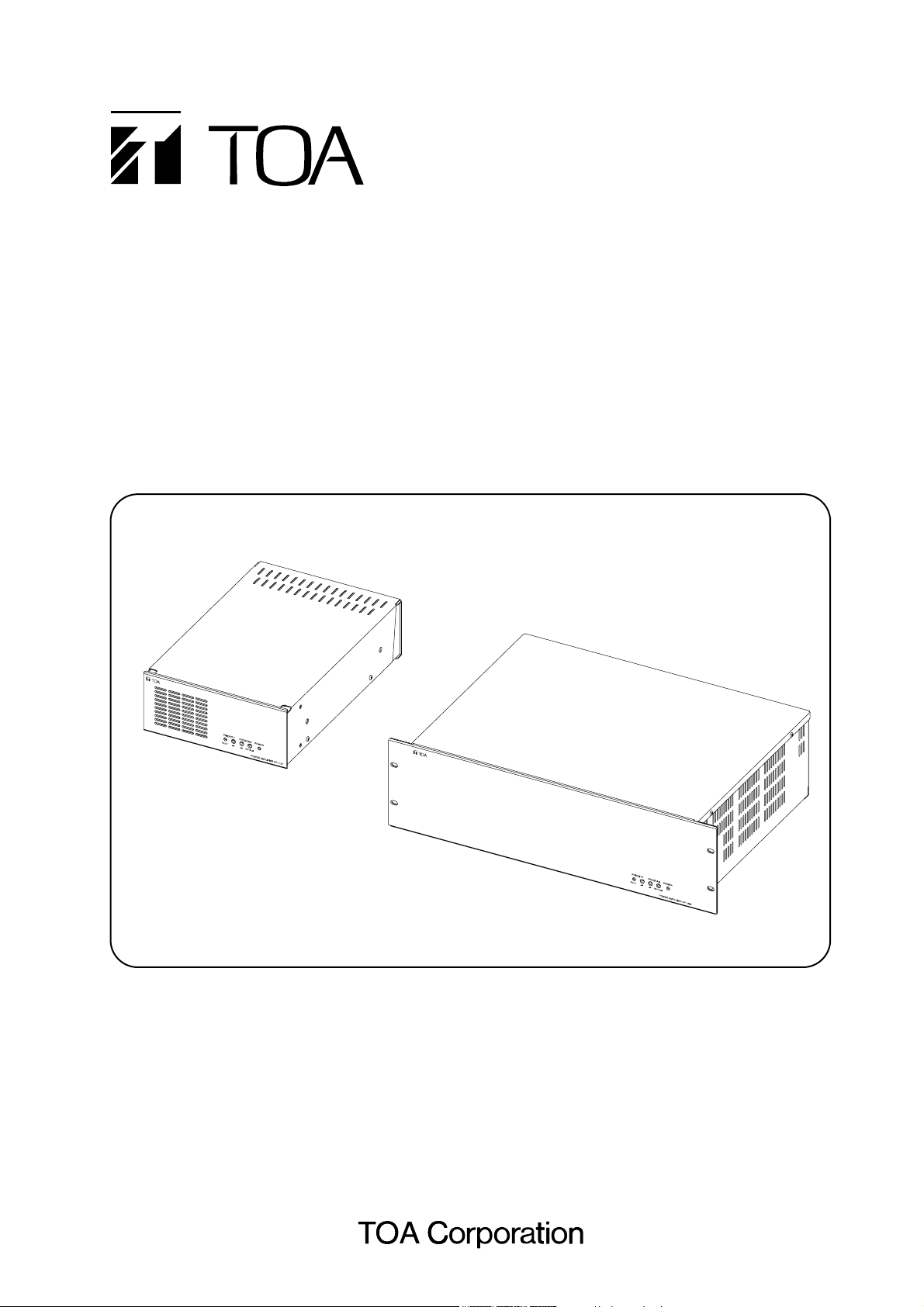
POWER AMPLIFIERS
VP-1061 (60 W)
VP-1121 (120 W)
VP-1241 (240 W)
VP-1361 (360 W)
Thank you for purchasing TOA's Power Amplifier.
Please carefully follow the instructions in this manual to ensure long, trouble-free use of your equipment.
OPERATING INSTRUCTIONS
Page 2

2
TABLE OF CONTENTS
1. SAFETY PRECAUTIONS ............................................................................... 3
2. GENERAL DESCRIPTION ............................................................................. 4
3. FEATURES .......................................................................................................... 4
4. HANDLING PRECAUTIONS .......................................................................... 4
5. INSTALLATION PRECAUTIONS ................................................................. 5
6. NOMENCLATURE AND FUNCTIONS
6.1. Front .................................................................................................................. 5
6.2. Rear.................................................................................................................... 6
7. RACK MOUNTING ............................................................................................ 8
8. REMOVABLE TERMINAL PLUG CONNECTION ................................... 9
9. CONNECTIONS
9.1. Connecting to an AC Power Source ................................................................. 10
9.2. Connecting to a DC Power Supply ................................................................... 10
9.3. Speaker Connection ......................................................................................... 10
9.4. Attenuator Connection ..................................................................................... 10
10. DIMENSIONAL DIAGRAM
10.1. VP-1241, VP-1361 ......................................................................................... 11
10.2. VP-1061, VP-1121 ......................................................................................... 11
11. SPECIFICATIONS ........................................................................................... 12
Accessories ........................................................................................................... 12
Optional Products ................................................................................................... 12
Page 3
3
When Installing the Unit
• Do not expose the unit to rain or an environment
where it may be splashed by water or other liquids,
as doing so may result in fire or electric shock.
• Use the unit only with the voltage specified on the
unit. Using a voltage higher than that which is
specified may result in fire or electric shock.
• Do not cut, kink, otherwise damage nor modify the
power supply cord. In addition, avoid using the
power cord in close proximity to heaters, and never
place heavy objects -- including the unit itself -- on
the power cord, as doing so may result in fire or
electric shock.
• Owing to the unit's size and weight, be sure that at
least two persons are available to install the unit.
Failure to do so could result in personal injury.
• Do not use other methods than specified to mount
the bracket. Extreme force is applied to the unit
and the unit could fall off, possibly resulting in
personal injuries.
• Use a cable of AWG 16 or thicker (VP-1061 and
VP-1121) or AWG 12 or thicker (VP-1241 and VP-
1361) for connecting to the 24 V DC POWER IN
terminal. Also, be sure to firmly screw the cable to
the terminal. Failure to do so may cause the cable
to generate heat, possibly resulting in fire.
• The socket-outlet shall be installed near the
equipment and the plug (disconnecting device)
shall be easily accessible.
• The apparatus shall be connected to a main socket
outlet with a protective earthing connection.
• The terminals marked with the symbol are
hazardous live. The external wiring to these
terminals requires installation by an instructed
person.
When the Unit is in Use
• Should the following irregularity be found during
use, immediately disconnect the power supply plug
from the AC outlet and contact your nearest TOA
dealer. Make no further attempt to operate the unit
in this condition as this may cause fire or electric
shock.
· If you detect smoke or a strange smell coming
from the unit
· If water or any metallic object gets into the unit
· If the unit falls, or the unit case breaks
· If the power supply cord is damaged (exposure of
the core, disconnection, etc.)
· If it is malfunctioning (no tone sounds.)
• To prevent a fire or electric shock, never open nor
remove the unit case as there are high voltage
components inside the unit. Refer all servicing to
qualified service personnel.
• Do not place cups, bowls, or other containers of
liquid or metallic objects on top of the unit. If they
accidentally spill into the unit, this may cause a fire
or electric shock.
• Do not insert nor drop metallic objects or
flammable materials in the ventilation slots of the
unit's cover, as this may result in fire or electric
shock.
• Do not touch a plug during thunder and lightning,
as this may result in electric shock.
• When replacing the fuse, be sure to use the
supplied one or equivalent. Doing otherwise may
cause fire or electric shock.
When Installing the Unit
• Never plug in nor remove the power supply plug
with wet hands, as doing so may cause electric
shock.
• When unplugging the power supply cord, be sure
to grasp the power supply plug; never pull on the
cord itself. Operating the unit with a damaged
power supply cord may cause a fire or electric
shock.
1. SAFETY PRECAUTIONS
• Be sure to read this safety instructions in this section carefully in prior to use.
• Be sure to follow all the precautionary instructions in this section, which contain important warnings and/or
cautions regarding safety.
• After reading, keep this manual handy for future reference.
Safety Symbol and Message Conventions
Safety symbols and messages described below are used in this manual to prevent bodily injury and property
damage which could result from mishandling. Before operating your product, read this manual first and
understand the safety symbols and messages so you are thoroughly aware of the potential safety hazards.
Indicates a potentially hazardous situation which,
if mishandled, could result in death or serious
personal injury.
WARNING
Indicates a potentially hazardous situation which,
if mishandled, could result in moderate or minor
personal injury, and/or property damage.
CAUTION
Page 4

4
2. GENERAL DESCRIPTION
The VP-1061 (60 W), VP-1121 (120 W), VP-1241 (240 W), and VP-1361 (360 W) are 1-channel Power
Amplifiers designed exclusively for rack mount use.
3. FEATURES
• Both the VP-1061 and VP-1121 are 2U* half rack size amplifiers, mountable either alone or side-by-side in a
19" rack.
• Both the VP-1241 and VP-1361 are 3U* full rack size amplifiers.
• Operate on either 230 V AC or 24 V DC.
• An optional YA-1000A Fault Detection Circuit Module can be installed.
• Equipped with Program and Priority inputs, volume level of Program input can be attenuated whenever the
Priority input receives a signal. Attenuation of the volume level is adjustable.
• Input terminals employ removable terminal blocks to provide maximum connection ease.
* 1U size = 44.5 mm (standard size)
4. HANDLING PRECAUTIONS
• It is recommended that the unit be always used in locations where the ambient temperature ranges from 0 to
+40 °C and humidity is less than 90% (no condensation).
• When cleaning the unit, be sure to disconnect the power supply plug from the AC outlet. Wipe with a soft dry
cloth. If it gets very dirty, use the soft cloth slightly moistened in neutral cleanser. Never use thinner,
benzene, chemically processed towels, or alcohol as the unit's plastic or other parts may be deformed or
discolored.
• When moving the unit, be sure to remove its power
supply cord from the AC outlet. Moving the unit
with the power supply cord connected to the outlet
may cause damage to the power supply cord,
resulting in fire or electric shock. When removing
the power cord, be sure to hold its plug to pull.
• Do not block the ventilation slots in the unit's cover.
Doing so may cause heat to build up inside the unit
and result in fire.
• Avoid installing the unit in humid or dusty locations,
in locations exposed to the direct sunlight, near the
heaters, or in locations generating sooty smoke or
steam as doing otherwise may result in fire or
electric shock.
• When unpacking or moving the unit, be sure to
handle it with two or more persons. Falling or
dropping the unit may cause personal injury and/or
property damage.
• To avoid electric shocks, be sure to disconnect the
power supply plug from the AC outlet when
connecting speakers.
• Be sure to follow the instructions below when rackmounting the unit. Failure to do so may cause a fire
or personal injury.
· Install the equipment rack on a stable, hard floor.
Fix it with anchor bolts or take other arrangements
to prevent it from falling down.
· When connecting the unit's power cord to an AC
outlet, use the AC outlet with current capacity
allowable to the unit.
When the Unit is in Use
• Make sure that the volume control is set to
minimum position before power is switched on.
Loud noise produced at high volume when power is
switched on can impair hearing.
• Do not operate the unit for an extended period of
time with the sound distorting. Doing so may cause
the connected speakers to heat, resulting in a fire.
• Contact your TOA dealer as to the cleaning. If dust
is allowed to accumulate in the unit over a long
period of time, a fire or damage to the unit may
result.
• If dust accumulates on the power supply plug or in
the wall AC outlet, a fire may result. Clean it
periodically. In addition, insert the plug in the wall
outlet securely.
• Unplug the power supply plug from the AC outlet
for safety purposes when cleaning or leaving the
unit unused for 10 days or more. Doing otherwise
may cause a fire or electric shock.
Page 5

5
6. NOMENCLATURE AND FUNCTIONS
6.1. Front
VP-1241, VP-1361
1. Power indicator
Lights blue when the power is applied to the unit.
2. Program input mute level control
Program input volume can be muted (attenuated)
by shorting the Priority control input terminals (17).
This control adjusts the attenuation. Turn the
control clockwise to increase attenuation and
counterclockwise to decrease it.
3. Program input volume control
Adjusts the Program input (15) volume.
Turn the control clockwise to increase the volume
and counterclockwise to decrease it.
4. Priority input volume control
Adjusts the Priority input (18) volume.
Turn the control clockwise to increase the volume
and counterclockwise to decrease it.
5. Priority input/Fault indicator
Lights green while the Priority control input
terminals (17) are shorted.
Lights red when the fault detection circuit is
activated. (Operates when the YA-1000A is
mounted.)
VP-1061, VP-1121
5. INSTALLATION PRECAUTIONS
• Avoid using the power supply cord other than the supplied one.
• Keep the input cable away from the output cable. If installed close to each other, oscillation could occur.
• To avoid amplifier failures, never connect outputs of two or more amplifiers in parallel.
• Only connect speakers with an impedance equal to or greater than those specified. Connecting speakers
with a smaller than specified impedance could cause damage to the amplifier.
Page 6

6
6.2. Rear
VP-1241, VP-1361
6. AC inlet
Connect this inlet to the AC power source using
the supplied power cord.
7. AC fuse holder
When replacing the fuse, be sure to use the
supplied one or equivalent shown below.
For fuse replacement, refer to the next page.
8.
Fault detection module slot
Accepts the YA-1000A Fault Detection Circuit
Module.
Note
Leave this work to service personnel. Contact
your TOA dealer.
9. Functional ground terminals
Hum noise may be generated when external
equipment is connected to the unit. Connecting
the case terminal to the functional ground
terminal of the external equipment may reduce
the hum noise.
A ground lift jumper is factory-set between the
Case and Circuit terminals. When this jumper is
removed, the circuit ground can be electrically
disconnected .
Note
This ground is not for protective ground.
10. 24 V DC Power input terminals
Connect to 24 V DC power supply.
11. Emergency relay terminals
Provide relay output.
Switch from "NC" to "NO" in synchronization with
the Priority control input (17).
12. Speaker output terminals
Connect to speakers.
Model Specification of AC fuse
VP-1061 250V T1.25A L
VP-1121 250V T2.5A L
VP-1241 250V T4.0A L
VP-1361 250V T6.3A L
VP-1061, VP-1121
Page 7

7
13. DC Power output terminals
Supply DC power of 24 V, 500 mA to connected
external equipment.
14. Fault output terminals
Not used.
15. Program input terminals
0 dB*, 20 kΩ, balanced
These terminals are internally connected in
parallel to the Program output terminals (16).
The Program input is muted while the Priority
control input terminals (17) are shorted.
16. Program output terminals
These terminals are internally connected in
parallel to the Program input terminals (15).
Connecting these terminals to the other
amplifier's input permits the Program input
signals to be sent to such a connected amplifier.
17. Priority control input terminals
When these terminals are shorted, broadcast
through the Priority input (18) takes precedence
over the one through the Program input (15),
switching the Emergency relay terminals (11)
simultaneously.
18. Priority input terminals
0 dB*, 20 kW, balanced
These terminals are internally connected in
parallel to the Priority output terminals (20).
Broadcast through the Priority input takes
precedence over the one through the Program
input (15) while the Priority control input (17)
terminals are shorted.
19. Priority control output terminals
These terminals are internally connected in
parallel to the Priority control input terminals (17).
20. Priority output terminals
These terminals are internally connected in
parallel to the Priority input terminals (18).
Connecting these terminals to the other
amplifier's input permits the Priority input signals
to be sent to such a connected amplifier.
* 0 dB = 1V
Fuse Replacement
[To remove the fuse]
Step 1. Place the standard screwdriver blade
into the slot in the fuse carrier. Rotate
the fuse carrier counterclockwise while
pressing it firmly.
Step 2. Release pressure and extract the fuse
carrier and the fuse.
[To install the fuse]
Step 1. Insert the fuse carrier with a new fuse
into the holder body slightly by hand.
First, rotate it counterclockwise with a
standard screwdriver.
Note
When installing the fuse carrier, do not insert its
tab into the holder body's groove.
Step 2. Then, rotate the fuse carrier clockwise
to lock while pressing it firmly.
1
First, rotate
counterclockwise.
2
Rotate clockwise
while pressing firmly.
Groove
1
Rotate counterclockwise
while pressing firmly.
2
Fuse carrier comes out.
Page 8

8
7. RACK MOUNTING
[When mounting a single VP-1061 or VP-1121]
Prepare the optional MB-25B-BK Rack Mounting Bracket.
Step 1. Attach the Mount Bracket to the unit's
side using 2 machine screws M4 x 16
and 2 washers supplied with the MB25B-BK.
Step 2. Attach the mount Bracket to the Blank
Panel using 2 tapping screws 4 x 10
supplied with the MB-25B-BK.
Step 3. Attach the Blank Panel to the other side
of the unit using 2 machine screws M4 x
16 and 2 washers supplied with the MB25B-BK.
Tapping screws 4 x 10 *1
Rack Mount Bracket *1
Blank Panel *1
Washers
Machine screws
M4 x 16*1
1
2
3
*1 : components of the MB-25B-BK
List of components of the MB-25B-BK
Mount Bracket 2
Blank Panel 1
Mounting screws 1 set
Step 1. Secure the Joint Bracket supplied with
the MB-25B-J to the bottom sides of the
units using 2 supplied tapping screws 3
x 8.
Step 2. Secure the supplied joint bracket to the
units' rear panels using 2 supplied
tapping screws 3 x 8.
Step 3. Secure the supplied joint bracket to the
units' top panels using 2 supplied
tapping screws 3 x 8.
Step 4. Attach one Mount Bracket to the side of
each unit as shown at right below using
2 sets of 2 machine screws M4 x 16 and
2 washers supplied with the MB-25B-J.
[When linking 2 VP-1061s or VP-1121s]
Prepare the optional MB-25B-J Rack Mounting
Bracket.
Tapping screw 3 x 8 (accessory)
Tapping screw 3 x 8 (accessory)
Joint Bracket (accessory)
Joint Bracket *2
2
1
Tapping screw 3 x 8
(accessory)
Joint Bracket *2
Mount Bracket *2
Washer *2
Machine screw M4 x 16 *2
3
4
List of components of the MB-25B-J
Mount Bracket 2
Joint Bracket 1
Mounting screws 1 set
*2 : components of the MB-25B-J
Page 9

9
Connector Connections
Step 1. Loosen the terminal screw, then insert the cable.
Step 2. Retighten the terminal screw.
Note
Pull on the cable lead to ensure it is securely connected.
8. REMOVABLE TERMINAL PLUG CONNECTION
Note
• Avoid soldering cable conductor, as contact resistance may increase when the cable is tightened and the
solder is crushed, possibly resulting in an excessive rise in joint temperatures.
• Usable cables of AWG 16 - 28.
Cable end treatment
• When mounting 2 or more units in an equipment rack, be sure to mount a perforated panel larger than 1U
size above every 2 stacks of amplifiers as shown in the figure.
*1U size = 44.5 mm (standard size)
• It is recommended that a supporting runner be installed to the rack so that the unit can be easily drawn from
the front of the rack for maintenance purpose.
For the installation procedures of the supporting runner, please contact manufacturer for the rack to be used.
Tip
Recommended slotted screwdriver: Screwdriver with blade that is 3 mm in width.
Perforated panel
VP-1241 or
VP-1361
VP-1061 or
VP-1121
Shielded cable
7 mm
20 mm
Tightens Loosens
2
1
Hot
Earth
Cold
Shielded cable
Slotted screwdriver
1
Terminal screw
Removable terminal
plug
Bit shape 3 mm
Page 10

10
9. CONNECTIONS
9.1. Connecting to an AC power source
Designed for continuous operations, the unit has no power on/off switch on itself.
The unit's power cord should be connected to the Switched AC power outlet of the junction panel so that
power can be turned on and off for the entire amplifier rack.
9.3. Speaker Connection
Only connect speakers with an impedance equal to or greater than those specified.
Note
Connecting speakers with a smaller than specified impedance could cause damage to the amplifier.
9.4. Attenuator Connection
The unit has a built-in relay interlocked with the Priority control input.
The relay provides NC and NO terminals on the unit's rear panel.
For emergency broadcast, attenuators can be connected using either of the following two methods.
[3-wire system] [4-wire system]
Use the DC power cable of AWG 16 or thicker (VP-1061 and
VP-1121) or AWG 12 or thicker (VP-1241 and VP-1361).
Also, be sure to firmly screw the cable to the terminal.
Failure to do so may cause the cable to generate heat,
possibly resulting in fire.
9.2. Connecting to a DC Power Source
When using a 24 V DC external power source, connect it to the DC
input terminals on the unit's rear panel. When the AC power fails, the
power is automatically switched to the DC power.
WARNING
VP-1061 (60 W) 167 Ω
VP-1121 (120 W) 83 Ω
VP-1241 (240 W) 42 Ω
VP-1361 (360 W) 28 Ω
Note
Use the attenuator with relay control terminals that
permit emergency broadcasts to bypass this
attenuator by 24 V DC power.
24 V DC power supply unit
Speaker
RNSP
Attenuator
(+)
(–)
DC Power supply
(–)
(+) N SP
Relay
control
Speaker
Attenuator
Page 11

11
10. DIMENSIONAL DIAGRAMS
10.1. VP-1241, VP-1361
Unit: mm
10.2. VP-1061, VP-1121
337.8
320.5
483.6
465
57.2
37.7
132.6
210
88.4
338.7
321.5
Page 12

* 0 dB = 1V
Power cable (2 m)...................................1
Removable terminal plug (2 pins) ...........2
Removable terminal plug (3 pins) ...........2
Removable terminal plug (5 pins) ...........2
Joint plate ...............................................1 (VP-1061, VP-1121 only)
Joint plate mounting screw .....................3 (VP-1061, VP-1121 only)
Fuse........................................................1 (1.25 A: VP-1061, 2.5 A: VP-1121, 4.0 A: VP-1241, 6.3 A: VP-1361)
11. SPECIFICATIONS
•
Optional Products
133-22-170-5D
URL: http://www.toa.jp/
Fault detector: YA-1000A
Rack mounting bracket: MB-25B-BK (for rack mounting one VP-1061 or VP-1121 unit)
Rack mounting bracket: MB-25B-J (for rack mounting two VP-1061 or VP-1121 unit)
VP-1061 VP-1121 VP-1241 VP-1361
Power Source
230 V AC, 50/60Hz
24 V DC
Power Consumption
AC: (at rated output) 170 W 320 W 537 W 768 W
AC: (EN60065) 100 W 160 W 240 W 330 W
AC: (no-signal) 14 W 19 W 21 W 37 W
DC: (at rated output) 4.5 A 8.2 A 14.6 A 20.9 A
DC: (no-signal) 0.1 A 0.1 A 0.4 A 0.5 A
Rated Output 60 W 120 W 240 W 360 W
Input
2 Program inputs (parallel), 0 dB*, 20 kΩ, balanced
2 Priority inputs (parallel), 0 dB*, 20 kΩ, balanced
Impedance 167 Ω 83 Ω 42 Ω 28 Ω
S/N Ratio 80 dB or more
Total Harmonic Distortion 1% or less (at rated output f = 1 kHz)
Frequency Response 80 Hz – 16 kHz ±3 dB (at 1/3 rated output)
Ventilation Fan cooling
Operating Temperature 0°C to +40°C
Operating Humidity 90% RH or less (no condensation)
Finish Panel: Aluminum, black, alumite
Dimensions 210 (w) x 88.4 (h) x 338.7 (d) mm 483.6 (w) x 132.6 (h) x 337.8 (d) mm
Weight 6.9 kg 9.3 kg 13.4 kg 16.6 kg
•
Accessories
Traceability Information for Europe (EMC directive 2004/108/EC)
Manufacturer:
TOA Corporation
7-2-1, Minatojima Nakamachi, Chuo-ku, Kobe, Hyogo,
Japan
Authorized representative:
TOA Electronics Europe GmbH
Suederstrasse 282, 20537 Hamburg,
Germany
 Loading...