

Page 1
INSTALLATION GUIDE FOR
VM-3000 SERIES
INTEGRATED VOICE EVACUATION SYSTEM
For Service Technicians only
This manual describes works to be performed with the unit's case open.
Leave all these works to a qualified electrician.
Do not pass this manual to users.
Be sure to switch off the system power before starting any work described herein.
Doing otherwise may cause electric shocks.
For switching off the system power, refer to p. 2 in this manual.
WARNING
TABLE OF CONTENTS
1. SWITCHING OFF THE SYSTEM POWER ................................................. 2
2. INPUT TRANSFORMER INSTALLATION AND
MIC INPUT SENSITIVITY CHANGE
............................................................. 3
3. VP-200VX INSTALLATION IN THE VP-2241/2421AND
GROUND LIFT SETTING
3.1. Installing the VP-200VX in the VP-2241/2421 ................................................... 5
3.2. Ground Lifting Using the VP-200VX ................................................................... 6
4. SPEAKER LINE VOLTAGE CHANGE
4.1. VM-3240VA/3360VA and VM-3240E/3360E ...................................................... 7
4.2. VP-2241 and VP-2421 ....................................................................................... 8
5. DC FUSE REPLACEMENT
5.1. VM-3240VA/3360VA and VM-3240E/3360E ...................................................... 9
5.2. VX-2000DS ........................................................................................................ 9
5.3. VP-2241 and VP-2421 ..................................................................................... 10
6. CONNECTING TO THE SX-2000 SYSTEM
6.1. General Description ......................................................................................... 11
6.2. VP-200VX Installation in the VM-3240VA/3360VA .......................................... 12
6.3. Example of Connections between the SX-2100AO, VM-3240VA/3360VA,
and VP-2241/2421 ........................................................................................... 13
6.4. Operating the Combined System of the VM-3240VA/3360VA and
the SX-2000 System ........................................................................................ 14
6.5. Example When the VM-3240VA/3360VA Connected to
the SX-2000 System Fails ................................................................................ 15
Page 2
2
1. SWITCHING OFF THE SYSTEM POWER
When it is necessary to open the equipment's case for modification or change of setting, the system's power
needs to be switched off.
If the DC power supply from the VM-3240VA/3360VA, VM-3240E/3360E, and VX-200PS to the VX-2000DS
stops, the VX-2000DS automatically switches the system's power supply over to the battery. The system
power can be switched off without switching over to the battery by using the VX-2000DS' Setting switch.
Note
Stopping the AC power supply to the VX-2000DS automatically switches the power supply over to the battery.
Take care not to stop the AC power supply to the VX-2000DS.
[To switch off the system power]
Step 1. Terminate all current broadcasts to stop system operation.
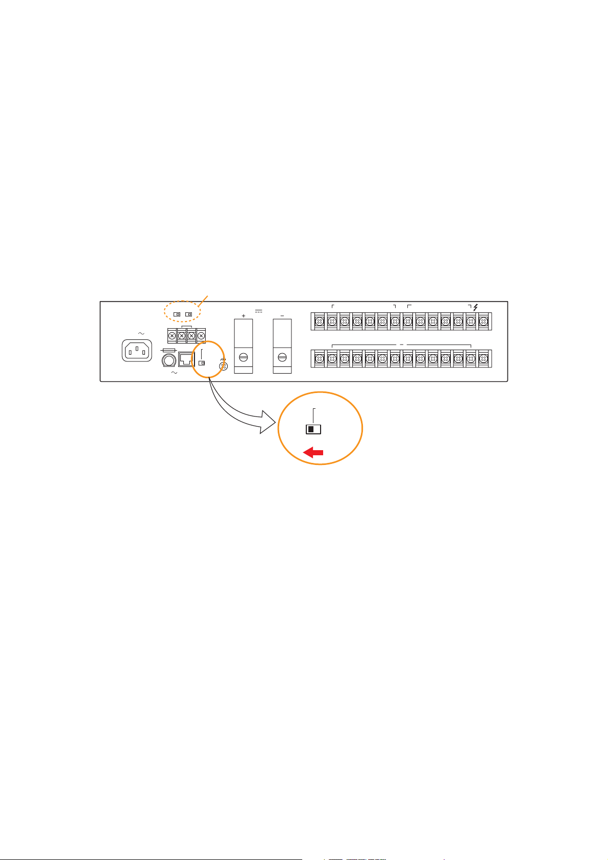
Step 2. Shift the Setting switch on the VX-2000DS's rear panel to the "AC" position.
Step 3. Stop the AC power supply to the VM-3240VA/3360VA, VM-3240E/3360E, and VX-200PS by
disconnecting each unit's AC power cord.
This permits the system power to be switched off without switching over to battery operation if AC
power is supplied to the VX-2000DS.
[To restore the power supply to the system]
Step 1. Restore the AC power supply to the VM-3240VA/3360VA, VM-3240E/3360E, and VX-200PS.
The DC power is supplied from these units to the VX-2000DS.
Step 2. Shift the Setting switch on the VX-2000DS rear panel back to the "DC" position.
Step 3. Operate the system normally.
VX-2000DS Rear
230V
50/60Hz 240W
T3.15A L
DETECT(VX-200PS)
PS3 PS2
THERMISTOR
ER/UK version only
OFFONON OFF
DS – SFFUSE
DS – SF
LINK SETTING
DCAC
BATTERY POWER IN
24V MAX150A
( ) ( )
DC POWER OUT (+) MAX 25A (DC 20V-40V)
SETTING
PS IN (+) MAX 25A (DC20V-40V)
615432615432
( )
PS IN
1,2:PS1
3,4:PS2
5,6:PS3
DCAC
Setting switch
Page 3
3
2. INPUT TRANSFORMER INSTALLATION AND MIC INPUT SENSITIVITY
CHANGE
• Each of the MIC inputs 1 to 3 (electronically balanced) can be converted to a transformer-balanced input by
installing an optional input transformer IT-450 on the PC board.
• Each sensitivity of the MIC inputs 1 to 3 can be changed from –50 dB (factory-preset) to –30 dB by cutting
the corresponding jumper wire on the input PC board.
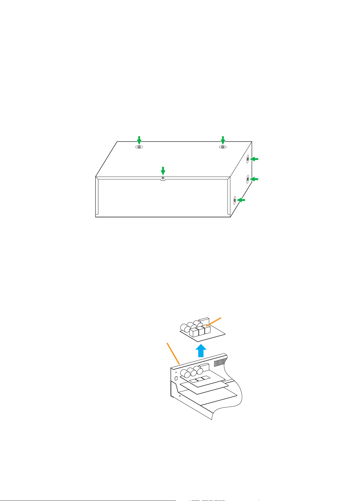
Step 1. Remove the screws securing the VM-3240VA/3360VA's cover (3 pieces on each side, 2 on the top,
and 1 on the rear) to detach the cover.
Step 2. Remove the input PC board.
The input PC board is fixed to the unit's rear panel with 8 screws.
Unscrew the PC board to detach it.
Step 3. To convert the electronically balanced input to a transformer-balanced one, install and solder the IT-
450 transformer at the corresponding location on the PC board.
Binding screw M4 x 8
VM-3240VA/3360VA
Input transformer
VM-3240VA/3360VA's rear panel
Page 4
4
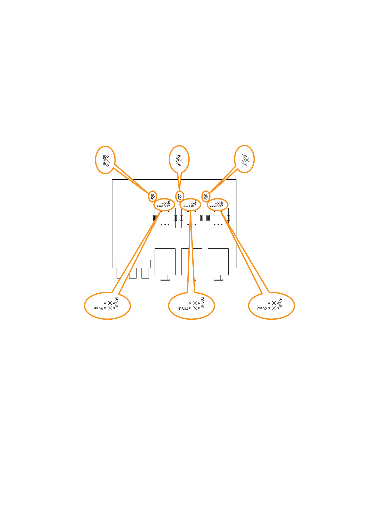
Step 4. Cut the jumper wires designated according to purposes referring to the PC board diagram showing
the jumper wire locations below.
4-1. To convert the electronically balanced input to a transformer-balanced one
Cut the jumpers (a), (b), or (c) corresponding to the transformer-installed input on the pc board.
4.2. To change the microphone input sensitivity
Cut the jumper (d), (e), or (f) corresponding to the desired MIC input on the pc board.
Step 5. Replace the input PC board.
Step 6. Replace the cover.
4
-2
(f) JP509:
Jumper for MIC input 3
sensitivity change
VM-3240VA/3360VA
(e) JP508:
Jumper for MIC input 2
sensitivity change
(Front side)
(d) JP507:
Jumper for MIC input 1
sensitivity change
4
-1
(c) JP505 and JP506:
Jumpers for input 3
balanced type conversion
(b) JP503 and JP504:
Jumpers for input 2
balanced type conversion
(a) JP501 and JP502:
Jumpers for input 1
balanced type conversion
Page 5
5
3. VP-200VX INSTALLATION IN THE VP-2241/2421 AND
GROUND LIFT SETTING
3.1. Installing the VP-200VX in the VP-2241/2421
Step 1. Remove the VP-2241/2421 power amplifier's top panel.
Step 2. Unscrew the VP-200VX's panel to detach it.
Step 3. Mount the VP-200VX module.
Attach the VP-200VX's panel to the mounting location and the VP-200VX unit to the back of the
mounting location, then secure them to the amplifier using the screws removed in step 2.
Note: Mount the VP-200VX with its circuit board components faced down.
VP-2241/2421
VP-200VX
VP-200VX 's panel
Mounting screw
(Use the screw removed
from the VP-200VX)
Page 6

6
Step 4. Plug the VP-200VX's connector into the CN106 connector on the circuit board inside the amplifier.
[VP-2241/2421 Connector position]
Step 5. After mounting is completed for all required channels, replace the top panel.
3.2. Ground Lifting Using the VP-200VX
When operating the system, hum noise may be generated by a ground loop accidentally created in the
system. The ground loop can be cut off with the Ground Lift jumper connector setting on the VP-200VX board.
Step 1. Remove the VP-2241/2421 unit's top panel referring to p. 5, step 1.
Step 2. Take out the VP-200VX.
Step 3. Unplug the jumper socket and plug it to the LIFT position on the VP-200VX board as shown below.
Step 4. Fit the VP-200VX back into place.
Step 5. Replace the top panel.
DRIVE PCB
CN106
Rear panel
VP-200VX
Factory-preset position
LIFT
Ground Lift position
LIFT
LIFT
Page 7

7
4. SPEAKER LINE VOLTAGE CHANGE
4.1. VM-3240VA/3360VA and VM-3240E/3360E
The VM amplifier's speaker line voltage is set for 100 V line output. For 50 V or 70 V line applications, change
internal connector wiring as shown below.
Note
The speaker line failure detection functions are designed to perform on a 100-volt line of speaker. Set these
functions to OFF if the amplifier’s speaker line voltage is set to 50 V or 70 V. For the methods using a 70- or
50-volt line, please consult your TOA dealer.
Step 1. Remove the top cover referring to p. 3, step 1.
Step 2. Pull the cable connector (9-pin) connected to CN182
connector on the circuit board with the output attenuators.
Step 3. Change wires inserted into the cable connector for different
wires according to color-coding shown in the table below to
switch to the desired line voltage.
Step 4. Connect the cable connector to the circuit board.
Step 5. Replace the top cover.
[Connector pin assignment]
Speaker line voltage CN182 Connector Pin Number
123456789
100 V White Violet Blue Green Yellow Orange Red Brown Black
70 V Violet Blue Green Yellow Orange Red Brown White Black
50 V Blue Green Yellow Orange Red Brown White Violet Black
[Speaker line voltage/impedance]
Speaker line voltage VM-3240 VM-3360
100 V 42 Ω 28 Ω
70 V 21 Ω 14 Ω
50 V 10 Ω 7 Ω
[How to remove cables from connector]
Pull out the cable pressing the lock spring with a pointed object like tweezers as shown below.
VM amplifier
CN182 connector
(Front side)
Pull out the cable.
Press the lock spring.
1
9
Page 8

8
4.2. VP-2241 and VP-2421
The speaker line voltage of the VP-2241 and VP-2421 is factory-preset to 100 V, however this can be
changed to 50 V or 70 V by following the procedures below.
Note
The speaker line failure detection functions are designed to perform on a 100-volt line of speaker. Set these
functions to OFF if the amplifier’s speaker line voltage is set to 50 V or 70 V. For the methods using a 70- or
50-volt line, please consult your TOA dealer.
Step 1. Remove the top panel referring to p. 5, step 1.
Step 2. Remove the CN-102 connector.
Step 3. Change the wiring in the CN102.
To change to 50 V line: Exchange Pin 1's cable (white) with Pin 3's cable (blue).
To change to 70 V line: Exchange Pin 1's cable (white) with Pin 2's cable (purple).
Step 4. Reconnect the CN102 to the original position on the circuit board.
Step 5. Replace the top panel.
[Speaker line voltage/impedance]
Speaker line voltage VP-2241 VP-2421
100 V 41 Ω 24 Ω
70 V 21 Ω 12 Ω
50 V 10 Ω 6 Ω
[How to remove cables from connector]
Pull out the cable pressing the lock spring with a pointed object like tweezers as shown below.
[VP-2241 Connector position] [VP-2421 Connector position]
CN102
CN102
Rear panel Rear panel
Pull out the cable.
Press the lock spring.
1
9
Page 9

9
5. DC FUSE REPLACEMENT
When the DC fuse inside the unit has blown, replace it with a new one following the procedure below.
5.1. VM-3240VA/3360VA and VM-3240E/3360E
Step 1. Remove the top cover referring to p. 3, step 1.
Step 2. Confirm the rating of the blown fuse, then replace the fuse with the supplied one.
Step 3. Replace the top cover.
5.2. VX-2000DS
Fuses can be accessed from the top of the VX-2000DS.
Confirm the blown fuse, then replace it with the supplied one.
Blade fuses:
25 A (Common to the
VM-3240VA/3360VA)
Rear panel
VX-2000DS
(Front side)
Blade fuses:
15 A (VM-3240VA/3240E),
25 A (VM-3360VA/3360E)
Tube fuse:
250 V T2AL (Common to all models)
654321
FUSE 40A (DC POWER OUT)
Blade fuses: 40 A each (6 pieces)
Page 10

5.3. VP-2241 and VP-2421
Step 1. Remove the top cover referring to p. 5, step 1.
Step 2. Replace the blown fuse with the supplied one.
VP-2241: Blade fuse 25 A
VP-2421: Blade fuse 35 A
Step 3. Replace the top panel.
10
[VP-2241/2421 Blade fuse position]
Blade fuse
DRIVE PCB
Rear panel
Page 11

11
6. CONNECTING TO THE SX-2000 SYSTEM
Note
This function can be used only when all the versions of VM-3240VA/3360VA firmware, VM-3240E
/3360E firmware, and VM-3000 Setting Software are 2.00 or later and SX-2000 system ver. 3.00 or later.
6.1. General Description
Additionally connecting the VM-3240VAs/3360VAs to the SX-2000 system allows the SX-2000 system's
speaker line capacity to increase by 6 speaker lines per a single VM-3240VA/3360VA. In this case, the entire
system operates as shown below.
• The VM-3240VAs/3360VAs perform only 1-channel broadcasting (no standby amplifier).
• The SX-2000 checks for the VM-3240VA/3360VA amplifier failure, and the line failure between VM-
3240VA/3360VA amplifier and the SX-2000 amplifier.
• The VM-3240VA/3360VA checks for the speaker line failure.
Besides, adding the VP-2241 or VP-2421 amplifier to the SX-2000 system as a standby amplifier maintains
the general-purpose broadcast operation even if the VM-3240VA/3360VA fails.
Notes
• The VM-3240E/3360E cannot be used in this system.
• In the system where the VM-3240VA/3360VA and the SX-2000 system are combined, the VM-
3240VA/3360VA cannot be used as Emergency broadcast equipment.
• Never place the VM-3240VA/3360VA in emergency mode nor operate emergency EV, RM-300MF, and front
emergency microphone to prevent the entire system from malfunction.
• Audio Input 4 is reserved. (See the table of VM-3000 Settings.)
[Settings on the software when using the VM-3000 and SX-2000 in combination]
SX-2000 settings (Refer to the Setting Software manual attached to the SX-2000 unit.)
Important: Set to ON the front-mounted DIP switch No. 2 of SX-2100AO used for combination mode.
VM-3000 settings (Refer to the separate Setting Software manual.)
Important: Set to ON the rear-mounted DIP switch 6 of VM-3240VA/3360VA to disable surveillance of the
front emergency microphone.
Menu Item Item Setting
SX-2100AO Surveillance
Pattern Setting
Event Interlocked control output must be set together with zone selection.
Amplifier
Loudspeaker Line
Zone Pattern
Control Output Pattern
ON
OFF
Control Output Pattern must be set for each zone output to be
connected to VM-3240VA/3360VA.
Menu Item
System
Priority
Zone
System Type
Number of VM-3000Es
Remote Microphone
VM-3000VA
Emergency EV
Speaker (Open/Short)
Speaker (Earth Fault)
Emergency Control Input
Input 4
Any other inputs (including EV and RM)
Zone 90
General Control Input 8
Item Setting
Standby amplifier: Not used
0
RM-300MF should not be configured.
ON
OFF
ON
ON
OFF
Priority 1
Note: Any sound source should not be connected to Input 4.
Priority 2 or lower
All outputs should be selected. (Default)
Function:
Contents 1:
VA-INPUT 4
Zone 90 (All zones selection)
Page 12

12
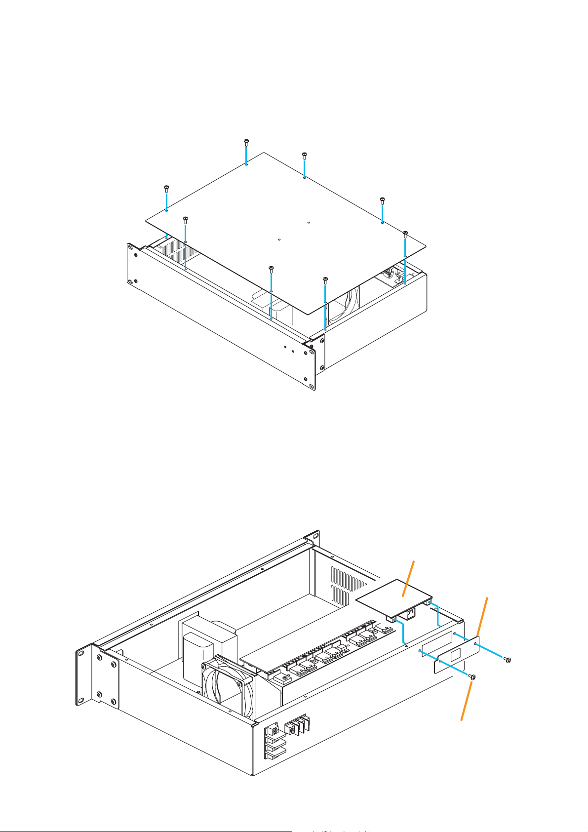
6.2. VP-200VX Installation in the VM-3240VA/3360VA
Step 1. Remove the screws securing the VM-3240VA's/3360VA's cover (3 pieces on each side, 2 on the top,
and 1 on the rear) to detach the cover. (Refer to p. 3.)
Step 2. Make an opening for mounting the PA LINK connector by removing the
knockout plate on the VM-3240VA's/3360VA's rear.
Step 3. Remove 2 screws on the VP-200VX's front panel to detach it. (This removed panel is not used.)
Install the VP-200VX (without the front panel) inside the VM-3240VA/3360VA, then secure it with the
removed screws.
Step 4. Connect the VP-200VX's harness to the connector (CN1101) on the VM-3240VA's/3360VA's CPU
circuit board.
Step 5. Replace the VM-3240VA's/3360VA's cover by securing with the screws removed in step 1.
VP-200VX's panel
Detach the front panel.
CN1101
VP-200VX
CPU circuit board
VM-3240VA/3360VA
Page 13

13
6.3. Example of Connections between the SX-2100AO, VM-3240VA/3360VA,
and VP-2241/2421
SX-2100AO
AWG 20 – 16
AWG 20 – 16
VM-3240VA/3360VA
Cat. 5 STP
VP-2241/2421
DC POWER IN
28 V 4.8 A
PA OUT (SP LINE)
PA OUT (SP LINE)
CH
CH
PA LINK VP-200VX
PA LINK
Cat. 5 STP
VP-200VX
Page 14

14
6.4. Operating the Combined System of the VM-3240VA/3360VA and
the SX-2000 System
Note
For installation, check the SX-2000 and VM-3000 settings by referring to the tables on p. 11.
Step 1. Power up or restart the VM-3240VA/3360VA after installing the VP-200VX in it.
Then, the VM-3240VA/3360VA recognizes the VP-200VX, making the VM-3240VA's/3360VA's
general control input terminal No. 8 have a function to shut off all audio signals input to the VM3240VA/3360VA when this terminal receives the control signal.
Step 2. Perform the general control input No. 8 setting on the VM-3000 Setting Software screen as shown
below. (For details, refer to the separate VM-3000 software instruction manual.)
Step 3. Apply a control signal to the VM-3240VA's/3360VA's general control input terminal No. 8.
Then, audio signals input to the VM-3240VA/3360VA are all shut off.
Page 15

15
Step 4. Perform broadcasts from the SX-2000 system.
Audio signals input to the SX-2000 system enter the VM-3240VA/3360VA, return to the SX-2100AO,
and enter the VM-3240VA/3360VA again, and are finally output from the VM-3240VA's/3360VA's SP
OUT terminal. (Refer to the diagram below.)
[Audio signal flow when the VM-3240VA/3360VA is connected to the SX-2000 system]
Audio sources being previously broadcast are shut off by a control signal from the SX-2100AO. Instead, audio
signals entering the VM-3240VA/3360VA from the SX-2100AO are broadcast.
6.5. Example When the VM-3240VA/3360VA Connected to the SX-2000 System Fails
If the VM-3240VA/3360VA fails, audio signals from the SX-2100AO being previously broadcast are shut off.
Instead, another audio signals from the SX-2100AO are broadcast by the standby amplifier.
SX-2100AO VM-3240VA/3360VA
CONTROL OUTPUT (C/NO)
Control signal
CTR 8
2
*
VM-3240VA/3360VA's
1
VP-200VX
DIRECT OUT
EXT. AMP
OUTPUT 1 – 6
Audio signals
PA LINK (ZONE 1)
ZONE 1 (AMP)
ZONE 1 (SP)
STANDBY AMP
Audio Inputs*
VP-2241/2421
Audio signals
1
Not broadcast because these audio signals are shut off when the control signal from the SX-2100AO is fed to the
*
STANDBY
VP-200VX
VM-3240VA's/3360VA's CTR 8.
2
GENERAL CONTROL INPUT 8 of VM-3240VA/3360VA*
SX-2100AO VM-3240VA/3360VA
2
*
CTR 8
VP-200VX
DIRECT OUT
EXT. AMP
VP-200VX
Amplifier
failure
OUTPUT 1 – 6
Audio signals
Audio signals
CONTROL OUTPUT (C/NO)
PA LINK (ZONE 1)
ZONE 1 (AMP)
ZONE 1 (SP)
STANDBY AMP
STANDBY
Control signal
VM-3240VA/3360VA's
Audio Inputs
VP-2241/2421
2
GENERAL CONTROL INPUT 8 of VM-3240VA/3360VA*
Page 16

201010
URL: http://www.toa.jp/
 Loading...