

Page 1

For Qualified Service Technicians only
INSTALLATION INSTRUCTIONS FOR SYSTEM
MANAGEMENT AMPLIFIERS VM-2120 AND VM-2240
This manual gives qualified service technicians the instructions for the work in the TABLE OF
CONTENTS below.
Use this manual referring to the instruction manual supplied with the VM-2120 or VM-2240 System
Management Amplifier.
Note that the section numbers and names in this manual are the same as those in the VM-2120/-2240
instruction manual.
TABLE OF CONTENTS
13. CHOKE COIL INSTALLATION ............................................................................................ 2
14.
INPUT TRANSFORMER INSTALLATION AND ITS BOARD MODIFICATION
14.1. Transformer Installation ......................................................................................................... 3
14.2. Switching Off the Phantom Power Supply ............................................................................. 4
14.3. Instructions When the Sub- and Master VM Amplifiers Are Connected ................................ 4
15. MOUNTING AN OPTIONAL EV-200 VOICE ANNOUNCEMENT BOARD ............ 5
16. MOUNTING AN OPTIONAL SV-200M SURVEILLANCE BOARD ........................... 7
20. CHANGING THE SPEAKER LINE VOLTAGE ................................................................ 9
23. FUNCTION SWITCH OPERATION
23.2. VM Amplifier's Internal Function Switches .......................................................................... 10
USE OF VR COVERS (Described only in this manual) ..................................................... 11
English: page 1
Deutsch: seite 13
Français: page 25
Page 2
2
13. CHOKE COIL INSTALLATION
Caution: Leave the following work to a qualified service technician.
Be sure to unplug the AC power cord before the work.
If a checkbox for the indication of "The choke coil is installed." on the rear panel of the VM amplifier is marked
with "X", this represents that the choke coil has been installed. Therefore, the following tasks are not
necessary. When you installed the choke coil, mark the checkbox with "X".
To suppress harmonic component radiation from the power line of the unit, install the optional Chock Coil CT200M.
Note: In the countries where use of the CE Marking conformity is obligated, the Choke Coil must be installed.
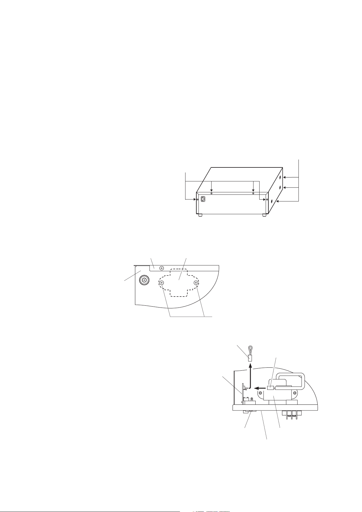
Step 1. Remove 4 screws on the amplifier rear panel and a total of 6 screws on the sides to remove the
cover.
Step 2. Install the Chock Coil near the AC inlet inside the unit.
Fix the Choke Coil with its accessory screws from the unit bottom side.
Step 3. Remove the jumper connector from the
power input board connector (CN1202).
Step 4. Plug the Choke Coil connector into the
power input board connector (CN1202).
Step 5. Using the 4 rear panel screws and 6 side panel screws removed in Step 1, replace the amplifier
cover.
Side: M4 x 8 machine screw ..... 3 pieces each
Rear: M3 x 6 machine screw and M3 plain washer ..... 4 pieces
Rear panel
Bottom side
CT-200M Choke coil
Jumper connector
Power input board
Tapping screw 4 x 10
Choke coil connector
3
4
AC inlet
CT-200M Choke coil
Rear panel
Page 3
3
14. INPUT TRANSFORMER INSTALLATION AND ITS BOARD MODIFICATION
Caution: Leave the following work to a qualified service technician.
Be sure to unplug the AC power cord before the work.
14.1. Transformer Installation
You can convert the audio input section in Input 1 – 3 terminals, Remote Microphone (RM) terminal, and
Telephone Paging (TEL) terminal on the unit from electronically-balanced input to transformer-balanced type.
Solder the optional IT-450 input transformer to the required input section.
Step 1. Remove 4 screws on the amplifier rear panel and a total of 6 screws on the sides to remove the
cover.
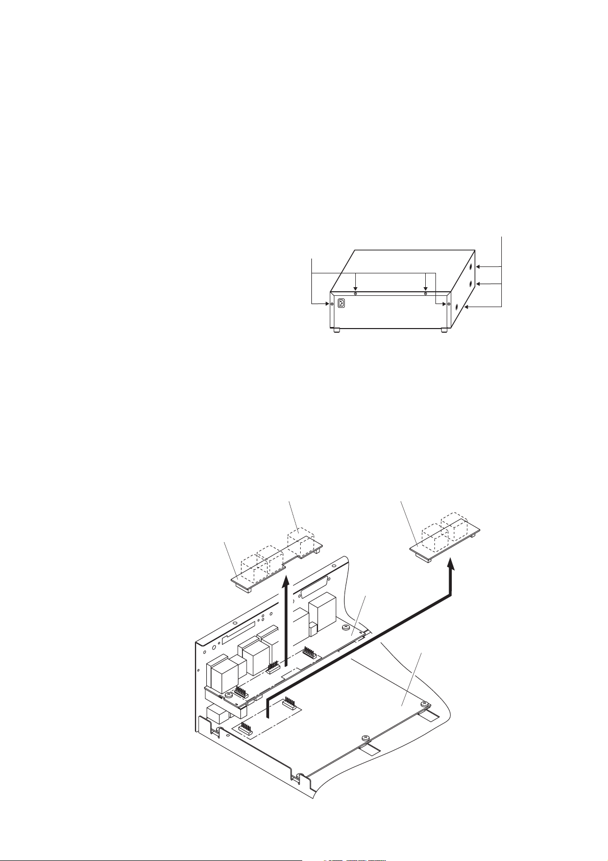
Step 2. Removing the input transformer board
[Inputs 1 – 3]
Remove the Inputs 1 – 3 input transformer board, which is installed on the rear upper circuit board in
the unit.
[Remote Microphone (RM) or Telephone Paging (TEL)]
Remove the RM/TEL input transformer board, which is installed on the rear lower circuit board in the
unit.
Side: M4 x 8 machine screw ..... 3 pieces each
Rear: M3 x 6 machine screw and M3 plain washer ..... 4 pieces
Input transformer
Inputs 1 – 3 input transformer board
RM/TEL input transformer board
Rear upper
circuit board
Rear lower circuit board
Page 4

4
Step 3. Solder the input transformer to the removed input transformer board (5 places).
Note: Be sure not to mistake the solder side for the mounting side.
Step 4. Cut off jumper wires (2 places marked with X for each input).
Note: The jumpers are on the back of the circuit board in the figure below.
[Inputs 1 – 3 input transformer board]
[RM/TEL input transformer board]
Step 5. Replace the input transformer board on the circuit board.
Step 6. Using the 4 rear panel screws and 6 side panel screws removed in Step 1, replace the amplifier
cover.
14.2. Switching Off the Phantom Power Supply
By cutting the following jumper wires on the Inputs 1 – 3 Input Transformer Board, the corresponding input's
phantom power can be switched off. (See the figure above.)
Input 1: SJP1301
Input 2: SJP1304
Input 3: SJP1307
14.3. Instructions When the Sub- and Master VM Amplifiers Are Connected
• Be sure to cut the jumper wires SJP1401, SJP1402, and SJP1403 on the RM/TEL input transformer board in
the sub-VM amplifier.
• To make the Remote Microphone (RM) input transformer-isolated, be sure to install the input transformer on
the RM/TEL input transformer board in the master VM amplifier. In addition, cut the jumper wires SJP1402
and SJP1403 while remaining SJP1401 intact.
Jumpers for Input 1
(SJP1303)
INPUT 1 INPUT 2 INPUT 3
(SJP1301)
(SJP1302)
Jumper for Input 1
phantom power supply
(SJP1402)
Jumpers for RM
(SJP1403)
Jumpers for Input 2
(SJP1401)
RM TEL
(SJP1305)
(SJP1306)
(SJP1304)
(SJP1307)
Jumper for Input 2
phantom power supply
Jumpers for Input 3
(SJP1308)
(SJP1309)
Jumper for Input 3
phantom power supply
(SJP1404)
Jumpers for TEL
(SJP1405)
Jumper for DC power supply to the RM
Page 5
5
15. MOUNTING AN OPTIONAL EV-200 VOICE ANNOUNCEMENT BOARD
Caution: Leave the following work to a qualified service technician.
Be sure to unplug the AC power cord before the work.
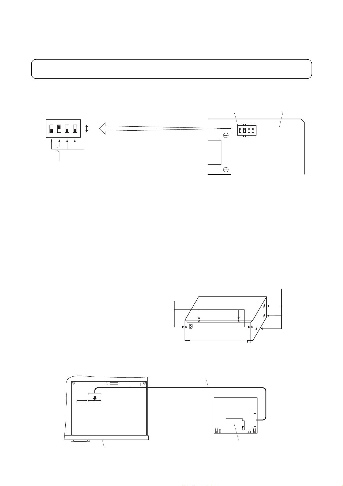
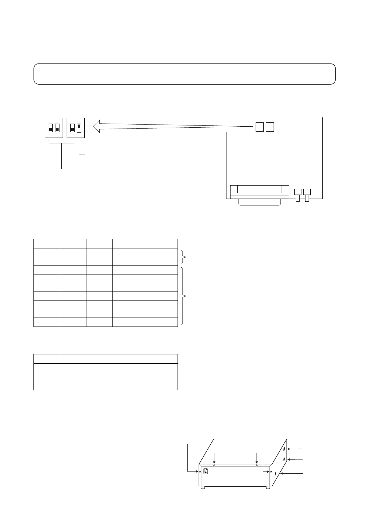
Step 1. Set the DIP switch on the EV-200 Board as shown in the figure.
EV-200 surveillance signal output (Switch No. 2)
The EV-200 board always transmits a 1 kHz sine wave signal to an amplifier when the EV-200 Board is not
reproducing audio signals. The amplifier detects the existence of the 1 kHz signal. When the signal does not
exist, the amplifier judges the board's failure and causes the FAULT indicator to light.* (The signal indicating
the EV-200's failure is transmitted from the CONTROL I/O connector.)
* If Switch No. 2 is set to the OFF position, the FAULT indicator lights even when the board is operating
correctly.
Step 2. Remove 4 screws on the amplifier rear panel and a total of 6 screws on the sides to remove the
cover.
Step 3. Insert the EV-200 connection cable coming from the EV-200 Board into connector CN8 in the
amplifier.
Do not handle unless your body is static-free because some of the assembled components are
sensitive to static electricity.
DIP switch
EV-200 Board
DIP switch
ON
3
4
OFF
SW 1
1
3
4
2
F
F
O
SW 1
1
2
F
F
O
Always set to OFF.
(ON position is for factory test.)
EV-200 surveillance signal output on-off (Switch No. 2)
Be sure to set to ON. (A 1 kHz signal output)
Side: M4 x 8 machine screw ..... 3 pieces each
Rear: M3 x 6 machine screw and M3 plain washer ..... 4 pieces
EV-200 connection cable
CN6
CN8
Rear panel
EV-200 Board
CF card connector
Page 6
6
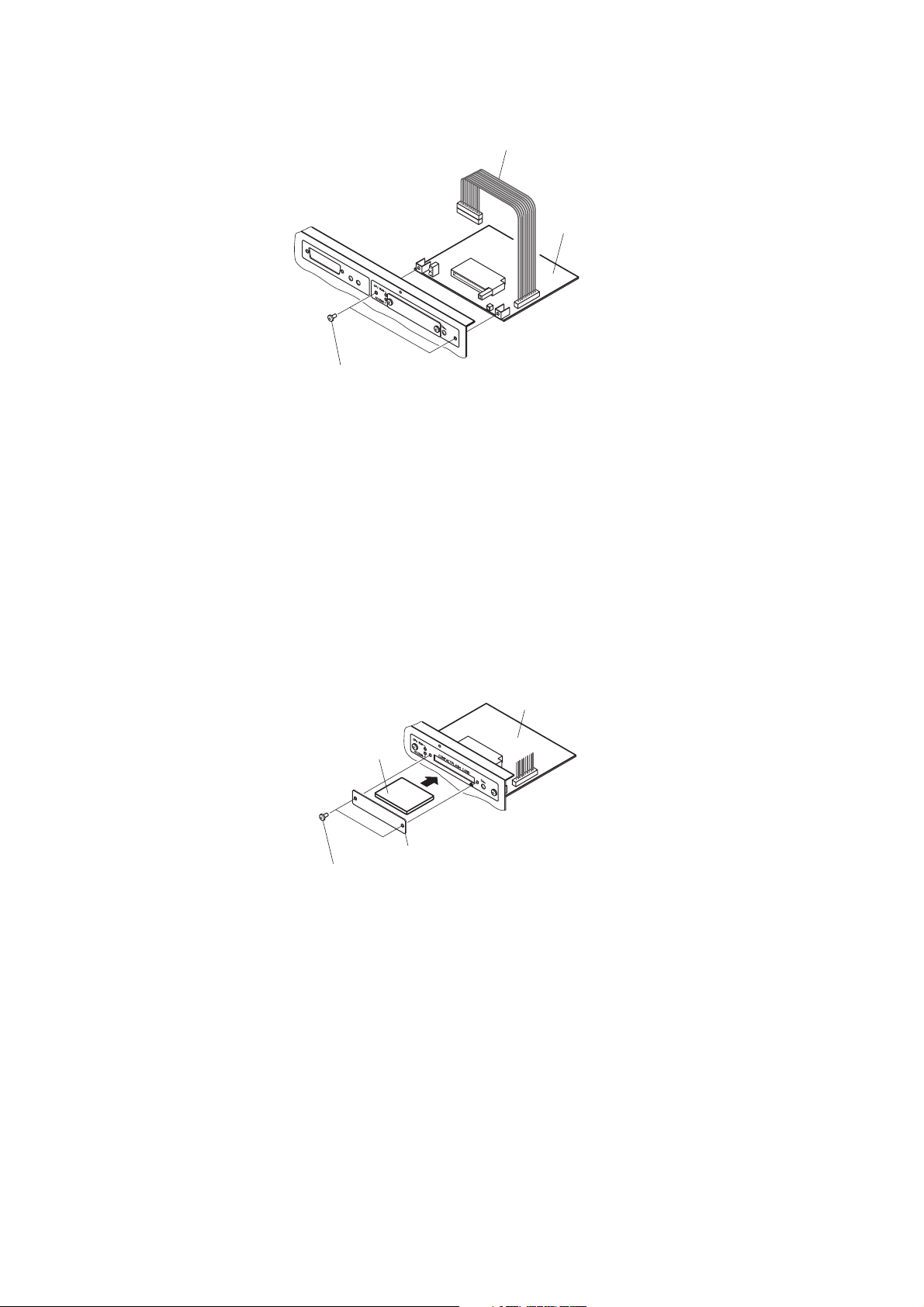
Step 4. Using 2 screws supplied with the EV-200, mount the EV-200 in the amplifier.
Step 5. Check the DIP switch on the EV-200 Board again for correct setting. (See Step 1.)
Step 6. Using the 4 rear panel screws and 6 side panel screws removed in Step 2, replace the amplifier
cover.
CF Card security cover
Remove 2 screws to detach the security cover when inserting the CF Card into the card slot. Be sure to
replace the cover after inserting the card.
EV-200 connection cable
CN8
M3 x 6 machine screw ..... 2 pieces (supplied with the EV-200)
EV-200 Board
EV-200 Board
CF Card
CF Card security cover
M3 x 4 machine screw (2 pieces)
Page 7
7
16. MOUNTING AN OPTIONAL SV-200M SURVEILLANCE BOARD
Caution: Leave the following work to a qualified service technician.
Be sure to unplug the AC power cord before the work.
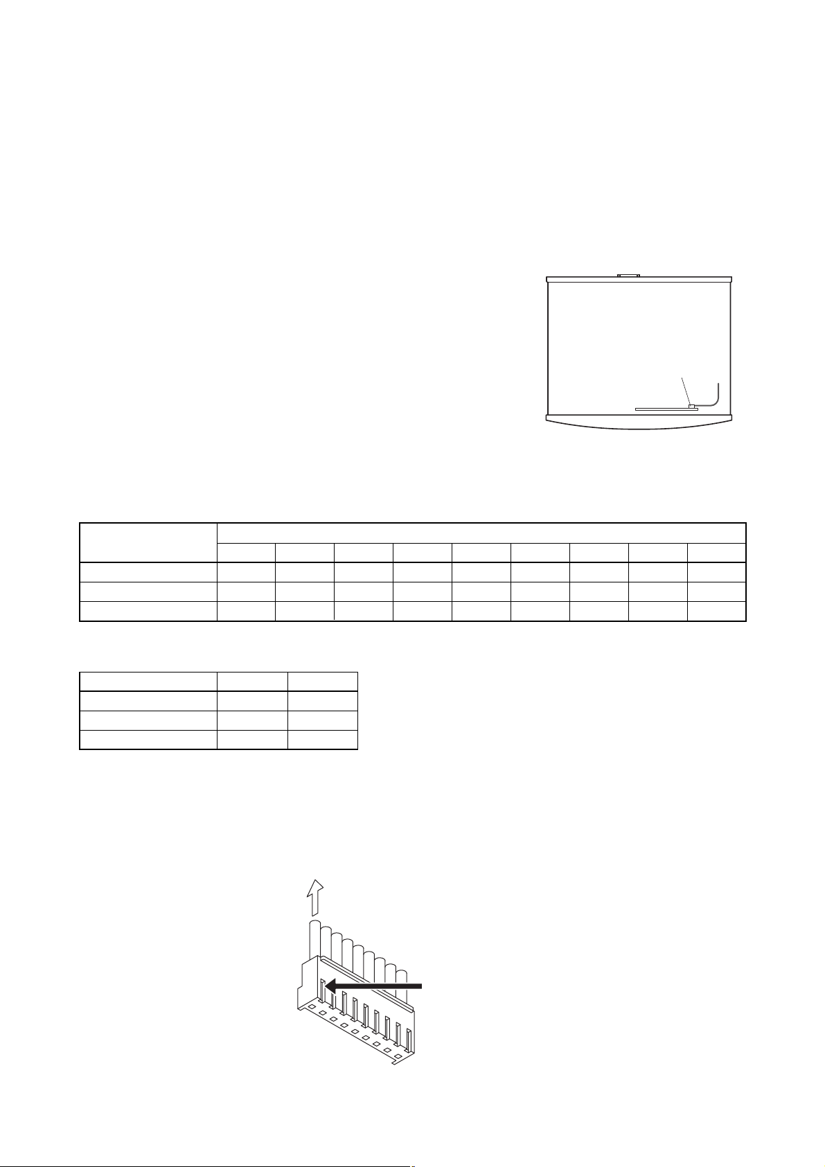
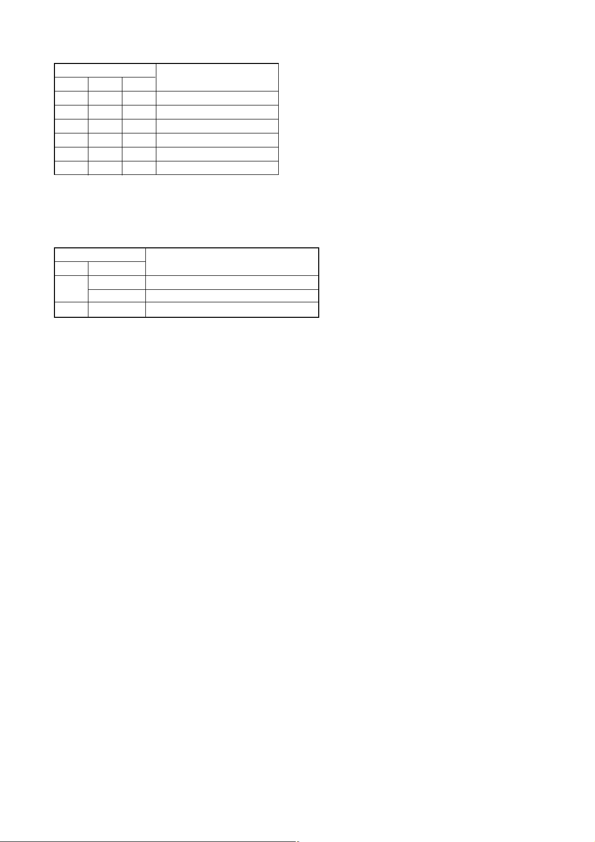
Step 1. Set the DIP switch on the SV-200M Board as shown in the figure.
Speaker line surveillance activation time
SW1-1 SW1-2 SW2-1 Setting contents
OFF OFF OFF
Automatic activation
disabled
ON OFF OFF
10 minutes intervals
OFF ON OFF
20 minutes intervals
ON ON OFF
30 minutes intervals
OFF OFF ON
30 minutes intervals
ON OFF ON
40 minutes intervals
OFF ON ON
50 minutes intervals
ON ON ON
60 minutes intervals
This setting executes failure detection by means of
the "speaker line surveillance activation" signal from
the external control input (SURVEILLANCE I/O 25pin D-sub connector).
Speaker lines are automatically monitored at set
time intervals.
SW2-2 Setting contents
OFF
Disabled (communications impossible)
ON
Enabled (when SV-200M Board is
installed in VM amplifier)
Communications with VM (VM-2120 or VM-2240) amplifier
Step 2. Remove 4 screws on the amplifier rear panel and a total of 6 screws on the sides to remove the
cover.
Do not handle unless your body is static-free because some of the assembled components are
sensitive to static electricity.
SW 1 SW 2
ON
1
Speaker line surveillance activation time
ON
1
2
2
Communication with VM amplifiers
Be sure to set to ON.
SW 1 SW 2
SV-200M Board
Side: M4 x 8 machine screw ..... 3 pieces each
Rear: M3 x 6 machine screw and M3 plain washer ..... 4 pieces
Page 8
8
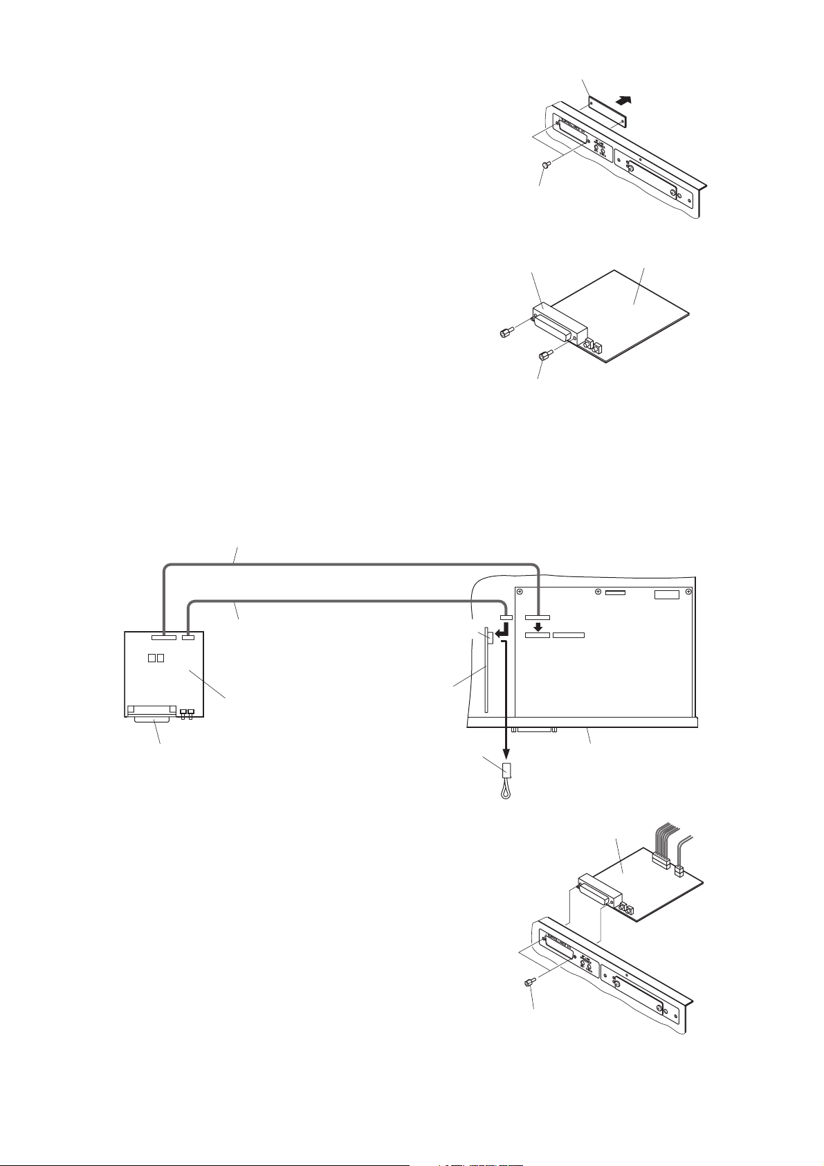
Step 3. Detach the surveillance I/O blank panel on the
amplifier rear panel by removing 2 fixing snap rivets.
Step 4. Unscrew 2 hexagonal sleeves mounted on the 25-pin
D-sub connector on the SV-200M Board.
Step 5. Connect the SV-200M Board to the VM amplifier's boards with the connection cables.
5-1. Plug out the jumper connector from the relay board connector (CN1003) shown below.
5-2. Connect the 2 cables attached to the SV-200M to the connectors in the VM amplifier's boards shown
below.
Step 6. Using the removed 2 hexagonal sleeves,
mount the SV-200M in the amplifier.
Step 7. Check the DIP switch on the SV-200M Board again
for correct setting. (See Step 1.)
Step 8. Using the 4 rear panel screws and 6 side panel screws removed in Step 2, replace the amplifier
cover.
Surveillance I/O blank panel
Snap rivet
D-sub connector
Hexagonal sleeve
CN6 connection cable
5
-2
CN1003 connection cable
CN1003
CN6
CN8
SV-200M Board
SV-200M Board
D-sub connector
Relay board
Jumper connector
5
-1
Rear panel
SV-200M Board
Hexagonal sleeve
Page 9
9
20. CHANGING THE SPEAKER LINE VOLTAGE
Caution: Leave the following work to a qualified service technician.
Be sure to unplug the AC power cord before the work.
The VM amplifier's speaker line voltage is set for 100 V line output. For 50 V or 70 V line applications, change
internal connector wiring as shown below.
Step 1. Remove 4 screws on the amplifier rear panel and a total of 6 screws on the sides to remove the
cover.
Step 2. Pull the cable connector (9-pin) connected to CN1102
connector on the circuit board with the zone volume control
(selector switch).
Step 3. Change wires inserted into the cable connector for different
wires according to color-coding shown in the table below to
switch to the desired line voltage.
Step 4. Connect the cable connector to the circuit board.
Step 5. Using the 4 rear panel screws and 6 side panel screws
removed in Step 1, replace the amplifier cover.
Connector pin assignment
Speaker line voltage/impedance
How to remove cables from connector
Pull out the cable pressing the lock spring with a pointed object like tweezers as shown below.
Speaker line voltage CN1102 Connector Pin Number
123456789
100 V White Violet Blue Green Yellow Orange Red Brown Black
70 V Violet Blue Green Yellow Orange Red Brown White Black
50 V Blue Green Yellow Orange Red Brown White Violet Black
Speaker line voltage VM-2120 VM-2240
100 V 83 Ω 42 Ω
70 V 42 Ω 21 Ω
50 V 21 Ω 10 Ω
CN1102 connector
VM amplifier's front panel
Pull out the cable.
1
Press the lock spring.
9
Page 10
10
23. FUNCTION SWITCH OPERATION
23.2. VM Amplifier's Internal Function Switches
Caution: Leave the following work to a qualified service technician.
Be sure to unplug the AC power cord before the work.
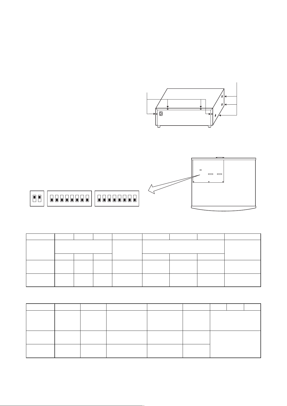
Step 1. Remove 4 screws on the amplifier rear panel and a total of 6 screws on the sides to remove the
cover.
Step 2. Set the amplifier's internal DIP switches SW2, SW3, and SW4 according to the table below.
Step 3. Replace the amplifier cover using the screws removed in Step 1.
SW2 switch setting (All switches are factory-preset to OFF position.)
SW3 switch setting (All switches are factory-preset to OFF position.)
* This function is set in relation to the SW2-8 switch. (For details, see p. 26 "GENERAL-PURPOSE
BROADCAST PRIORITY" of the instruction manual supplied with the VM-2120 or VM-2240.)
Switch No. 1 2 3 4 5 6 7 8
Function
Input 1 Input 2 Input 3 Message 3 Message 4 Message 5
ON 1 1 1 1 3 3 3
OFF 2 2 2 2 1 1 1
Priority Mode
for Same
Priority Unit
Unit No. Priority
(Numerical order)
First/Last
Priority
Inputs 1 – 3
Broadcast Priority Level
Voice Announcement Board's
Message Priority Level
TEL Paging
Priority Level
Switch No. 1 2 3 4 5 6 7 8
Function
ON Mixed Silent On Sub-unit
(off)
OFF Off
(on)
First/Last
Priority*
First-come
first-served
Last-come
first-served
Not mixed
Evacuation
message
Master
unit
Priority 2
Mixing
Mode after
Emergency Talk
Input 3/LINE
(Input 3/MIC)
Chime On/Off
Unit Type No. of Connected
Units
See the Connected
unit No. table on the
next page.
Side: M4 x 8 machine screw ..... 3 pieces each
Rear: M3 x 6 machine screw and M3 plain washer ..... 4 pieces
SW4
SW3
SW2
Internal DIP switches
SW4 SW3
ON
1
ON
2
234567
1
8
SW2
ON
2345678
1
VM amplifier's front panel
Page 11
11
Connected unit No. table (SW3)
* The total number of one Sub-VM amplifier and up to 4
Remote Microphones (excluding the Master amplifier
and Remote Microphone Extension)
SW4 switch setting (Both switches are factory-preset to ON position.)
* Determines the attenuation level when the broadcast of higher priority (level 2 or 3) overrides the BGM
broadcast (priority level 4). (For details, see p. 26 "GENERAL-PURPOSE BROADCAST PRIORITY" of the
instruction manual supplied with the VM-2120 or VM-2240.)
USE OF VR COVERS
The VM-2120/-2240 has 4 VR covers attached as accessories. They are prepared as security covers for the
setting of volume and tone controls. Remove the knob of volume or tone control and put the VR cover instead
of it.
If you need more VR covers, they are available as spare parts.
Switch No.
No. of Connected Units*
6 7 8
OFF OFF OFF 0
ON OFF OFF 1
OFF ON OFF 2
ON ON OFF 3
OFF OFF ON 4
ON OFF ON 5
Switch No.
BGM broadcast volume attenuation*
1 2
OFF
OFF
No attenuation
ON
–28 dB (just audible)
ON Don't care –∞dB (inaudible)
Page 12

Page 13

13
Nur für qualifizierte Servicetechniker
INSTALLATIONSANLEITUNG FÜR DIE
SYSTEMMANAGEMENT-VERSTÄRKER
VM-2120 UND VM-2240
Das vorliegende Handbuch enthält Anweisungen für qualifizierte Servicetechniker zur Ausführung der
im Inhaltsverzeichnis angegebenen Arbeiten.
Bitte beachten Sie auch die den Systemmanagement-Verstärkern VM-2120 und VM-2240 beiliegende
Bedienungsanleitung.
Wir weisen darauf hin, dass die Kapitelnummern und -überschriften im vorliegenden Handbuch denen
der Bedienungsanleitung entsprechen.
INHALT
13. KOMPENSATIONSSPULE ................................................................................................. 14
14. EINBAU UND ANSCHLUSS DER EINGANGSÜBERTRAGER
14.1. Einbau der Übertrager ......................................................................................................... 15
14.2. Abschalten der Phantomspeisung ....................................................................................... 16
14.3. Wichtige Anweisung für den 2-Verstärker-Betrieb
(Hauptverstärker und Erweiterungsverstärker) ................................................................... 16
15. EINBAU EINES OPTIONALEN EV-200 TEXTWIEDERGABEMODULS ............. 17
16. EINBAU EINER OPTIONALEN ÜBERWACHUNGSKARTE SV-200M ................. 19
20. ÄNDERN DER LAUTSPRECHERLINIENSPANNUNG ............................................. 21
23. EINSTELLUNGEN AN DEN FUNKTIONSSCHALTERN
23.2. Interne Funktionsschalter des VM-Verstärkers ................................................................... 22
VERWENDUNG VON VR-ABDECKUNGEN ........................................................................ 23
Page 14

14
13. KOMPENSATIONSSPULE
Achtung: Die folgenden Arbeiten dürfen nur von einem qualifizierten Fachmann ausgeführt werden.
Stellen Sie sicher, dass das Gerät spannungslos ist (Netzstecker gezogen).
Hinweis: In den Ländern der europäischen Union (EU) und solchen, die die Direktive zur
elektromagnetischen Verträglichkeit der EU in nationales Recht umgesetzt haben, muss die
Kompensationsspule eingebaut sein. Die mit dem CE-Zeichen versehenen VM-Verstärker tragen
zusätzlich die Kennzeichnung „ER“ neben der Modellbezeichnung auf der Verpackung und sind
bereits mit der Kompensationsspule ausgerüstet.
Wenn das Kästchen auf der Rückseite des Verstärkers mit einem Kreuz versehen ist, dann ist eine
Kompensationsspule installiert. In diesem Fall entfallen die folgenden Schritte. Nach Einbau einer
Kompensationsspule versehen Sie das Kästchen mit einem Kreuz.
Mit dem Einbau der optionalen Kompensationsspule CT-200M wird eine Belastung des Stromnetzes mit
Oberschwingungen der Netzfrequenz verhindert.
Schritt 1. Entfernen Sie die 4 Schrauben an der Gehäuserückseite und die 6 Schrauben an den
Gehäuseseitenwänden und nehmen die Gehäuseabdeckung ab.
Schritt 2. Bauen Sie die Kompensationsspule nahe dem Netzanschluss in das Gerät ein.
Befestigen Sie die Kompensationsspule mit ihren Zubehörschrauben an der Geräteunterseite.
Schritt 3. Ziehen Sie die Steckbrücke vom Anschluss CN1202
der Netzanschlussplatine ab.
Schritt 4. Stecken Sie die Buchse der Kompensationsspule auf
den Anschluss CN1202 der Netzanschlussplatine.
Schritt 5. Setzen Sie die Gehäuseabdeckung auf den Verstärkers und befestigen Sie sie mit den zuvor in
Schritt 1 gelösten Schrauben an der Gehäuserückseite und den Gehäuseseitenwänden.
k
Seitenwände: M4 x 8 Schrauben ... je 3 Stüc
Rückseite: M3 x 6 Schrauben und M3 Unterlegscheiben ..... 4 Stück
Rückseitige Gehäusewand CT-200M Kompensationsspule
Geräteunterseite
Schrauben 4 x 10
Netzanschlussplatine
Steckbrücke
Stecker der Kompensationsspule
3
4
Netzanschluss
Rückseitige Gehäusewand
CT-200M Kompensationsspule
Page 15

15
14. EINBAU UND ANSCHLUSS DER EINGANGSÜBERTRAGER
Achtung: Die folgenden Arbeiten dürfen nur von einem qualifizierten Fachmann ausgeführt werden.
Stellen Sie sicher, dass das Gerät spannungsfrei ist (Netzstecker gezogen).
14.1. Einbau der Übertrager
Sie können die Eingänge 1 – 3 [INPUT 1 – 3], die Sprechstellen- (RM) und Telefoneingänge [TEL] am Gerät
vom elektronisch symmetrierten Betrieb auf erdfrei symmetrisch Betrieb umrüsten. Löten Sie dazu den
optionalen Eingangsübertrager IT-450 in die dafür vorgesehene Position ein.
Schritt 1. Entfernen Sie die 4 Schrauben an der Gehäuserückseite und die 6 Schrauben an den
Gehäuseseitenwänden und nehmen die Abdeckung ab.
Schritt 2. Herausnehmen der Übertragerplatine(n)
[Eingänge 1 – 3]
Nehmen Sie die Übertragerplatine der Eingänge 1 – 3 [INPUT 1 – 3] heraus. Sie ist auf der oberen
Platine hinten links (über der Hauptplatine des Geräts) installiert.
[Sprechstellen- (RM) oder Telefoneingang (TEL)]
Nehmen Sie die RM/TEL-Übertragerplatine heraus. Sie ist auf der Platine hinten links unten
(Hauptplatine) des Geräts installiert.
k
Seitenwände: M4 x 8 Schrauben ... je 3 Stüc
Rückseite: M3 x 6 Schrauben und M3 Unterlegscheiben ..... 4 Stück
Eingangsübertrager RM/TEL-Übertragerplatine
Übertragerplatine der Eingänge 1 – 3
obere Platine
links hinten
untere (Haupt-)Platine links hinten
Page 16

16
Schritt 3. Löten Sie den Eingangsübertrager auf die herausgenommene Übertragerplatine (5 mögliche Plätze).
Hinweis: Verwechseln Sie nicht die Lötseite mit der Einbauseite.
Schritt 4. Trennen Sie die Brücken (Jumper) an den mit einem Kreuz markierten zwei Stellen je Eingang für
die umzurüstenden Eingänge auf.
Hinweis: Die Brücken befinden sich in der unten stehenden Abbildung auf der Rückseite der Platine.
[Übertragerplatine der Eingänge 1 – 3]
[RM/TEL-Übertragerplatine]
Schritt 5. Stecken Sie die Übertragerplatine(n) wieder auf die Platine(n).
Schritt 6. Setzen Sie die Gehäuseabdeckung auf den Verstärkers und befestigen Sie sie mit den zuvor in
Schritt 1 gelösten Schrauben an der Gehäuserückseite und den Gehäuseseitenwänden.
14.2. Abschalten der Phantomspeisung
Die Phantomspeisung der Eingänge 1 - 3 kann durch das Auftrennen der folgenden Drahtbrücken auf der
Übertragerplatine abgeschaltet werden (siehe Abbildung oben).
Eingang 1: SJP1301
Eingang 2: SJP1304
Eingang 3: SJP1307
14.3. Wichtige Anweisung für den 2-Verstärker-Betrieb (Hauptverstärker und
Erweiterungsverstärker)
• Stellen Sie sicher, dass Sie die Brücken SJP1401, SJP1402 und SJP1403 auf der RM/TEL-
Übertragerplatine im Erweiterungsverstärker aufgetrennt haben.
• Für den Übertragerbetrieb des Sprechstelleneingangs muss der Eingangsübertrager auf der RM/TEL-
Übertragerplatine im Hauptverstärker eingebaut sein. Trennen Sie darüber hinaus die Brücken SJP1402 und
SJP1403 auf, nicht jedoch SJP1401.
Brücken für Eingang 1 Brücken für Eingang 2 Brücken für Eingang 3
(SJP1303)
(SJP1301)
(SJP1302)
Brücken für
Sprechstelle (RM)
(SJP1305)
(SJP1306)
INPUT 1 INPUT 2 INPUT 3
(SJP1304)
(SJP1307)
Brücke für Eingang 2
Brücke für Eingang 1
Phantomspeisung
(SJP1402)
(SJP1401)
(SJP1403)
RM TEL
Phantomspeisung
Brücke für Eingang 3
Phantomspeisung
(SJP1404)
(SJP1405)
Brücke für Gleichspannungsversorgung zur Sprechstelle
(SJP1308)
(SJP1309)
Brücken für
Telefoneingang (TEL)
Page 17

17
15. EINBAU EINES OPTIONALEN EV-200 TEXTWIEDERGABEMODULS
Achtung: Die folgenden Arbeiten dürfen nur von einem qualifizierten Fachmann ausgeführt werden.
Stellen Sie sicher, dass das Gerät spannungsfrei ist (Netzstecker gezogen).
Schritt 1. Stellen Sie den DIP-Schalter auf der EV-200 Karte wie in der Abbildung gezeigt ein.
EV-200 Überwachungssignalausgang (Schalter Nr. 2)
Die EV-200 Karte sendet immer ein 1kHz-Sinussignal an einen Verstärker, wenn die EV-200 Karte keine
Audiosignale wiedergibt. Der Verstärker erkennt das 1kHz-Signal. Ist dieses Signal nicht vorhanden, nimmt
der Verstärker eine Fehlfunktion der Karte an. Daraufhin leuchtet die Fehleranzeige auf.* (Das Fehlersignal
steht am Steuerungsanschluss [CONTROL I/O] zur Verfügung.)
* Steht der Schalter Nr. 2 auf OFF, leuchtet die Fehleranzeige auch dann, wenn die Karte korrekt funktioniert.
Schritt 2. Entfernen Sie die 4 Schrauben an der Gehäuserückseite und die 6 Schrauben an den
Gehäuseseitenwänden und nehmen die Abdeckung ab.
Schritt 3. Schließen Sie das Anschlusskabel der EV-200 Karte an den Anschluss CN8 auf der Hauptplatine
im Verstärker an.
k
Einige der Komponenten können durch elektrostatische Entladungen zerstört werden. Stellen Sie daher
sicher, dass Sie bei den Arbeiten ladungsfrei sind.
DIP-Schalter
EV-200 Karte
DIP-Schalter
ON
3
4
OFF
SW 1
1
3
4
2
F
F
O
SW 1
1
2
F
F
O
Immer auf OFF setzen
(ON Position ist für Test im Werk)
EV-200 Überwachungssignal ein/aus (Schalter Nr. 2)
muss unbedingt auf ON stehen. (1 kHz Signalausgang)
Seitenwände: M4 x 8 Schraube ..... je 3 Stüc
Rückseite: M3 x 6 Schraube und M3 Unterlegscheibe ..... 4 Stück
EV-200 Anschlusskabel
CN6
CN8
Rückseitige Gehäusewand
EV-200 Karte
Stecker CF-Speicherkarte
Page 18

18
Schritt 4. Bauen Sie die EV-200 Karte in den Verstärker mittels der zwei mitgelieferten Schrauben ein.
Schritt 5. Prüfen Sie den DIP-Schalter auf der EV-200 Karte erneut auf die richtige Einstellung.
(Siehe Schritt 1)
Schritt 6. Setzen Sie die Gehäuseabdeckung auf den Verstärkers und befestigen Sie sie mit den zuvor in
Schritt 2 gelösten Schrauben an der Gehäuserückseite und den Gehäuseseitenwänden.
Schutzabdeckung der Speicherkarte [CompactFlash Karte]
Nehmen Sie vor dem Einschieben der CF-Speicherkarte die Schutzabdeckung ab, indem Sie die zwei
Schrauben lösen. Stellen Sie sicher, dass Sie die Abdeckung danach wieder anbringen.
EV-200 Anschlusskabel
CN8
M3 x 6 Schrauben ..... 2 Stück (mit der EV-200 geliefert)
EV-200 Karte
CF-Speicherkarte
M3 x 4 Schraube (2 Stück)
EV-200 Karte
Schutzabdeckung der CF-Speicherkarte
Page 19

19
16. EINBAU EINER OPTIONALEN ÜBERWACHUNGSKARTE SV-200M
Achtung: Die folgenden Arbeiten dürfen nur von einem qualifizierten Fachmann ausgeführt werden.
Stellen Sie sicher, dass das Gerät spannungsfrei ist (Netzstecker gezogen).
Schritt 1. Stellen Sie den DIP-Schalter auf der Überwachungskarte SV-200M wie in der Abbildung gezeigt ein.
Schalterstellung für das Zeitintervall der Lautsprecher-Linienüberwachung
SW1-1 SW1-2 SW2-1
Länge des Zeitintervalls
OFF OFF OFF
keine automatische
Intervallmessung
ON OFF OFF
10 Minuten
OFF ON OFF
20 Minuten
ON ON OFF
30 Minuten
OFF OFF ON
30 Minuten
ON OFF ON
40 Minuten
OFF ON ON
50 Minuten
ON ON ON
60 Minuten
In dieser Einstellung kann die Linienüberwachung
durch Aktivierung des Steuereingangs „Aktivierung
Kontrollmessung“ des Steuerungsanschlusses
[SURVEILLANCE I/O] der Überwachungskarte
aktiviert werden.
Die Lautsprecherlinien werden automatisch in
den gewählten Zeitintervallen überprüft.
SW2-2
Bedeutung der Einstellung
OFF
Deaktiviert (Kommunikation unmöglich)
ON
Aktiviert (wenn SV-200M Karte im VMVerstärker installiert ist)
Kommunikation mit VM-Verstärkern (VM-2120 oder VM-2240)
Schritt 2. Entfernen Sie die 4 Schrauben an der Gehäuserückseite und die 6 Schrauben an den
Gehäuseseitenwänden und nehmen die Abdeckung ab.
k
Einige der Komponenten können durch elektrostatische Entladungen zerstört werden. Stellen Sie daher
sicher, dass Sie bei den Arbeiten ladungsfrei sind.
SW 1 SW 2
ON
1
Zeitintervall der Lautsprecher-Linienüberwachung
ON
1
2
2
Kommunikation mit VM-Verstärkern
muss unbedingt auf ON stehen.
SW 1 SW 2
SV-200M Karte
Seitenwände: M4 x 8 Schraube ..... je 3 Stüc
Rückseite: M3 x 6 Schraube und M3 Unterlegscheibe ..... 4 Stück
Page 20

20
Schritt 3. Nehmen Sie das Abdeckblech der Öffnung des Anschlusses [SURVEILLANCE I/O] der
Überwachungskarte von der Rückwand des Verstärkers ab, indem Sie die zwei Raststifte
entfernen.
Schritt 4. Lösen Sie die 2 Sechskant-Schraubmuttern an
der 25-poligen Sub-D-Buchse auf der
Überwachungskarte SV-200M.
Schritt 5. Schließen Sie das Anschlusskabel der Überwachungskarte SV-200M an die Platinen des VM-
Verstärkers an.
5-1. Ziehen Sie die Steckbrücke vom unten abgebildeten Anschluss (CN1003) auf der Relaisplatine ab.
5-2. Schließen Sie die zwei Kabel der Überwachungskarte SV-200M an die Anschlüsse der Platinen der
VM-Verstärker wie unten gezeigt an.
Schritt 6. Bauen Sie mittels der zwei Sechskant-
Schraubmuttern die SV-200M Karte in den
Verstärker ein.
Schritt 7. Prüfen Sie die DIP-Schalter auf der
Überwachungskarte SV-200M erneut auf die
richtige Einstellung. (Siehe Schritt 1)
Schritt 8. Setzen Sie die Gehäuseabdeckung auf den Verstärkers und befestigen Sie sie mit den zuvor in
Schritt 2 gelösten Schrauben an der Gehäuserückseite und den Gehäuseseitenwänden.
Abdeckblech der Öffnung des Anschlusses [SURVEILLANCE I/O]
der Überwachungskarte
Raststift
Überwachungskarte SV-200M
Sub-D-Buchse
Sechskant-Schraubmutter
CN6 Anschlusskabel
5
-2
CN1003 Anschlusskabel
Relaisplatine
Überwachungskarte
SV-200M
Sub-D-Buchse
CN1003
Steckbrücke
5
-1
CN6
CN8
Gehäuserückwand
Überwachungskarte SV-200M
Sechskant-Schraubmutter
Page 21

21
20. ÄNDERN DER LAUTSPRECHERLINIENSPANNUNG
Achtung: Die folgenden Arbeiten dürfen nur von einem qualifizierten Fachmann ausgeführt werden.
Stellen Sie sicher, dass das Gerät spannungsfrei ist (Netzstecker gezogen).
Die Lautsprecherlinien sind werkseitig auf 100 V eingestellt. Für 70 V oder 50 V Linienspannung ändern Sie
die interne Verdrahtung wie unten gezeigt.
Schritt 1. Entfernen Sie die 4 Schrauben an der Gehäuserückseite und die 6 Schrauben an den
Gehäuseseitenwänden und nehmen die Abdeckung ab.
Schritt 2. Ziehen Sie den 9-poligen Stecker vom Anschluss CN1102
auf der Platine mit dem Zonenlautstärkestellern
(Zonenschalter) heraus.
Schritt 3. Zum Einstellen der gewünschten Linienspannung
tauschen Sie die Drähte im Kabelstecker gemäß den
Farbkodierungen in der Tabelle unten aus.
Schritt 4. Schließen Sie den Kabelstecker wieder an die Platine an.
Schritt 5. Setzen Sie die Gehäuseabdeckung auf den Verstärkers
und befestigen Sie sie mit den zuvor in Schritt 1 gelösten
Schrauben an der Gehäuserückseite und den
Gehäuseseitenwänden.
Belegung des Steckers CN1102
Lautsprecherlinienspannung/-impedanz
Kabel vom Stecker trennen
Das Kabel lässt sich herausziehen, indem man mit einem spitzen Gegenstand, z. B. einer Pinzette, wie unten
gezeigt auf die Verriegelung drückt.
Lautsprecher CN1102 Pinnummer
linienspannu ng
123456789
100 V Weiß Violett Blau Grün Gelb Orange Rot Braun Schwarz
70 V Violett Blau Grün Gelb Orange Rot Braun Weiß Schwarz
50 V Blau Grün Gelb Orange Rot Braun Weiß Violett Schwarz
Lautsprecherlinienspannung VM-2120 VM-2240
100 V 83 Ohm 42 Ohm
70 V 42 Ohm 21 Ohm
50 V 21 Ohm 10 Ohm
Anschluss CN1102
Vorderseite des VM-Verstärkers
Kabel herausziehen
Auf die Verriegelung drücken
1
9
Page 22

22
23. EINSTELLUNGEN AN DEN FUNKTIONSSCHALTERN
23.2. Interne Funktionsschalter des VM-Verstärkers
Achtung: Die folgenden Arbeiten dürfen nur von einem qualifizierten Fachmann ausgeführt werden.
Stellen Sie sicher, dass das Gerät spannungsfrei ist (Netzstecker gezogen).
Schritt 1. Entfernen Sie die 4 Schrauben an der Gehäuserückseite und die 6 Schrauben an den
Gehäuseseitenwänden und nehmen die Abdeckung ab.
Schritt 2. Stellen Sie die internen DIP-Schalter SW2, SW3 und SW4 des Verstärkers entsprechend der
Tabellen unten ein.
Schritt 3. Setzen Sie die Gehäuseabdeckung auf den Verstärkers und befestigen Sie sie mit den zuvor in
Schritt 1 gelösten Schrauben an der Gehäuserückseite und den Gehäuseseitenwänden.
Einstellung der DIP-Schalterreihe SW2 (Alle Schalter sind werkseitig auf OFF gestellt)
k
Schalter
Nr.
Funktion
ON
OFF
1
Eingang
1
1
2
2
Eingang
2
1
2
3
Eingang
3
1
2
4
Prioritätsstufe
Telefoneingang
1
2
Prioritätsstufen der
Eingänge 1 – 3
5
Nachricht
3
3
1
6
Nachricht
4
3
1
7
Nachricht
5
3
1
8
Prioritätsreihenfolge
bei gleicher
Prioritätsstufe
Priorität nach
Geräte-Nr.
(numerisch)
gegenseitig
verriegelnd /
ablösend
Prioritätsstufen der Nachrichten
des Textspeichermoduls
Seitenwände: M4 x 8 Schrauben ... je 3 Stüc
Rückseite: M3 x 6 Schrauben und M3 Unterlegscheiben ..... 4 Stück
SW4
SW3
Interne DIP-Schalter
SW4 SW3
ON
1
ON
2
234567
1
SW2
ON
8
2345678
1
Vorderseite des VM-Verstärkers
SW2
Page 23

Einstellung des Schalters SW3 (Alle Schalter sind werkseitig auf OFF gestellt)
* Diese Funktion wird abhängig von den Schaltern SW2-8 eingestellt (Für nähere Informationen siehe S. 26
„11 Prioritäten im Normalbetrieb“ in der Bedienungsanleitung, die den Verstärkern VM-2120 und VM-2240
beiliegt).
Tabelle Anzahl angeschlossener Geräte (SW3)
* Gesamtanzahl aus der Summe Erweiterungsverstärker und bis zu 4 Sprechstellen (Hauptverstärker und
Tastaturerweiterung werden nicht mitgezählt)
Einstellung des Schalters SW4 (beide Schalter sind werkseitig auf ON gestellt)
* Bestimmt die Lautstärkeabsenkung, wenn eine Übertragung höherer Priorität (Priorität 2 oder 3) die
Wiedergabe der Hintergrundmusik (Priorität 4) überschneidet. (Für nähere Informationen siehe S. 26 „11
Prioritäten im Normalbetrieb“ in der Bedienungsanleitung, die den Verstärkern VM-2120 und VM-2240
beiliegt).
VERWENDUNG VON VR-ABDECKUNGEN
Der VM-2120/-2240 hat als Zubehör 4 Abdeckungen für die Lautstärkesteller. Sie sind zum Schutz der
Einstellungen der Lautstärke und des Klangs vorgesehen. Nehmen Sie den Knopf für die Lautstärkebzw.
Klangeinstellung ab und setzen Sie die VR-Abdeckung an deren Stelle ein.
Wenn Sie weitere VR-Abdeckungen benötigen, sind diese als Ersatzteile verfügbar.
23
Schalter Nr. Anzahl angeschlossener
6 7 8
Einheiten *
OFF OFF OFF 0
ON OFF OFF 1
OFF ON OFF 2
ON ON OFF 3
OFF OFF ON 4
ON OFF ON 5
Schalter Nr. Lautstärkeabsenkung der
1 2 Hintergrundmusik*
OFF
OFF keine
ON –28 dB (leise hörbar)
ON egal –∞dB (unhörbar)
Schalter
Nr.
Funktion
ON
OFF
1
gegenseitig
verriegelnd /
ablösend *
gegenseitig
verriegelnd
gegenseitig
ablösend
2
Priorität 2
mischend
Mischbetrieb
nicht
mischend
3
Modus nach
Notfalldurchsage
Stille
Evakuierungsdurchsage
5
Gerätetyp
Erweiterungs
verstärker
Hauptverstärker
4
Eingang 3 / Hochp.
(Eingang 3 / Mikr.)
Gong ein/aus
ein
(aus)
aus
(ein)
Anzahl angeschlossener
Einheiten
Siehe Tabelle
'Anzahl angeschlossener
Einheiten auf
der nächsten
Seite
6
78
Page 24

Page 25

25
Pour Technicien qualifie uniquement
NOTICE D'INSTALLATION POUR SYSTEME
VM-2120 et VM-2240
Cette notice donne aux techniciens qualifies les instructions a suivre pour la programmation et
l'equipement voir les indications ci-jointes.
Utiliser cette notice en complement du manuel d'instruction fournis avec l'appareil.
Nota: La numerotation et le nom des paragraphes sont les memes que sur le manuel d'instruction du
VM-2120 et VM-2240.
TABLE DES MATIERES
13. INSTALLATION TRANSFORMATEUR D'ISOLEMENT ............................................. 26
14.
INSTALLATION TRANSFORMATEUR D'ENTREE ET MODIFICATION CARTE
14.1. Installation du transformateur .............................................................................................. 27
14.2. Mise hors tension de l'alimentation fantôme ........................................................................ 28
14.3. Instructions lorsque les amplificateurs maître et esclave sont raccordés ............................ 28
15. MONTAGE DE LA CARTE D'ANNONCE VOCALE EV-200 (EN OPTION) ......... 29
16. MONTAGE DE LA CARTE DE SURVEILLANCE SV-200M (EN OPTION) .......... 31
20. CHANGEMENT DE LA TENSION DE LA LIGNE HAUTS-PARLEURS ............... 33
23. FONCTIONNEMENT DU COMMUTATEUR DE FONCTION
23.2. Les commutateurs de fonction internes de l'amplificateur VM ............................................ 34
Utilisation des capots de protection des boutons
(decrit uniquement dans ce manuel
) ................................................................................... 35
Page 26

26
13. INSTALLATION TRANSFORMATEUR D'ISOLEMENT
Attention: Cette opération doit être effectuée par un technicien de maintenance qualifié.
S'assurer que l'alimentation AC est bien coupée avant chaque opération.
Si une case est cochée "X" avec l'indication "Le Transfo est installé" sur le panneau arrière de l'amplificateur,
cela signifie que la bobine d'arrêt a été installée. Les opérations suivantes ne sont donc pas nécessaires.
Lorsque vous installez la bobine d'arrêt, n'omettez pas de cocher la case d'une croix "X".
Pour éliminer les radiations harmoniques des composants de la ligne d'alimentation de l'appareil, installer la
bobine CT-200M.
Nota: dans les pays où l'usage de la marque de conformité CE est obligatoire, la bobine d'arrêt doit être
installée.
Etape 1. Retirer les 4 vis du panneau arrière de l'amplificateur et les 6 vis sur les côtés pour retirer le capot.
Etape 2. Installer le transfo à proximité de la prise d'alimentation à l'intérieur de l'appareil.
Fixer la bobine avec les vis prévues à cet effet de l'intérieur bas de l'appareil.
Etape 3. Retirer le cavalier du connecteur de la
carte d'alimentation (CN1202).
Etape 4. Insérrer le connecteur de la bobine
dans le connecteur de la carte
d'alimentation (CN1202).
Etape 5. Remonter le capot de l'amplificateur en utilisant les 4 vis du panneau arrière et les 6 vis des
panneaux latéraux retirées lors de l'étape 1.
Côté: vis M4 x 8 ..... 3 par côté
Arrière: 4 vis M3 x 6 et rondelles M3
Panneau arrière
Côté bas
Bobine CT-200M
Vis à tôle 4 x 10
Connecteur cavalier
3
Carte d'alimentation
4
Connecteur bobine
Prise secteur
Panneau arrière
Bobine CT-200M
Page 27

27
14. INSTALLATION TRANSFORMATEUR D'ENTREE ET MODIFICATION CARTE
Attention: Cette opération doit être effectuée par un technicien de maintenance qualifié.
S'assurer que l'alimentation AC est bien coupée avant chaque opération.
14.1. Installation du transformateur
Vous pouvez convertir la section d'entrée audio au niveau des bornes d'entrée 1 – 3, de la borne du Pupitre
Microphone (RM), de la borne Appel Telephone (TEL) de l'appareil pour les faire passer de type symétrie
élec-tronique au type symétrie par transformateur. Souder le transformateur IT-450 (option) à la section
d'entrée requise.
Etape 1. Retirer les 4 vis du panneau arrière de l'amplificateur et les 6 vis sur les côtés pour retirer le capot.
Etape 2. Démonter la carte du transformateur d'entrée
[Entrées 1 – 3]
Retirer la carte de transformateur d'entrée 1 – 3 installée en partie supérieure de la carte circuit de
l'appareil.
[Pupitre Microphone (RM) ou Appel Telephone (TEL)]
Retirer la carte de transformateur d'entrée RM/TEL installée en partie supérieure de la carte circuit
de l'appareil.
Côté: vis M4 x 8 ..... 3 par côté
Arrière: 4 vis M3 x 6 et rondelles M3
Transformateur d'entrée
Transformateur d'entrée entrées 1 – 3
Transformateur d'entrée RM/TEL
Carte circuit
supérieure
Carte circuit inférieure
Page 28

28
Etape 3. Souder le transformateur d'entrée à la carte de transformateur qui a été démontée (5
emplacements).
Nota: Attention à souder le bon côté pour le montage.
Etape 4. Couper les fils des cavaliers (2 emplacements repérés par X pour chaque entrée).
Nota: Les cavaliers sont de l'autre côté de la carte circuit comme indiqué ci-dessous.
[Transformateur d'entrée entrées 1 – 3]
[Carte de transformateur d'entrée RM/TEL]
Etape 5. Replacer la carte de transformateur d'entrée sur la carte circuit.
Etape6. Remonter le capot de l'amplificateur en utilisant les 4 vis du panneau arrière et les 6 vis des
panneaux latéraux retirées lors de l'étape 1.
14.2. Mise hors tension de l'alimentation fantôme
En coupant les fils des cavaliers sur la carte de transformateur d'entrées 1 – 3, on peut couper l'alimentation
fantôme de l'entrée correspondante (voir illustration ci-dessus.)
Entrée 1: SJP1301
Entrée 2: SJP1304
Entrée 3: SJP1307
14.3. Instructions lorsque les amplificateurs maître et esclave sont raccordés
• Veiller à couper les fils des cavaliers SJP1401, SJP1402, et SJP1403 de la carte de transformateur RM/TEL
de l'amplificateur esclave VM.
• Pour que le Pupitre Microphone (RM) soit isolé par transformateur, veiller à installer le transformateur
d'entrée sur la carte de transformateur d'entrée RM/TEL de l'amplificateur maître VM. Couper aussi les fils
des cavaliers SJP1402 et SJP1403 en prenant soin de laisser le cavalier SJP1401 intact.
Cavaliers pour entrée 1
(SJP1303)
Cavaliers pour entrée 2
INPUT 1 INPUT 2 INPUT 3
(SJP1301)
(SJP1302)
Cavalier pour entrée 1
alimentation fantôme
(SJP1402)
Cavaliers pour RM
(SJP1401)
(SJP1403)
(SJP1305)
(SJP1306)
(SJP1304)
Cavalier pour entrée 2
alimentation fantôme
RM TEL
Cavaliers pour entrée 3
(SJP1308)
(SJP1307)
(SJP1309)
Cavalier pour entrée 3
alimentation fantôme
(SJP1404)
Cavaliers pour TEL
(SJP1405)
Cavalier pour alimentation DC vers RM
Page 29

29
15 MONTAGE DE LA CARTE D'ANNONCE VOCALE EV-200 (EN OPTION)
Attention: Cette opération doit être effectuée par un technicien de maintenance qualifié.
S'assurer que l'alimentation AC est bien coupée avant chaque opération.
Etape 1. Régler le commutateur DIP de la carte EV-200 comme ci-dessous.
Sortie signal de surveillance EV-200 (Commutateur N° 2)
La carte EV-200 transmet systématiquement un signal sinusoïdal de 1 kHz à un amplificateur si la carte EV200 ne reproduit pas des signaux audio. L'amplificateur détecte l'existence d'un signal de 1 kHz. Lorsque le
signal n'existe pas, l'amplificateur en impute le défaut à la carte et déclenche l'allumage de l'indicateur de
défaut FAULT.* (Le signal indiquant le défaut de la carte EV-200 est transmis à partir du connecteur de
commande CONTROL I/O.)
* Si le commutateur N° 2 est sur la position OFF, l'indicateur de défaut s'allume même si la carte fonctionne
correctement.
Etape 2. Retirer les 4 vis du panneau arrière de l'amplificateur et les 6 vis sur les côtés pour retirer le capot.
Etape 3. Insérer le câble de raccordement EV-200 venant de la carte EV-200 dans le connecteur CN8 de
l'amplificateur.
Ne pas manipuler l'appareil, si vous etes charges en electricite statique,car certains composants y sont
tres sensibles.
Commutateur DIP
Carte EV-200
Commutateur DIP
ON
3
4
OFF
SW 1
1
3
4
2
F
F
O
SW 1
1
2
F
F
O
Toujours sur OFF.
(ON est la position pour les tests usine.)
Marche-arrêt sortie du signal de surveillance EV-200 (Switch N° 2)
Vérifier qu'il est sur ON. (sortie signal A 1 kHz)
Côté: vis M4 x 8 ..... 3 par côté
Arrière: 4 vis M3 x 6 et rondelles M3
Câble de raccordement EV-200
CN6
CN8
Panneau arrière
Carte EV-200
Connecteur carte CF
Page 30

Etape 4. Monter la carte EV-200 dans l'amplificateur à l'aide des vis fournies avec la carte EV-200.
Etape 5. Vérifier à nouveau le réglage du commutateur DIP de la carte EV-200 (voir Etape 1.)
Etape 6. Remonter le capot de l'amplificateur en utilisant les 4 vis du panneau arrière et les 6 vis des
panneaux latéraux retirées lors de l'étape 2.
Capot de protection de la carte CF
Retirer 2 vis pour détacher le capot de protection et insérer la carte CF dans le slot. Ne pas oublier de
remettre le capot après avoir inséré la carte.
30
Câble de raccordement EV-200
CN8
2 vis M3 x 6 (fournies avec la carte EV-200)
Carte EV-200
Carte CF
2 vis M3 x 6
Carte EV-200
Capot de protection de la carte CF
Page 31

31
16. MONTAGE DE LA CARTE DE SURVEILLANCE SV-200M (EN OPTION)
Attention: Cette opération doit être effectuée par un technicien de maintenance qualifié.
S'assurer que l'alimentation AC est bien coupée avant chaque opération.
Etape 1. Régler le commutateur DIP de la carte SV-200M comme ci-dessous.
Temps d'activation de la surveillance de la ligne hauts-parleurs
Ce réglage exécute la détection de défauts grâce au
signal d' "activation de surveillance de la ligne hautsparleurs" venant de l'entrée de commande externe
(connecteur sub-D 25 broches SURVEILLANCE I/O).
Les lignes hauts-parleurs sont contrôlées systématiquement à intervalles réguliers programmés.
Communications avec l'amplificateur VM (VM-2120 ou VM-2240)
Etape 2. Retirer les 4 vis du panneau arrière de l'amplificateur et les 6 vis sur les côtés pour retirer le capot.
Ne pas manipuler l'appareil, si vous etes charges en electricite statique, car certains composants y sont
tres sensibles.
SW1-1 SW1-2 SW2-1 Réglages
OFF OFF OFF activation automatique
désactivée
ON OFF OFF intervalles 10 minutes
OFF ON OFF intervalles 20 minutes
ON ON OFF intervalles 30 minutes
OFF OFF ON intervalles 30 minutes
ON OFF ON intervalles 40 minutes
OFF ON ON intervalles 50 minutes
ON ON ON intervalles 60 minutes
SW2-2 Réglages
OFF Désactivé (communications impossibles)
ON Activé lorsque la carte SV-200M est
installée dans l'amplificateur VM)
SW 1 SW 2
ON
1
Temps d'activation de la surveillance de la ligne hauts-parleurs
ON
1
2
2
Communication avec les amplificateurs VM
Veiller à le mettre sur ON.
SW 1 SW 2
Carte SV-200M
Côté: vis M4 x 8 ..... 3 par côté
Arrière: 4 vis M3 x 6 et rondelles M3
Page 32

32
Etape 3. Démonter le cache de surveillance I/O du panneau
arrière de l'amplificateur en enlevant les 2 rivets.
Etape 4. Dévisser les 2 vis hexagonales situées sur le
connecteur sub-D 25 broches de la carte SV-200M.
Etape 5. Raccorder la carte SV-200M aux cartes de l'amplificateur VM à l'aide des câbles de raccordement.
5-1. Retirer le cavalier du connecteur de carte relais (CN1003) comme ci-dessous.
5-2. Raccorder les 2 câbles joints à la carte SV-200M aux connecteurs des cartes de l'amplificateur VM
comme indiqué ci-dessous.
Etape 6. Monter la carte SV-200M dans l'amplificateur à l''aide
des 2 vis.
Etape 7. Vérifier à nouveau que le commutateur DIP de la carte
SV-200M est sur la bonne position (voir Etape 1.)
Etape 8. Remonter le capot de l'amplificateur en utilisant les 4 vis du panneau arrière et les 6 vis des
panneaux latéraux retirées lors de l'Etape 2.
Cache de Surveillance I/O
Rivet
Câble de raccordement CN6
5
-2
Câble de raccordement CN1003
CN1003
Connecteur sub-D
Vis hexagonales
CN6
CN8
Carte SV-200M
Carte SV-200M
Connecteur sub-D
Carte relais
5
Cavalier
-1
Panneau arrière
Carte SV-200M
Vis hexagonales
Page 33

33
20. CHANGEMENT DE LA TENSION DE LA LIGNE HAUTS-PARLEURS
Attention: Cette opération doit être effectuée par un technicien de maintenance qualifié.
S'assurer que l'alimentation AC est bien coupée avant chaque opération.
La tension de la ligne hauts-parleurs de l'amplificateur VM est prévue pour une sortie de 100 V. Pour 50 V ou
70 V, modifier le câblage interne du connecteur comme ci-dessous.
Etape 1. Retirer les 4 vis du panneau arrière de l'amplificateur et les 6 vis sur les côtés pour retirer le capot.
Etape 2. Retirer le connecteur (9 broches) raccordé au connecteur
CN1102 de la carte circuit avec la commande de volume
de zone (commutateur de sélection).
Etape 3. Remplacer les fils insérés dans le connecteur du câble par
des fils selon le codage couleur indiqué dans le tableau cidessous pour mettre sur la tension de ligne désirée.
Etape 4. Raccorder le connecteur câble à la carte circuit.
Etape 5. Remonter le capot de l'amplificateur en utilisant les 4 vis
du panneau arrière et les 6 vis des panneaux arrières
retirées à l'étape 1.
Allocation des broches du connecteur
Tension/impédance ligne HP
Comment retirer les câbles du connecteur
Tirer sur le câble en appuyant sur le ressort d'arrêt avec un objet pointu comme ci-dessous.
Tension ligne HP Numéro de broche du connecteur CN1102
123456789
100 V Blanc Violet Bleu Vert Jaune Orange Rouge Brun Noir
70 V Violet Bleu Vert Jaune Orange Rouge Brun Blanc Noir
50 V Bleu Vert Jaune Orange Rouge Brun Blanc Violet Noir
Tension ligne HP VM2120 VM-2240
100 V 83 Ω 42 Ω
70 V 42 Ω 21 Ω
50 V 21 Ω 10 Ω
Connecteur CN1102
Panneau avant de l'amplificateur VM
Tirer sur le câble
1
Appuyer sur les ressorts d'arrêt
9
Page 34

34
23. FONCTIONNEMENT DU COMMUTATEUR DE FONCTION
23.2. Les commutateurs de fonction internes de l'amplificateur VM
Attention: Cette opération doit être effectuée par un technicien de maintenance qualifié.
S'assurer que l'alimentation AC est bien coupée avant chaque opération.
Etape 1. Retirer les 4 vis du panneau arrière de l'amplificateur et les 6 vis sur les côtés pour retirer le capot.
Etape 2. Régler les commutateurs DIP (SW2, SW3, et SW4) selon le tableau ci-dessous.
Etape 3. Remonter le capot de l'amplificateur avec les vis retirées lors de l'étape 1.
Réglage du commutateur SW2 (tous les commutateurs sont réglés en usine sur OFF)
Réglage du commutateur SW3 (tous les commutateurs sont réglés en usine sur OFF)
* Cette fonction est réglée en relation avec le commutateur SW2-8 (voir p. 26 "PRIORITE DE DIFFUSION
GENERALE" pour plus de détails.)
Commutat. 1 2 3 4 5 6 7 8
Fonction
Entrées 1 – 3
Niveau priorité de diffusion
TEL Paging
Niveau priorit.
Niveau de priorité des messages
de la carte d'annonce vocale
Mode priorité
pour un même
appareil priorité
Entrée 1 Entrée 2 Entrée 3 Message 3 Message 4 Message 5
ON
111 1 3 3 3
Priorité appareil
(ordre numérique)
OFF
222 2 1 1 1
Priorité
Premier/dernier
Commutat. 1 2 3 4 5 6 7 8
Priorité
1er/dernier*
Priorité 2
Mixage
Mode après
annonce d'urgence
Entrée 3/LINE
(Entrée 3/MIC)
Carillon On/Off
Type appar.
Nombre d'appareils
raccordés
Fonction
First-come
1er servi
Mixé Muet
On
(off)
Esclave
Voir tableau des
Nos. des appareils
next page.
ON
Last-come
1er servi
Not mixed
Evacuation
message
Off
(on)
MasterOFF
Côté: vis M4 x 8 ..... 3 par côté
Arrière: 4 vis M3 x 6 et rondelles M3
SW4
SW3
Commutateurs DIP internes
SW4 SW3
ON
1
ON
2
234567
1
SW2
ON
8
2345678
1
VM amplifier's front panel
SW2
Page 35

Tableau des numéros d'appareils raccordés (SW3)
Réglage du commutateur SW4 (les deux commutateurs sont réglés en usine sur ON)
*Détermine le niveau d'atténuation lorsqu'une diffusion de plus haute priorité (niveau 2 ou 3) passe par
dessus la diffusion BGM (niveau de priorité 4). (Voir p.26 "PRIORITE DE DIFFUSION GENERALE")
Utilisation des capots de protection des boutons
Les appareils VM-2120 et VM-2240 sont livres avec 4 capots de protection pour bouton. Ces capots servent a
proteger les reglages de volume ou de tonalite. Enlever les boutons de volume ou de tonalite et mette a la
place les capots fournis.
Des capots de protection complementaires peuvent etres fournis en piece detachee.
N° des appareils raccordés*
0
1
2
3
4
5
35
Commutateur N°
678
OFF OFF OFF
ON OFF OFF
OFF ON OFF
ON ON OFF
OFF OFF ON
ON OFF ON
Atténuation volume de diffusion BGM*
Pas d'atténuation
–28 dB (juste audible)
– ∞ dB (inaudible)
Commutateur N°
12
OFF
OFF
ON
ON Sans importance
* Nombre total de un amplifcateur esclave VM
et jusqu'à 4 Pupitres Microphones (à
l'exclusion de l'amplificateur Maître et de
l'extension de Pupitre Microphone)
Page 36

133-12-764-70
 Loading...